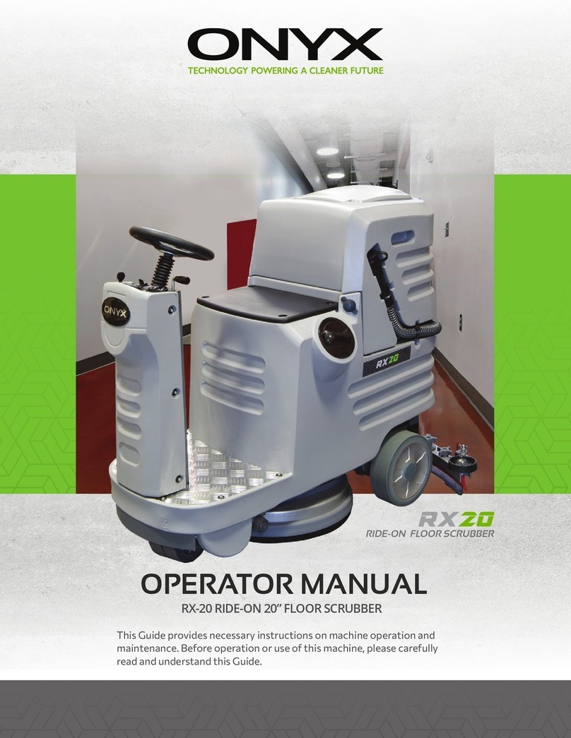
Onyx RX-34 User manual

RIDE-ON FLOOR SCRUBBER
This Guide provides necessary instructions on machine operation and
maintenance. Before operation or use of this machine, please carefully
read and understand this Guide.
OPERATOR MANUAL
RX-34 RIDE-ON 34” DUAL HEAD / BATTERY SCRUBBER

Website: https://www.onyxsolutions.com
Machine Information:
Model number: _____________________________________________________________________
Machine serial number: ____________________________________________________________
Sales representative: _______________________________________________________________
PO number: _________________________________________________________________________
Date PO placed: _____________________________________________________________________
Installation Date: ____________________________________________________________________
12703 Commerce Station Dr • Suite 200
Huntersville, NC 28078
704.827.9368
TABLE OF CONTENTS
Parts Ordering
Warranty Claims
Technical Support
Protect the Environment
Safety Precautions
General Information
Technical Perameters
Control System
Common Safety Guide
Machine Unpacking
Unloading Packing
Treatment After Unloaded Packing
Use of Scrubber-Dryer
Start the Scrubber-Dryer
Rules of Operation
Process of Cleaning
Chosing the right Detergent
Machine Maintenance
Brush Replacement
Ready to Use the Machine
Transmission
Suction Head’s Rubber Blade
Driving Operation
Braking System
Suction Motor
Battery
Battery Charger Connection
Troubleshooting
Wiring Diagram
4
4
4
4
5
6-9
7
9-12
13
13
13
13
14
14
14
15
16
17
17
18
18
19
20
21
22
23-25
24
25-27
27
RIDE-ON FLOOR SCRUBBER

4 5
PARTS ORDERING
When ordering the replacement parts, please refer to the ONYX website at www.onyxsolutions.com. Use
of the published Illustrated Parts Lists (IPL’s) to identify the correct part number required is required to
support accuracy of parts ordering.
Machine IPL’s can be found at the top of the SHOP page of the ONYX website. Before matching parts
accessories from any authorized service center or dealer by telephone at 704-827-9368, or email us at
sales@onyxsolutions.com.
WARRANTY CLAIMS
ONYX Warranty Statement (policy) and Warranty Claim form can be found on the SUPPORT page of the
ONYX website, www.onyxsolutions.com/warranty-submission
TECHNICAL SUPPORT
Technical support is available by submitting a HELP TICKET on the CONTACT US page of the ONYX website,
www.onyxsolutions.com/productsupport.
PROTECT THE ENVIRONMENT
Please abandon the old machine components such as packaging material, battery,
etc. and toxic liquid such as anti-freezing agent and oil according to your local regu-
lations on waste disposal and on the premise of maintaining environmental safety.
Please ensure to carry out the recycling well.
12703 Commerce Station Dr • Suite 200
Huntersville, NC 28078
704.827.9368
SAFETY PRECAUTIONS
The following notation is to arouse the reader / user note, to enable the machine used correct and safe.
Preliminary information
The following notation is to arouse the reader / user note, to enable the machine used
WARNING: Special emphasis on the process to avoid damage to the machine and any
generation of hazardous conditions.
DANGER: Stressed that this action will cause great danger, the operator must be
especially careful to avoid personal injury.
IMPORTANT!
Be sure to read this manual carefully Need readily available. If it is damaged or missing, contact your
dealer or contact the manufacturer asking for a copy. We reserve our right to modify products, but also
haven’t got obligation to update the old manual. Before open and use automatic scrubber-dryer, please
fully in accordance with the table in the contents. We are very pleased that our machines you can choose,
if problems please feel free to tell us, we will be your requirements to do the most satisfactory answer.
WARNING:
1) This machine is designed to be used only for automatic washing and drying Machine. Therefore, we
The risk borne by the user. Special needs to be emphasized is that this machine can not be used tractors
and manned use.
2) The automatic washing machine to dry the carpet outside the level of inter(Or) 10%
of the slope angle) caused by any question Problems, sabotage, accidents without
changes without permission.
4) The automatic scrubber-dryer used materials must be authorized.
5) When the machine still works, keep a safe distance.
6) When use of the machine, keep other people, especially children in a safe distance.
-
ing items:
9) Transportation of this scrubber-dryer must be safe.
10) The batteries must be checked inside the room with ventilation Environment.
11) The dirt collected in the machine must be disposed in a proper placed under the law.

6 7
GENERAL INFORMATION
ACCESSORIES
When you need replace parts, only use original accessories by manufacturers. To avoid more serious
damage to the machine and make the machine perform better, please replace spare parts on time.
TECHNICAL PERAMETERS
Performance
Maximum cleaning area
Cleaning width
Suction head width washing
Maximum transmission speed
Maximum reverse speed
Maximum operating speed
Maximum working gradient
Unit
m2/h
mm
mm
km/h
km/h
km/h
%
RX-34
5800
860
1100
5
4
5
15
Noise Levels (ISO 3744/95)
Noise when working
Unit
db(A)
RX-34
< 70
Brush
Brush
Brush location
Brush speed
Brush downward pressure
Brush lifting system
Brush diameter
Unit
rpin
Kg
type
mm
RX-34
2/disc(A)
main
210
30
electric
410
Vibration
Frequency of vibration acceleration values
Unit
m/s
RX-34
< 0.5
Squeegee
Squeegee
Lift up and down
Unit
type
type
RX-34
electrical
Water Tank
Clean water tank capacity
Sewage tank capacity
Trash box
Vacuum Operation
Unit
it
it
it
mm/H2O
RX-34
150
165
1600
Operation
Steering wheel
Front wheel with the pinion and gear drives
Minimum U-turn space
Unit
type
mm
RX-34
mechanical
1380
Driving Motor
Constitution
Type
Power
Brush Driving Motor
Constitution
Type
Power
Vacuum Motor
Constitution
Type
Power
Total Power
Unit
type
Unit
type
Unit
type
W
RX-34
Metal
MR250
1-36-800
RX-34
CIMA
RX-34
EDTGTRS V36H38
1-36-600
2400
GENERAL INFORMATION

8 9
Battery
Battery quantity & capacity
Battery size (L x W x H)
Water in the battery
Continuous working time
Unit
mm
type
h
RX-34
1-36-320
760X10X460
Distilled Water
4*
GENERAL INFORMATION GENERAL INFORMATION
DRIVING
Forward and backward.
TYPE
Front wheel drive
Wheel
Front wheel
Back Wheel
Unit
mm
mm
RX-34
250
300
Brake
Brake Pedal
Parking Brake
Unit
type
type
RX-34
Mechanical
Mechanical
Machine Size
Length
Width
Height
Unit
mm
mm
mm
RX-34
1640
830
1400
Weight
Mechanical weight (not including battery)
Mechanical weight (including battery)
Weight before working
Battery Weight
Unit
kg
kg
kg
kg
RX-34
310
721
837
411
Apparatus
Water tank warning light
Low water tank warning light
Battery warning light
Battery warning light and alarm display
Emergency stop switch
Speed switch
Brush Pressure gauge pressure
Forward / Reverse switch
Vacuum motor switch
Brush Switch
Speaker
RX-34
X
X
X
X
X
X
X
X
X
Standard Accessories
Absorbing strip
Brush
RX-34
X
Options
A. Round Brush
B. Rolling Brush
RX-34
X
X

10 11
CONTROL SYSTEM
1. Brake Pedal / Parking Brake Lever
2. Throttle Step Board
3. Water Tank Cock Hand Lever Switch
4. Vacuum Motor / Absorb Head Control Switch
5. Emergency Stop Switch
6. Speakers
7. Speed Switch
8. Power Alarm and Display Alarm
9. Dirty Water Tank Full Warning Lights
10. Clean Water Tank Empty Warning Light
11. Brush Control Switch
12. Start Switch
13. Forward / Reverse Joystick
14. Tank Cover
15. Reverse Alarm
1
2
3
14
4
5
6
7
8 10
9
13
12
11
15
CONTROL SYSTEM
1. The brake pedal / parking brake hands lever.
Pedal 1 is the control of the machine’s pedal travel or work Brake
lever 2 lock pedal 1 and control the machine parking and Brake. (See the
“brake” section)
2. The accelerator pedal
Control the front / back speed.
3. Tank petcock switch hand lever
Open positions 1-4.
4. Vacuum motor and suction switch
Control vacuum motor and lower the suction head.
Location. “Fan” vacuum motor on, water suction head down.
5. The emergency stop knob
When an emergency occurs, press the switch. Restart operation, turn the
knob counter clockwise 1 / 4.
7. Speed Switch
Used to set the speed when moving or working.
speed in order to thoroughly clean.
Transferred to the “High” setting the machine to identify the
high-speed, clean faster.
9. Dirty water tank full warning light
sends alarm signal when dirty water tank is full.
8. Power alarm and display alarm
Displays the machine’s working time and status of battery, sends alarm signal when battery is low.
6. Speakers
Control horn operation.
1
2
3
4
56
7
8 9

12 13
CONTROL SYSTEM COMMON SAFETY GUIDE
14
10
13
12
11
15
10. Clean water tank empty warning light
11. Brush control switch
Control the rotation of the brush motor and brush upgrade down.
Location, rush “: motor on, brush down.
12. Key start switch
Activate all of the electrical control system components. Loca-
Location. “1” electrical system open
13. Forward and reverse selection lever
Provide washing machine forward and backward.
Position “Forward”: washing machine go forward.
Position “Backward: Washing machine go back.
14. Water tank cap
15. Back and forward warning light (red)
This light indicates the wrong reverse activated and stop the
machine. Continue, as 13 operation described.
WARNING: The machine can only be used by authorized operators. Prevent unauthorized
of the machine are prohibited. It will not cause danger if you check the machine when the
the machine is prohibited. Please wear gloves and sun-protected glasses while working
outdoors.
DANGER: In addition to the rules need to be addressed, the person in charge of the machine
must make the following clear to the machine operators: Fixed or mobile hoses must be
placed on the correct position. If the rack is removed, or the security system is not con-
nected or short circuit, regardless of any reason, the machine must be repaired immediately
before the operation. The machine can only be used under the proper conditions according
to proper purpose of use. Comply with the same request in accordance with the purpose
of the use and maintenance instructions, and in accordance with professional inspection
toxic liquids and dust. It is dangerous to touch the moving parts of the machine, this kind
a hood, please do not operate in an toxic smoke area and hazardous area. Prohibit persons
other than the operators to transport.
In this manual, the machine described in line with EC standards and on the machine with a number
98/37/EEC (machinery standards). Person in charge of the machine must comply with EEC directives
and local regulation of the working environment to ensure the operation of machinery healthy and safe.
Usually start the machine before a preliminary examination.
Forklifts must be placed so that the center of the machine has a half in the truck on the. Packaging must
be very careful to avoid collision. need to raise the machine or lift too high.
Opening the machine must be careful and gentle. Machines must use metal or wooden ramp into the
ground.
After unpacking, check the machine, install the battery if it isn’t installed , if there is a short distance
transport after use, disconnect battery cable, remove the brush and suction cutter head. Before the
long-distance transport, the machine should be restored to the original packaging. The machine can be
implemented within a short distance.
MACHINE PACKING
UNLOADING PACKING
TREATMENT AFTER UNLOADED PACKING

14 15
USE OF SCRUBBER-DRYER PROCESS OF CLEANING
WARNING:
WARNING: This type of operation must implemented in the place where unauthorized
order to complete the cleaning process, perform the following procedure: press the but-
ton labeled with brush mark 11( Figure .3) to start the brush motor. Turn on clean water
clean water control lever 3 in the middle, so that the entire surface behind the brush will be
immediately wet, and there will be no excess water spilling out of the squeegee. Press the
button to start the vacuum motor, to lower the squeegee. Step on the accelerator pedal
2(Figure 3), the machine will move forward in the required speed and cleaning job begins.
You can choose the speed of the machine by turn the “high low speed switch” to left to run
speed to get better cleaning results. There are two speeds to choose from. Rotary switch
thoroughly clean. Transferred to the “High” setting the machine to identify the high-speed,
clean faster.
Necessary prevention
1, The machine must be used only by competent and reliable personnel.
2, when the machine is not in use, unplug the start key , and put hand brakes on
3, when the machine is not in use, lift up the brush in order to avoid distortion of brush 4, Do not park on
the slope.
The process of using the scrubber machine is very simple. Experience can help you choose the most suit-
able cleaning brush and cleaning detergent, to make decision when to use cleaning and drying processes
-
um sewage.
When moving the machine backward, pull the joystick 14 (Figure 3) backwards, when vacuuming and
cleaning operations are completed, perform the following process.
Don’t allow other people close to the machine. Machines can only be used by an experienced operator au-
thorized by the person in charge. The operator must be in proper physical and mental state, not in alcohol,
Ensure the following:
There is no unrelated things on the machine. (Eg, tools, rags, equipment, etc..)
After turning on the machine, there is not a strange noise. If there is a strange noise, you must immediately
Do not lower or raise any doubt about the safety of the operation. Must not work in any way reduce the
stability of the machine.
use the machine in a dark environment. Required special attention near the shelf.
2. Fill up the clean water tank 1.
3. Check the brush raised to above ground. (button 11 for a “stop” Figure .3) *
4. Check the brake is released
5. Insert the key 5 to the total control panel (Fig.3) and clockwise (this will give total control system
power supply).
6. Press the button 4 to turn on the suction motor (Fig.3).
7. Press the button 11 to turn on the brush motor (Fig.3).
8. Open solution tank by the pressing handle to lever 3. (Fig.3).
9. Move the joystick 14 on the location of A. (Figure .3)
10. Begin to travel and get a good speed, slow step on the power pedal 2 (Fig.3).
START THE SCRUBBER-DRYER
RULES OF OPERATION
WARNING: Do not use water suction system when the water used out. If this happens, it is
treated as the improper use of the machine, and the loss of the machine warranty.
to the clean water tank. The clean water tank is made of polyethylene material, with anti-acid, and an-
ti-solvent to most detergents. After wash, rotate the control lever 3, with the hose 2, the sewage water
will be discharged from the sewage tank. Clean the sewage tank thoroughly at least once a week, open
operations.
WATER FILL AND DRAINAGE (TFIGURE 4)

16 17
CHOOSING THE RIGHT DETERGENT MACHINE MAINTENANCE
Select detergent
To obtain good cleaning results, make sure to use the appropriate detergent. If necessary, ask the supplier
for professional advice, and remember over using strong detergent may shorten the working life of the
machine.
Be sure to use low foam detergent or anti-foaming agent, which can avoid damage to the water motor. If
you can not get these products, you can use this alternative method, the use of 50cc ordinary wine vinegar
before adding recycling bins. Use it clear water tank.
Must clean the sewage tank every eight hours, in accordance with the following program:
- Twist the handle 5, opened the lid 6.
- Using the sponge, or high-pressure water gun clean the sewage water tank
- After the completion of the above one by one close the lid 6 immediately
DANGER: Do not use corrosive products damage water tanks and your health. Necessary to
use gloves and protective glasses.
1
4
1
6 5
3
2
WARNING: Before replacing brush, pull start key on the panel to ensure that the motor will
not accidentally start.
BRUSH REPLACEMENT
spring 2, as shown in the arrow
Then brush 2-3-4-5 set to leave the center of1.
Spin out from the screw 3, remove the brush 5 from the bracket 4.
Install a new brush, please follow the following procedure: with screws 3, the mounting bracket 4 new
Adjustment of suction head
In order to meet packaging needs, suction head is individually packaged, it should be installed on the drive
plate, the step is as follows:
1. Raise the pallet
2. Insert the screws 1 to number 2 and keep a slight tilt as shown in the photo.
3. Lift suction rake head to the left hand side so that the 3 can insert to 4.
4. load the.R split-pin 4 will be released within at pin 3.
5. Install the suction tube in the mouth of suction head.
-
ant. A rubber brush behind at the strips must be slightly tilted. Shown: this solution will gather in front of
the body. To achieve this process the following order: Loosen the nut 6 and 7 clockwise to tighten, Increase
or counterclockwise to reduce the angle of perspective.
When established the right angle, re-tighten the nut 6.
AB
READY TO USE THE MACHINE

18 19
1
2
3
4
8
5
7
6
READY TO USE THE MACHINE SUCTION HEAD’S RUBBER BLADE
Suction head above the ground water height must be adjusted to the appropriate height of plywood and
rubber band size too. This operation complished by adjusting the nut 8 meters as follows:
Adjusting nut 8 clockwise to increase height between suction and the ground
and reduce the pressure on the ground.
Adjusting nut counterclockwise to lower height between suction and the ground and increase the pres-
To make a rubber band long life, the pressure is as little as possible to achieve better drying results.
Check the case of vacuum cleaner motors
Check all the water tank’s entrance is closed.
and replacement work to prevent the destruction of ground loss.
Replace blade
Attention
replaced.
Blade replacement process is as follows: to raise the tray out of the machine head and suction tube 1. Low-
er suction head, release screw, pull out the R split-pin A and put it in pin B. Loosen the 8 knobs back of belt
3 of and 4 screws back of belt 5.Rotate rubber blade in order to use the new blade. Rubber blade has two
new one. In contrast with the above procedures that a new blade can be installed. The installation process
Scrubber-dryer is driven by the electrical
system, electric power system consists of
a front wheel and two electronic controled
driven wheel.
forward or backward.
of the machine
Instrument panel has switch 14 of three
the pace. Travel or work (please refer to
control introduction of -10-point)
Warning!
In the driver version S/2-RS/2 and ‘`ZAPI”
the third gear speed electric system can be
used only for turning not for work.
In the driver version T and “ELEK D ROS-
ISTEM “ the third gear speed can be used
for turning around and work .
TRANSMISSION
1
B
A
23
4
56 7
2
2

20 21
DRIVING OPERATION SYSTEM BRAKING SYSTEM
The main driving force generated by wheel 2 spread to wheel 3, and through the driving wheel 3 Imple-
menting the front-wheel drive. While driving, the driver control the resistance felt by the steering wheel
size,the resistance can be adjusted through the regulation of the nut 4 .
1
23
4
Brake system allows washing cars stop in the movement and remain stationary, but also make the vehicle
stable in the inclined plane.
1, The brake system works through the step on the foot brake 1 (see Figure 1) brake back wheels making
brakes achieved.
2,Braking is achieved through the manipulation of mechanical devices (see Figure 11).
3,The parking brake system can be locked, follow these steps:
(A) step the foot brake pedal 1 (see Figure 3) in the end.
(B) push the joystick 2 (see Figure 3) to the parking stalls.
The step to unlock brake system was: push lever 2 after slam their feet on the foot brake (see Figure 3) to
the appropriate gear. After that they can take the foot brake on the driving control. 4, In case of controlling
the vehicle, foot brake does not work, you can adjust it through the regulator 3 to achieve correction.
WARNING: At least every three months to check and adjust the brakes once.
1
2
3

22 23
SUCTION MOTOR BATTERY
Button 4 (Figure 3) is water motor’s control switch.
-
in Figure 13). Installation follow reverse above steps.
WARNING: The water motor’s liner must be checked every six months once, in case of
damage please change a new one. Liner replacement following these steps: Remove the
plastic cup 5, release the nut, remove the liner base, carefully check the liner. Installation
follow reverse above steps.
1
2
3
4
5
BATTERY
Check thet battery performance
The density of the electrolyte is closely related to the battery performance, therefore, measuring the elec-
trolyte density is crucial. Battery electrolyte in the normal state of charge density should be at about 1.260
(300B e). If the density is between 1.26 (300B e) and 1.2 to 240B e), and electrical storage pool only par-
tially charged. If the density is less than 1.14 (180B e), it means that the electrical storage pond has expired.
Measuring electrolyte density
The density of the electrolyte is closely related to the battery performance, therefore, the measurement
must be very careful. Electrolyte density measured by density meter. Please note that the correct place
density meter in the measure process . In the determination, such as needing to add distilled water, electro-
lyte, it must read the data after both mixing fully .
battery initial use, water must be added after each charge. Use for some time, Number may be reduced
with water views, according to the actual situation , but must ensure that not less than 1 times per week.
Charge limit
The battery after being used for some time, if the density is not lower than the value measured 1.24( 280B
-
tery life. Solutions liquid’s suitable temperature when Charging should be less than 450C or less. When
charging if the electrolyte is higher than environment temperature 10-120C, No matter how much the tem-
perature of the electrolyte, over-charging of circumstances may occur. When the meter shows that only
Battery charging areas
Battery in the charging process will produce a certain fuel gas, where the charging process of charging ar-
maintain adequate Ventilation but also to ensure that the room temperature maintained at 40-45C below.
Place in the charge of existing inadequate ventilation circumstances, the user can set up ventilation ducts
(Can’t share a emission Mouth with the original chimney), or install a fan to resolve the problem.
Not continuous use or long-term idle
If the battery is not used continuously, even if the electrolysis liquid number is in the normal range, every
month, users must give the battery discharge to keep cells alive again
If the battery needs a long period idle, it must be saved in a dry cool place.
Users must recharge the battery completely at least a time monthly. At the thorough process of charging,
the battery’s every single cell should be seen bubbling, voltage and electrolyte density reading number
must have a stable record of 3-4 hours.
Under any circumstances, battery of a long idle time must be charged before use and electrolysis quality
testing.
Install the battery
The steps to install the battery components are as follows:
Remove the steering wheel, unscrew the nut 1 (see Figure 13)
Move away Block, unscrew the nut 2 (see Figure 13)
Remove the battery strap, unscrew the nut 3 (see Figure book 13)
Before installing the battery, be sure to check all the components necessary to be intact. Battery has clean
appearance. In connection access port of Vaseline or grease can be coated. if the battery electricity has
been loss before installation, then wait until after full installation.

24 25
BATTERY CHARGER CONNECTION BATTERY
Steps to replace batteries is as follows:
1. Remove the steering wheel
2. Remove Seat
3. Remove the strap
(1) sweeper must be checked its security, damage or failure by professional and technical personnel in ac-
-
tenance In a certain time interval, implement in accordance with the “routine maintenance and operational
control” instruction sheet.
2) every 6 months in normal working status check safety devices,
inspector must be the authority of the expert organization.To ensure the Safety devices in normal opera-
tion,the machine must be checked 5 years each school year by skilled personnel histology.
) The person responsible for the machine must be checked annually in accordance with the conditions
required by the machine, check the machine during the period, the responsible person must judge whether
sweeping machines are still in accordance with technical safety regulations. Then mark the drawing board
to come up with what has been said checked.
1
2
3
SECURITY CHECK ROUTINE CONTROL
OF MAINTENANCE OPERATIONS
Perform regular maintenance procedures
Clean repair water tank
Check the vacuum pipe and suction head
Check the brush status
Check the edge of the suction head
Gear chain oiling
Check the motor brushes every six months
Check safety devices (micro-switch, horn, emergency stop button, etc.)
Each Interval
840 125 200 500 1500
X
X
X
X
X
X
X
X
X
X
Suction head inadequate
drying
Old rubber adhesive
Tube is free from obstruction
Adjustment of brush is not suitable
Suction head blocked
Burning vacuum cleaner motor
Motor carbon brush old
Brush position is not low enough
Replace Rubber
Clean Pipes
Adjust brush
Clean block at suction head
Check and replace the motor
Replacing carbon brushes
Check the lower brush
Problem Reason Solution
TROUBLESHOOTING
on the brush average
Brush water supply blocking
Cleaning agent valve closed or not open enough
Water pipes by extrusion
No water in water tank
Washing pipe lines
Open the cleaning agent valve
Restoration or replace of piping
Add water to the tank

26 27
TROUBLESHOOTING TROUBLE SHOOTING
After the machine is not
moving the work forward
Stop the machine
has water leakage
Vacuum cleaner motor
shut down or start
machine
Drive pedal failure
Control component failures
Liquid valve open
Damage to piping or seals
Brake is pressed
Check the connection
Check the control section
Release brake switch
Close the valve
Replacement of pipes or seals
Problem Reason Solution
Machine wash result is not
satisfatory
Old brush Replace brush
Increase the brush pressure
Problem Reason Solution
Machine can not start
The machine does not
start or stop suddenly
The main switch between 5 and 3 can not switch
Battery unit burn
Micro switch set incorrectly
Pressed with a sudden emergency stop button
Clockwise rotation switch
Connect the battery
then restart
empty the water tank
Release button and start the process
repeatedly
Replace Micro Switch
Release emergency stop and restart
the machine(See washing machine
start program)
Dashboard errors led to the brush on ground pressure is
not enough
micro switch under the seat of power has error or not
connected
(Drive S and Jumbo series, this will be displayed through
the instrument panel 72 the alarm code)
The operator has started and the seat of micro fuse has
been broken
When the red light on, check, if nec-
essary, replace. Warning! Fuse is in the
control unit, never use a high-level
fuse, as it will cause harm. If the fuse
repeatedly has error, please contact
service center.
Battery terminal relaxation
Replace or connect Micro-switch
The system can not
reduce the increase in
brush
Fuse fault
Starter can’t accept the current
Starter motor damage
Circuit board problem
Replacement
Check
Replacement
Replace circuit board
Problem Reason Solution
www.onyxsolutions.com/productsupport
1
1
2
2
3
3
4
4
D D
C C
B B
A A
M
+
- +
-
+
MM
Key Switch
BK
BK
RD
RD
BK
M
BKBK
RD
5A Thermal
Circuit Breaker
Vac
Motor
Brush
Motor
Traction
Motor
Battery/Hour
Meter
Charging Port
Controller
FUSE
150A
Emergency Button
M
Brush Lift
Motor
Vac Lift
Motor
Clean Water Light
Hazard Light
Horn
Sewage Water Light
M
TankEmpty liquid level switch
Brush+Vac Switch
Brush Switch
Vac Switch
Foot Pedal/Throttle
BK
BL+BK
PR
Backward
Forward
TankFull liquid level switch
Solenoid
Water Valve
Solenoid Brake
Color Codes:
BK = Black WT= White
RD = Red BN = Brown
YL = Yellow GY= Gray
GN = Green BL = Blue
PR = Purple PK = Pink
OG = Orange CY = Cyan
Note: Colors may Vary
BK
OG
RD
YL
BK
BK+RD
GN+WT
YL+GN
BK
BK
BK
RD
RD
RD
RD
RD
BK
RDRD
OG
YL
BL
BK+RD
Water
Pump
PK+BL
OG
RD
P2-8
P2-3
P2-4
B+
B-
P2-7
WH
P2-9
P2-10BN
P2-12
P2-14
P3-3
P3-6
P3-4
WH
P3-8
P3-10
PK
P3-11
P3-12
BL
YL
P3-13
GN
P3-16
P3-17
GY
P3-18
RD
PR
P3-9
P3-14
YL+GN
BK+RD
P3-19
BK+RD
P3-20
OG
P2-1 PR
P2-2 PR
BN
P2-11WH
P5-1
P5-2
BN BN
RD
PR
Horn Button
RD
BK
Status Code
BK+YL
BK+RD
OG
BK+RD
High/Low Speed Switch
+
-
-
PK+BL
PK+BL
PK+BL
BK
PK+BL
Buzzer
OG

onyxsolutions.com
Table of contents
Other Onyx Scrubber manuals