AX3700
6 Duty / 1 Standby Auto Amplifier Changeover Panel
Features technical specifications
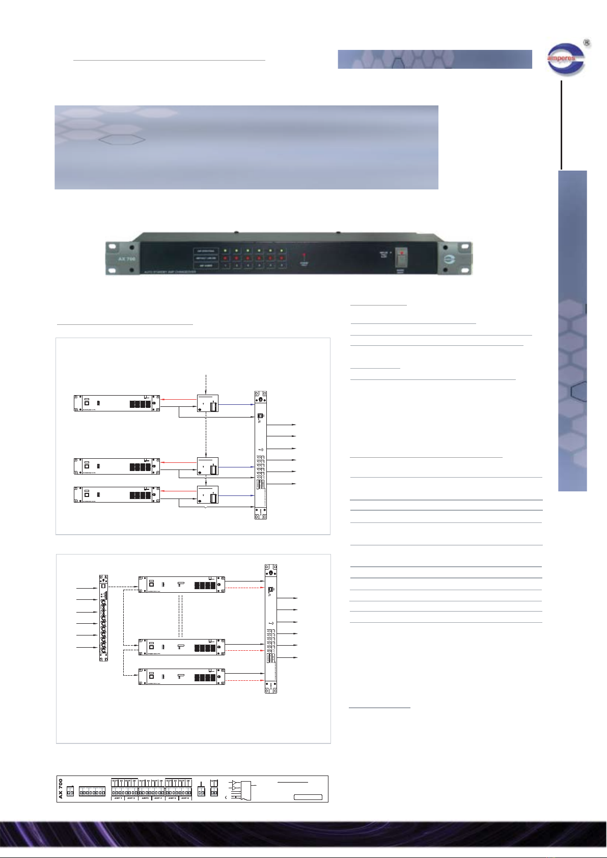
application schematic
auto amplifier changeover
Amperes AX3700 offers a great flexibility and simplicity in cabling for auto amplifier fault changeover system with its combination of amplifier
fault sensor modules and changeover panel in a box. The internally generated Pilot Tone and sensory circuit shall detect any faulty duty
amplifier and would initiate a changeover process.
AX3700 has been optimised for faster fault detection and changeover as compared with AS4000 modules. Pilot tones are generated at
intervals to avoid constant loading of power amplifiers.
Changeover are performed at both input and output sections, making it suitable for application in a matrix system. At any one time, only a
failed duty unit shall be replaced by a standby amp, to avoid overloading.
Cater for 6 duty and 1 standby
Expandable for 1 standby to cater for more than 6 duty amps.
Built in Pilot Tone generator, transmit at intervals and senses at
sequence to protect amplifiers
Overloading protection by allowing only a single take over
Prioritised changeover which higher numbered amplifier shall be
preferred for take over if more than two units are down
Shorter fault detection time from 10 to 25 seconds
Changeover at input and output section simultaneously ; suitable
for matrix system installations
Input link switch ; making connection of sources easier
Channel isolation switch for unused or un-monitored channel
Individual channel status indicators ; normal, fault and changeover
Operating voltage
Power consumption
Input signal
Input impedance
Audio output gain
Pilot tone interval
Pilot tone frequency
Detection line
Detection level
Failure detection time
Failure recovery time
Zone load rating
Status indications
Changeover alert
Changeover section
Dimensions (WxHxD)
Weight
24V DC 1 A via PS9400 PSU
7.2 W
6 ch. balanced line signal
10 K Ohm
Unity
10 secs / channel
20 KHz ( +/- 5% )
70 / 100 V line
50 V rms
10 ~ 25 seconds
20 seconds max
400W / 100V line
Normal ; Fault ; Changeover
Buzzer with switch
Input and Output simultaneously
482 x 88 x 150 mm
3.4 kg
5121
ZS
OVERRIDE
21 3 54
SPEAKERZONESELECT
6 7 8 9 10 1211
CALL
ALL
amperes
O
I
PA 2120
amperes
SIGNAL-40dB
SIGNAL-10dB
POWER
PROTECT
CLIP
2120
PA
120Watts
POWER
O
I
PA 2120
amperes
SIGNAL-40dB
SIGNAL-10dB
POWER
PROTECT
CLIP
2120
PA
120Watts
POWER
O
I
PA 2120
amperes
SIGNAL-40dB
SIGNAL-10dB
POWER
PROTECT
CLIP
2120
PA
120Watts
POWER
amperes
AX 3700
5 64321 BUZZER
AMP/LINE
ALERT
FAULT
CHANGEOVER
AMP.NUMBER
FAULT
NORMAL
S/BY
POWER
ON/OFF
PILOTTONEACTIVE
TEST MIC
SIRENACTIVATE
POWER
FIRE
amperes
AM 6000
O
I
2122
MX
amperes
SIGIN
AUX
MAXMIN MAXMIN MAXMIN MAX
SIGIN SIGIN
CH2CH1 CH3
MINMIN MAXMIN MAX
SIGINSIGIN SIGIN
CH4 CH6CH5
TONECTRL
MIN MAX
TREBLEMIXERCHIME
SIGIN
MIN
SOURCE
MIN MAXMAX
EXTINPUT
MIN MAX
BASS
SIGIN
MUSICSOURCE
MASTER
OFF
CASS
CD
TUNER
SELECTOFF
POWER
INPUT SOURCES
E/M
PANEL
DUTY AMP
DUTY AMP
STANDBY
AMP
ZONE
SELECTOR
SPEAKERS
VOL
CTRL
AX3700
24V DC
overriding
100V
100V
audio +
PT
100V
audio
24V DC
overriding
1
6s/by
1
6
100V
Cascade AX3700 is more than 6 duty
amps are installed
rear view
IN-
IN+
OUT+
IN-
IN+
OUT+
OUT-
OUT-
IN+
IN-
CHANNEL 1CHANNEL 2CHANNEL 3CHANNEL 4
CHANNEL 5CHANNEL 6 STANDBY
AMP
CHAN. 1
ON
CHAN. 2
ON
CHAN. 3
ON CHAN. 4
ON
CHAN. 5
ON
CHAN. 6
ON
HIGH
CASCADE
LOW
CHANNEL 6
DC 24V
0.5 A
+-
IN-
IN+
OUT+
IN-
IN+
OUT+
OUT-
OUT-
IN-
IN+
OUT+
IN -
IN +
OUT +
OUT -
OUT-
+ - G + -
INPUT
OUTPUT
CHANNEL 5
+ - G + -
OUTPUT INPUT
CHANNEL 4
+ - G + -
OUTPUT INPUT
CHANNEL 3
+ - G + -
OUTPUT INPUT
CHANNEL 2
+ - G + -
OUTPUT INPUT
CHANNEL 1 STANDBY
+ - G + - + - G
OUTPUT
INPUT
OUTPUT
OPENLINK
LINK
SIGNAL
OPENLINK
LINK
SIGNAL
OPENLINK
LINK
SIGNAL
OPENLINK
LINK
SIGNAL
OPENLINK
LINK
SIGNAL
AX3700
PLEASE OBSERVE POLARITY
OUT +/- --> TO ZONE SELECTOR / SPEAKERS
AMP CONNECTIONS
IN +/- --> FR. AMP OUTPUTS
MAX LOAD / CH - 400W / 100V LINE
AMP. AUTO
FAULT
CHANGE OVER
AMPLIFIER 70/100V LINE INPUTS/OUTPUTS CHANNEL / AMP. DETECTION SWITCHES
SWITCH TO OFF FOR UNUSED CHANNEL
FAULT
CONT.
3A NO
MAX
AUDIO SIGNAL INPUTS / OUTPUTS
RS 485
INPUT SIGNAL
DO NOT SWITCH TO LINK WHEN DIFFERENT AUDIO
SOURCES ARE USED FOR THE ADJACENT CHANNEL
CASCADE
CONNECT ONLY ONE WIRE FOR CASCADE TO NEXT
UNIT
UNIT 1(LOW) --- UNIT 2(HIGH)
AB
Carton : 555 (W) x 165 (H) x 295 (D) mm
Weight : 4.2 kg
Qty : 1 units / carton
packing information
amplifier changeover & monitoring
www.ampereselectronics.com Page 18
2009 : all rights reserved by amperes electronics sdn bhd the emerging preference