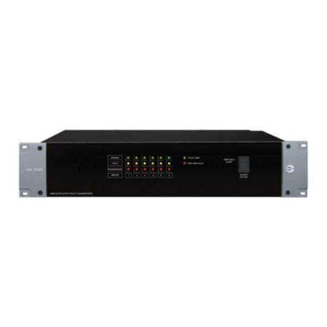
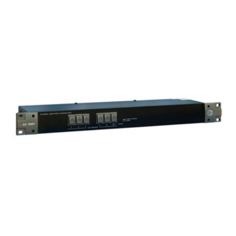
Amperes AC3801 User manual

AC 3801 amperes
1 2 345678
STANDBY AMPLIFIER CHANGEOVER
MODE
MANUAL
CHANGEOVER
PRIORITY
POWER
STANDBY FAULT
STANDBY AMPLIFIER CHANGEOVER
EXTERNAL
Thank you for choosing another quality product from Amperes Electronics.
INSTRUCTION MANUAL
AC3801
Standby Amplifier Changeover unit
AC3801 is an innovative product, integrating previous models ofAX700 andAC3601 in a box. Thereby it can be used as a
manual standby amplifier changeover or as semi auto unit which shall be used with amplifiers with auto fault sensors. In the
latter mode, the unit can be changed to manual mode, simply by changing the front mode switch.
AC3801 comes with 8 inputs for duty amplifiers with single standby power pack. Cascade is possible to enable each
standby amplifier to cater for more than 8 duty units with simple link cable.
With our continuous product improvement policy, we are simply building more efficient and reliable tool for ever increasing
demanding needs of today's PA installations. Installing AC3801 to your system, it's definitely a plus tool of performance
and reliability at a fraction of cost as compared to similar equipment in its class.

Parts Identifications
PAGE 2 AC3801 | STANDBY AMPLIFIER CHANGEOVER UNIT
AC 3801
S/BY AMP. CHANGEOVER
+
-
DC 24V
500mA
AMP. FAULT DETECT TRIGGER OUT
100V
IN
100V
COM
100V
100V
COM
COM
IN OUT
COM
AMP 1
OUT
100V
IN
100V
COM
100V
100V
COM
COM
IN OUT
COM
OUT
100V
IN
100V
COM
100V
100V
COM
COM
IN OUT
COM
OUT
100V
IN
100V
COM
100V
100V
COM
COM
IN OUT
COM
AMP 2 AMP 3 AMP 4 AMP 5 AMP 6 AMP 7 AMP 8 STANDBY
AMP
IN
100V
COM
LINK
IN
OUT
CASCADE
1 2 3 4 5 6 7 8 S/B C
DUTY AMPLIFIER INPUTS
PLEASE OBSERVE POLARITY
TO ZONE SELECTOR
AC3801
S/BY IN
WIRING CONNECTIONS
AMP.IN
AMP.OUT
OUT
IN
CASCADE LINK
DUTY AMP
S/BY AMP OR SPEAKERS
Quality Product From
AMPERES ELECTRONICS
AC 3801 amperes
1 2 345678
STANDBY AMPLIFIER CHANGEOVER
MODE
MANUAL
CHANGEOVER
PRIORITY
POWER
STANDBY FAULT
STANDBY AMPLIFIER CHANGEOVER
EXTERNAL
12
Front View
Rear View
3
4 5 6 7 8
1. LED INDICATORS
2. CHANGEOVER MODE BUTTON
LED Indicator for power and standby fault.
4. DC SUPPLY INPUT
3. CONTROL BUTTON
5. AMP. FAULT DETECT TRIGGER
6. DUTY AMPLIFIER INPUT / OUTPUT TERMINALS
Each switch represents a duty amplifier ( amp 1 to amp 8 ) respectively. Selecting any switch would lit up the LED
indicating that particular duty amplifier has been switched and the standby unit has taken over its role as duty unit.
If more than one switches is pressed, the amplifier with lower number of assignment would have priority over the higher
one, thus preventing overloading of the standby pack. It is recommended that only one switch is pressed at any one
time. ( Priority 1 : highest )
It is recommended that DC 24V supply with regulated output is connected to the unit. ie.Amperes PS9400 24V regulated
DC power supply pack.
Outputs of amplifiers 1 to 8 is connected here and subsequently to other equipments such as speaker zone selector.
Please refer to "Connecting The Unit" for proper instruction.
7. STANDBY AMPLIFIER INPUT TERMINALS
8. CASCADE LINK TERMINALS
Use this port to connect to the outputs of the standby amplifier. Please ensure correct polarity in termination.
If 2 or more AC3801 are to be installed, link each of the units via this terminal. Kindly follow the arrow as indicated for
linkage.
Amplifiers with fault sensors. eg QP2000 series has fault contacts, which shall be connected to this port.
Mode button to select manual operation or remote trigger changeover.

Schematic - Manual Amplifier Fault Changeover
AC3801 | STANDBY AMPLIFIER CHANGEOVER UNIT PAGE 3
STANDBY AMPLIFIER
DUTY AMPLIFIER # 08
DUTY AMPLIFIER # 01
AMPERES AC3801
HIGH PRIORITY
LOW PRIORITY
1 8 STANDBY AMPLIFIER INPUT
AMP OUT 1
AMP OUT 8
1
8
PUBLIC ADDRESS POWER AMPLIFIER
SIGNAL -40 dB
SIGNAL -10 dB
POWER
PROTECT
CLIP
PA 2480
amperes
PUBLIC ADDRESS POWER AMPLIFIER
SIGNAL -40 dB
SIGNAL -10 dB
POWER
PROTECT
CLIP
PA 2480
amperes
AC 3801 amperes
1 2 3 4
5
6 7 8
STANDBY AMPLIFIER CHANGEOVER
MODE
MANUAL
CHANGEOVER
PRIORITY
POWER
STANDBY FAULT
STANDBY AMPLIFIER CHANGEOVER
EXTERNAL
PUBLIC ADDRESS POWER AMPLIFIER
SIGNAL -40 dB
SIGNAL -10 dB
POWER
PROTECT
CLIP
PA 2480
amperes
The duty amplifier #01 connected to input 1 ofAC3801 shall have highest priority for standby takeover.

PAGE 4 AC3801 | STANDBY AMPLIFIER CHANGEOVER UNIT
Connecting The Unit: Manual Mode
AC 3801
S/BY AMP. CHANGEOVER
+
-
DC 24V
500mA
AMP.FAULT DETECT TRIGGER OUT
100V
IN
100V
COM
100V
100V
COM
COM
IN OUT
COM
AMP 1
OUT
100V
IN
100V
COM
100V
100V
COM
COM
IN OUT
COM
OUT
100V
IN
100V
COM
100V
100V
COM
COM
IN OUT
COM
OUT
100V
IN
100V
COM
100V
100V
COM
COM
IN OUT
COM
AMP 2 AMP 3 AMP 4 AMP 5 AMP 6 AMP 7 AMP 8 STANDBY
AMP
IN
100V
COM
LINK
IN
OUT
CASCADE
1 2 3 4 5 6 7 8 S/B C
DUTY AMPLIFIER INPUTS
PLEASE OBSERVE POLARITY
TO ZONE SELECTOR
AC3801
S/BY IN
WIRING CONNECTIONS
AMP.IN
AMP.OUT
OUT
IN
CASCADE LINK
DUTY AMP
S/BY AMP OR SPEAKERS
Quality Product From
AMPERES ELECTRONICS
AC3801
Duty 1 Power Amplifier #01
Duty 1 Power Amplifier #08
Standby Power Amplifier
100V 100V
No Connection Output 1 to 8
100V
The below diagram is suitable for amplifier without auto fault detection circuit and only requires manual changeover during
fault.
OUT
100V
IN
100V
COM
100V
100V
COM
COM
IN OUT
COM
AMP 7 AMP 8
100V COM
From amplifier
100V COM
To Speaker

PAGE 5 AC3801 | STANDBY AMPLIFIER CHANGEOVER UNIT
Connecting The Unit: Manual Mode
AC 3801
S/BY AMP. CHANGEOVER
+
-
DC 24V
500mA
AMP.FAULT DETECT TRIGGER OUT
100V
IN
100V
COM
100V
100V
COM
COM
IN OUT
COM
AMP 1
OUT
100V
IN
100V
COM
100V
100V
COM
COM
IN OUT
COM
OUT
100V
IN
100V
COM
100V
100V
COM
COM
IN OUT
COM
OUT
100V
IN
100V
COM
100V
100V
COM
COM
IN OUT
COM
AMP 2 AMP 3 AMP 4 AMP 5 AMP 6 AMP 7 AMP 8 STANDBY
AMP
IN
100V
COM
LINK
IN
OUT
CASCADE
1 2 3 4 5 6 7 8 S/B C
DUTY AMPLIFIER INPUTS
PLEASE OBSERVE POLARITY
TO ZONE SELECTOR
AC3801
S/BY IN
WIRING CONNECTIONS
AMP.IN
AMP.OUT
OUT
IN
CASCADE LINK
DUTY AMP
S/BY AMP OR SPEAKERS
Quality Product From
AMPERES ELECTRONICS
AC3801
Duty 1 Power Amplifier #01
Duty 1 Power Amplifier #08
Standby Power Amplifier
100V 100V
No Connection Output 1 to 8
100V
The below diagram is suitable for amplifier without auto fault detection circuit and only requires manual changeover during
fault.
OUT
100V
IN
100V
COM
100V
100V
COM
COM
IN OUT
COM
AMP 7 AMP 8
100V COM
From amplifier
100V COM
To Speaker

PAGE 6 AC3801 | STANDBY AMPLIFIER CHANGEOVER UNIT
Multiple Unit Installation ( Cascade)
100V
COM
IN
OUT
S/BY AMP
INPUTS CASCADE
LINK
INPUTS
S/BY AMP
COM
100V
LINK
CASCADE
OUT
IN
MULTIPLE UNIT INSTALLATION
100V
COM
IN
OUT
S/BY AMP
INPUTS CASCADE
LINK
UNIT 1
UNIT 2
UNIT 3
STANDBY AMPLIFIER
PRIORITY 2
PRIORITY 1
PUBLIC ADDRESS POWER AMPLIFIER
SIGNAL -40 dB
SIGNAL -10 dB
POWER
PROTECT
CLIP
PA 2480
amperes
PRIORITY 3
Standby amplifier input section
Whenever a standby amplifier is required to serve more than 8 duty units, cascade the AC3801 with the configuration as
shown.The numberofcascade isunlimited, butforaneffectivesystem,wewouldrecommend thatmaximum cascadeshould
be 3.
ThehighestprioritywouldbethefirstunitofAC3801at channelinput1.Thereby thisduty amplifierwould havehigher chance
of changeover in the queue.

AC3801 | STANDBY AMPLIFIER CHANGEOVER UNIT PAGE 7
Operating The Unit
Operating voltage
Power consumption
Zone load rating
No of amplifier inputs
Changeover indication
Switching mode
Cable connections
Cable size
Dimension (WxHxD)
Weight
Colour
24V DC ; 0.2A
Standby: 82mW, 3.4 mA
Operating: 1.3W, 50 mA
500W / 100V line input (max)
8 duty, 1 standby
Front panel LED for duty amplifier being Changeover
Via front panel switches (manual mode)
Remote trigger (auto mode)
Plug in detachable connectors with screw
Up to 2.5 mm sq
482 x 44 x 180 mm
2 kg
Black, powder epoxy coated
Note:
The above specifications are correct at time of printing but subjected to changes without prior notice due to product
improvements.
Cascade capacity Unlimited (Recommended 3)
Technical Specifications
1 2 345678
MODE
MANUAL
CHANGEOVER
PRIORITY
POWER
STANDBY FAULT
STANDBY AMPLIFIER CHANGEOVER
EXTERNAL
Manual Mode:
1) Press the mode button with ‘MANUAL’LED lits.
2) Determine which amplifier is faulty and press the assigned channel for standby takeover.
External Mode:
Use this mode only if amplifiers with auto fault sensors are used.
1) Select the ‘EXTERNAL’mode via mode button
2) Changeover would take place automatically if duty unit is faulty and shall be indicated by the respective LED.

Warranty Conditions
Disclaimer
AMPERES ELECTRONICS SDN BHD
MADE IN MALAYSIA
Published : APRIL 2016
ISO 9001: 2008
Design & Manufacture of Public Address Equipment and Systems
Certicate No. 16895 / A / 0001 / UK / En
Only Amperes Electronics Service Centres are allowed to make warranty repairs : a list of Amperes Electronics
Service Centres may be asked for by the purchaser or send directly to Amperes Electronics Sdn Bhd at 70 Jalan
Industri PBP 3, Tmn Perindustrian Pusat Bandar Puchong, 47100, Puchong, Selangor, Malaysia or its authorized
dealers. This warranty is not valid if repairs are performed by unauthorized personnel or service centres.
This warranty covers only repairs and replacement of defective parts ; cost and risks of transportation as well as
removal and installation of the product from the main system are for the account of the purchaser. This warranty
shall not extend to the replacement of the unit.
This warranty does not cover damages caused by misuse, neglect, accident of the product as well as using the
product with power supply voltage other than shown on the product, or any other power supply source / adaptor
not recommended by the manufacturer.
This warranty does not cover damages caused by fire, earthquakes, floods, lightning and every cause not directly
related to the unit.
This warranty does not include any indemnity in favor of the purchaser or the dealer for the period out of use of the
unit; moreover the warranty does not cover any damages which may be caused to people and things when using
the product.
This warranty certificate is valid only for the described product, and is not valid if modifications are made on this
certificate or on the identification label applied on the product.
This warranty covers all the material and manufacturing defects and is valid for a period of 36 months from the
date of purchase or for a specified period in countries where this is stated by a national law. In this case, the
extension is valid only in the country where the product is purchased.
Amperes Electronics Sdn Bhd is not obliged to modify previously manufactured products under warranty if the
design changes or improvements are made.
Information contained in this manual is subject to change without prior notice and does not represent a
commitment on the part of the vendor. AMPERES ELECTRONICS SDN BHD shall not be liable for any loss or
damages whatsoever arising from the use of information or any error contained in this manual.
It is recommended that all services and repairs on this product be carried out by AMPERES ELECTRONICS SDN
BHD or its authorized service agents.
AMPERES series must only be used for the purpose they were intended by the manufacturer and in conjunction
with this operating manual.
AMPERES ELECTRONICS SDN BHD cannot accept any liability whatsoever for any loss or damages caused by
service, maintenance or repair by unauthorized personnel, or by use other than that intended by the manufacturer.
AMPERES ELECTRONICS SDN BHD
Table of contents
Other Amperes Amplifier manuals

Amperes
Amperes DP2406 User manual

Amperes
Amperes PA330 User manual

Amperes
Amperes Quantum QP2125 User manual

Amperes
Amperes MX2222 User manual

Amperes
Amperes MA2000 Series User manual

Amperes
Amperes PA 2060 User manual

Amperes
Amperes DP2240 User manual

Amperes
Amperes AM4120 User manual

Amperes
Amperes Quantum Series User manual

Amperes
Amperes AX3800 User manual

Amperes
Amperes AX700 User manual

Amperes
Amperes AC3601 User manual

Amperes
Amperes iPA5060 User manual

Amperes
Amperes MX2222 User manual

Amperes
Amperes Quantum Series User manual

Amperes
Amperes PA320 User manual

Amperes
Amperes MC2112 User manual

Amperes
Amperes MC2106 User manual

Amperes
Amperes MA2006 User manual

Amperes
Amperes AM6000 User manual