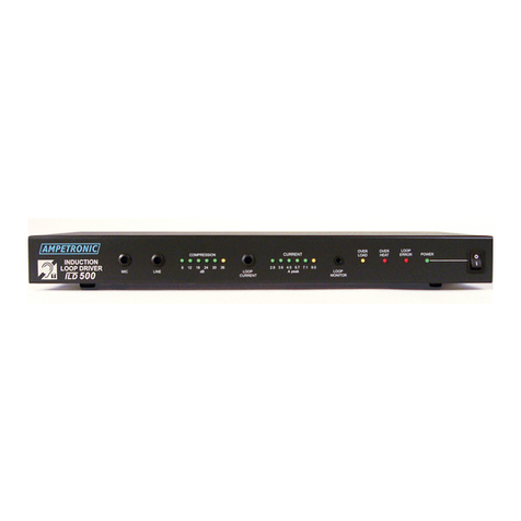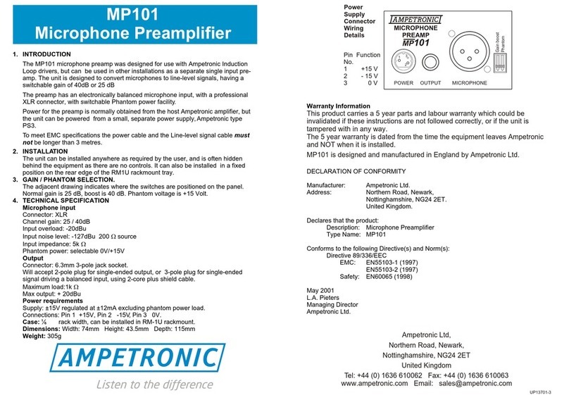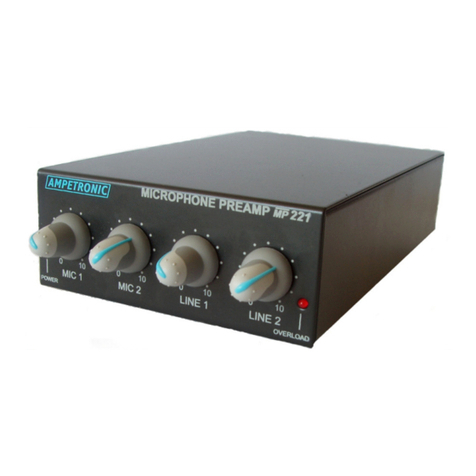
Microphone Inputs:
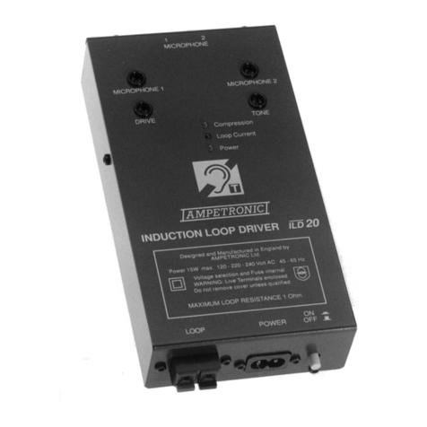
"Both inputs are designed to be used with an unbalanced microphone as
supplied with the equipment. Power for the microphone is supplied from
the equipment. Some unbalanced electret microphones with internal
battery can be externally powered if this internal battery is removed. Many
microphones of this type are adversely affected by the external DC power,
even when using their internal batteries. In all these instances, careful
investigation will indicate whether a microphone is suitable.
"Dynamic microphones cannot normally be used with the equipment,
because of the much lower signal level, also the DC bias seriously impairs
the performance of the microphone. Ampetronic can supply a special
adaptor which permits the use of dynamic microphones (and electrets
which are affected by the DC bias).
"The cable length on this input must not exceed 3 metres, as unbalanced
microphone lines are susceptible to interference. EMC compliance is only
met for this cable length. The above mentioned adaptor converts the input
to a balanced line, which can be extended to longer distances.
Line Input:
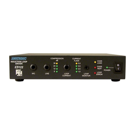
"A twin phono input is fitted to the unit, allowing a direct connection to the
Left and Right channels of the SCART signal, or the output from a HiFi
system. It is also possible to connect the line-level output of another
sound system to this input.
"Maximum cable length on this input should be less than 3 metres so as to
ensure EMC compliance.
Connection & Set-up:
During the initial commissioning of the equipment it is essential that the following
procedure be used to ensure a satisfactory end result.
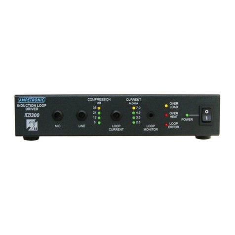
1. Turn the MICROPHONE, LINE and DRIVE controls fully anti-clockwise,
i.e. minimum signal, and set the TONE Control to mid-range position.
2. Provide a continuous input signal, preferably from a small tape/CD player
with speech or music, connected to the LINE input.
3. Increase the LINE control until the compression LED illuminates under
peak signal conditions. This establishes a reference level for the output
power driver.
4. Increase the DRIVE setting until the desired output current is achieved. If
no reading is obtained, check for loop continuity.

