AMPTRON Ai205 User manual

PDF created with FinePrint pdfFactorytrial version http://www.pdffactory.com

CopyRight 2002-2004 V2.0
This manual may not be reproduced in whole or in part by mimeogyaph
or any other means, without permission of Amptron.
The information contained in this document is believed to be accurate at
the time of publication, however, Amptron assumes no responsibility for any
errors which may appear here and reserves the right to make changes without
notice. Please ask the local represent for latest product specications before
ordering.
PDF created with FinePrint pdfFactorytrial version http://www.pdffactory.com

Please read this manual carefuly before doing installation,
operation and mantenance of Ai205.
Following symbols are used in this user,s manual and on meter
to alert the dangerous or to prompt in the operating or setting
process.
Dangerous symbol, Failure to observe the information may re-
sult in injury or death.
Alert symbol, Alert the potential dangerous.
Observ the information after the symbol to avoid possible in-
jury or death.
Installation and maintenance of the Ai205 meter should only be
performed by qualified, competent personnel that have appropriate
training and experience with high voltage and current device.
Ⅱ
PDF created with FinePrint pdfFactorytrial version http://www.pdffactory.com

Content
Copyright Ⅰ
Notice Ⅱ
Start Ⅲ
Content Ⅳ
Chapter 1 Introduction 1
The Purpose of Ai205 2
The Application Area of Ai205 4
The Function of Ai205 4
Ai205 Series 5
Chapter 2 Installation 7
Appearance and Dimensions 8
Installation Method 9
Wiring of Ai205 12
Chapter 3 Basic Operation and Setup 29
Display Panel and Keys 30
Metering Data Reading 32
Statistics Display 41
Meter Parameter Setting 44
Introduction of Measurement and Functions of Ai205 52
Chapter 4 Communication 61
Introducing Modbus Protocol 62
Format of the Communication 65
Address Table of Ai205 71
Appendix 93
Appendix A Technical Data and Specification 94
Appendix B Ordering 97
Ⅲ
PDF created with FinePrint pdfFactorytrial version http://www.pdffactory.com

Starting!
Congratulations!
You have got an advanced, Versitil, multifunction power meter. You may call
it a Remote terminal unit(RTU). It will benifit your power system.
When you open the package, you will find the following items.
1.Ai205 meter 1
2.14Pin terminal 1 (another for option)
3.Installation clips 4
4.User,s operation mannual 1
Please read this manual carefuly before operating or setting the Ai205 meter
to avoid unnecessary trouble.
You may read part of this manual depend on how you use the Ai205 meter.
Chapter 1 helps you to understand the fundamental function, specification
and application area of Ai205.
Chapter 2 describes in detail the installation and wiring of Ai205.
Chapter 3 tells you the data display and paramenter setting method of Ai205.
Chapter 4 gives the communiaction address table of Ai205.
Appendix lists the technical data and specifications of Ai205 and ordering
information.
Ⅳ
PDF created with FinePrint pdfFactorytrial version http://www.pdffactory.com

Chapter 1 Introduction
The purpose of Ai205
The Application Area of Ai205
The Function of Ai205
Ai205 Series
1
PDF created with FinePrint pdfFactorytrial version http://www.pdffactory.com

The Purpose of Ai205
Powerful Intelligent Power Meter
Ai205 Series Intelligent power meter was designed by used of latest
microprocessor and digital signal process technology. Electric power parameters,
energy and demands metering, power quality monitoring, remote control, over
range alarming, statistics and records, all these functions are only in one pocket-
size unit. There are also alarm on over/under Voltage, Current,Power, Power
Factor, Frequency, Unbalance Factors or Demands and Pulse Output based on
Energy or Reactive Energy in Ai205. Switch status monitoring is possible by
using the 4 digit inputs. It combines high accuracy measurement with intelligent
multifunction and simple HMI interface.
Idea Choice for Electric Automation SCADA System
Ai205 can be used to replace all traditional electric meters. It also can be
used as Remote Terminal Unit (RTU) for monitoring and controlling in a SCADA
system. All the measured data is available via digital RS485 communication ports
running the MobusTM protocol.
Energy Management
Ai205 can measure double directions four quadrants Kwh and Kvarh with
accuracy up to 0.5%. It can provide high standard energy data and energy demand
data. All these data is important for statistics of each line feeder and total.
Remote Power Control
The main function of Ai205 is measurement, but it has also got some flexible
I/O functions. This made the meter can be used as distributed RTU (metering,
monitoring, remote controlling in one unit).
2
PDF created with FinePrint pdfFactorytrial version http://www.pdffactory.com

Metering
PhaseVoltage: V1, V2, V3, Vlnavg
Line Voltage: V12, V23,V31,Vllavg
Current: I1, I2, I3, Iavg, In
Power: Power ofeach phase and total
Reactive Power:ReactivePower ofeach
phase and total
Apparent Power: ApparentPower of each
phase and total
Power Factor:Power factor of each phase
and average
Frequency
Statistics
Maximum value of statistics with time stamp
Mininum value of statistics with time stamp
Maximum of Demand
Communication
RS485 Communication port
Modbus RTUProtocol
Power Quality
THD, Even THD and Odd THD of phase/line
Voltage
Harmonics and Crest factor of phase/line
Voltage
THD, Even THD and Odd THD of Current
Harmonics and K Factor
Unbalance Factor of Voltage
Unbalance Factor of Current
Energyand Demand
Kwh of 4 quadrants: Import, Export, Total, Net
Kvarh of 4 quadrants: Import, Export, Total, Net
Demand of Power and Reactive Power
Remote Control
4 Digital Input (DI) (Wet or Dry)
2 RelayOutput
2 Digital Output (DO)
Power Quality Analysis
With the powerful digital signal processing ability the Ai205 intelligent power
meter can be used as an online power quality analysis instrument. It can
simultaneously and continuously give out the analysis results such as THD of
voltage and current, harmonics up to 31st and unbalance factor of voltage and
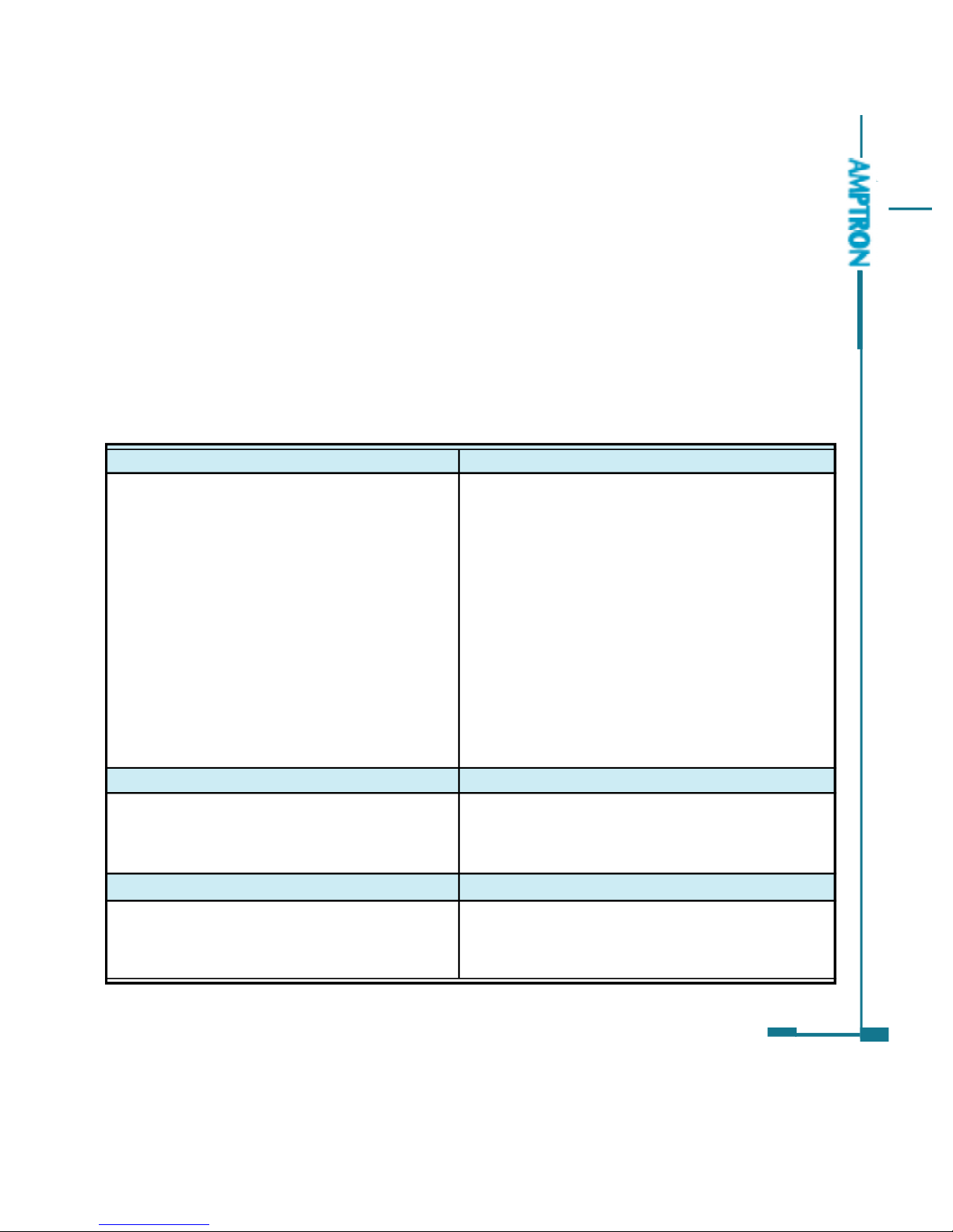
current, etc. The main function of Ai205 are listed in table1.1
3
Table 1.1 Main function of Ai205 series
PDF created with FinePrint pdfFactorytrial version http://www.pdffactory.com

4
The Application Area of Ai205
Power Distribution Automation Intelligent Electric Switch Gear
Industry Automation Building Automation
Energy Manage System Large UPS System
The Function of Ai205
Multifunction, High Accuracy
Ai205 Series Intelligent power meter was designed by use of latest
microprocessor and digital signal processing technology. Electric power
parameters metering, energy and demand recording, power quality monitoring,
remote controlling, over range alarming, statistics and records, all these functions
are only in one pocket-size unit. There are also basic alarm on over/under
Current, Voltage, Power, Power Factor, Frequency, Unbalance Factors or
Demands and Pulse Output based on Energy or Reactive Energy in Ai205. Status
monitoring is possible using the 4 digital inputs. It combines high accuracy
measurement with intelligent multifunction and friendly HMI interface.
Accuracy of Voltage and Current is 0.2%
Accuracy of Power and Energy is 0.5%
Small Size and Easy Installation
With the size of DIN96 96 and 55mm depth after mounting, the Ai205 can
be installed in a small cabin. The clips are used for easy installation and remove.
Easy to Use
By using of large screen high density LCD, the display of Ai205 is easy to
read and use. All the setting parameters can be access by using panel keys or
communication port. The setting parameters are protected in EEprom, which will
maintain its content after the meter is power off. With the backlight of the LCD,
PDF created with FinePrint pdfFactorytrial version http://www.pdffactory.com

5
the display can be easily read in the dim environment. The back light “on”time is
selectable.
Multiple Wiring Modes
In either high voltage or low voltage or three phase three wire or three phase
four wire or single phase system, the Ai205 can be easily used.
Ai205 series
The Ai205 series have two kinds of product, the standard Ai205 and the
advanced Ai205. Both these two products have multiple choice of I/O. Advanced
Ai205 has the basic measuring function of Ai205. It also gets extra function as
harmonics analysis, Max/Min record and over/under limit alarming.
Comparison of Ai205 Series
REAL TIME MEASURING
FUNCTION
Phase Voltage
Line Voltage
Current
Power
Reactive Power
Apparent Power
Power Factor
Frequency
Energy
Reactive Energy
Demand
Parameter
V1,V2,V3,Vlnavg
V12,V23,V31,Vllavg
I1,I2,I3,In,Iavg
P1,P2,P3,Psum
Q1,Q2,Q3,Qsum
S1,S2,S3,Ssum
PF1,PF2,PF3,PF
Frequency
Ep_imp,Ep_exp,Ep_total,Ep_net
Eq_imp,Eq_exp,Eq_total,Eq_net
Dmd_P,Dmd_Q,Dmd_S
P1
P2
METERING
ENERGY&
DEMAND
Table 1.2 Comparison ofAi205
P0
P3
PDF created with FinePrint pdfFactorytrial version http://www.pdffactory.com

6
1. There are two DIs in the basic Module of Ai205. The Option module can
provide additional 2 DIs, DI Auxilary Power, 2 DOs and 2 Relay Outputs.
2. The 2 DOs may be used as Alarm or Pulse output.
Note:
TIME
STATIS-
TICS
I/O
POWER QUALITY
MONITORINGOTHERS
ALARM
COMM
FUNCTION
Voltage Unbalance Factor
Current Unbalance Factor
Voltage THD
Current THD
Harmonics
Voltage Crest Factor
TIF
Current K factor
MAXwithTimeStamp
MIN withTime Stamp
Switch Status(DI)
Relay Output
Pulse Output
Over/Under Limit Alarm
RS485 Port
Real Time Clock
Parameter
U_unbl
I_unbl
THD_V1,THD_V2,
THD_V3,THD_Vavg
THD_I1, THD_I2,
THD_I3, THD_Iavg
Harmonics 2nd to 31st
Crest Factor
THFF
K Factor
ModbusTM Protocol
Year,Month,date,Hour,
minute,Second
P0
P3
P1
P2
PDF created with FinePrint pdfFactorytrial version http://www.pdffactory.com

Chapter 2 Installation
Appearance and Dimensions
Installation method
Wiring of Ai205
7
PDF created with FinePrint pdfFactorytrial version http://www.pdffactory.com

8
①
④
⑥
⑦
⑤
⑧
The installation method is introduced in this chapter. Please read this chapter
carefully before beginning installation work.
Appearance and Dimensions
Figure2.1 Appearance of Ai205
Table2.1 Part name of Ai205
Part Name
1. Enclosure
2. Front Casing
3. LCD Display
4. Key
5. Input Wiring Terminal
6.AuxiliaryWiring Terminal
7. Extend Wiring Terminal
8. Installation Clip
Description
The Ai205 enclosure is made ofhigh strength anti-
combustion engineering plastic
After the installation,thispartisinfront ofpanel. The
color ofthe frontcasing isselectable.
Large bright blue backlight LCDDisplay
Four keys are used to select displayand to set parameters
of the meter
Used for Voltage and Current input
Used for auxiliarypower, communication and DI
AuxiliaryI/O wiring terminals
When installation the clips are used for fixing the meter to
the panel
①
②
PDF created with FinePrint pdfFactorytrial version http://www.pdffactory.com

9
•Note
T h e i n s t a l l a t i o n
environment should
fulfill the temperature
and humidity that Ai205
meterrequires.Otherwise
it may cause the meter
damaged.
00.96
96.00
00.06
55.00
38.50
43.00
Dimensions
Front Side
Fig.2.2 Dimensions
Installation Method
Environmental
Please check the environment temperature and
humidity to ensure the satisfaction of Ai205 meter s
requirement before the meter installation.
Temperature
Operation: -20oC to 70oC
Storage: -40oC to 85oC
Humidity
5% to 95% non-condensing
Ai205 meter should be installed in dry and dust free environment and avoid
heat, radiation and high electrical noise source.
PDF created with FinePrint pdfFactorytrial version http://www.pdffactory.com

Installation Steps
Normally, Ai205 was installed on the panel of switch gear.
1. Cut a square hole on the panel of the switch gear.
The cutting size is as fig.2.3 Unit (mm)
Fig.2.3 Panel Cutting
2. Remove the clips from the meter and insert the meter into the square hole
from the front side.
Fig.2.4 Put the meter into the square hole
3. Put clips back to the meter from the backside and push the clip tightly so
that the meter is fixed on the panel.
10
+0.5
-0.0
90
+0.5
-0.0
90
Panel
Cut
Panel
PDF created with FinePrint pdfFactorytrial version http://www.pdffactory.com

Fig 2.6 Space around the meter
Space required for Installation
The space around the meter should be large enough so that the meter
removing, terminal strip wiring and wire arrangement could be done easily. The
recommend minimum space around the meter is show in Table2.2 and Fig.2.6.
11
Environment
Temperature
<50℃
≥50℃
Table 2.2 Minimum Space
Minimum Distance(mm)
a b c d e f g
25 25 38 38 64 25 25
38 38 51 51 76 38 38
d
c
e
ba
fg
Fig.2.5 Use the clips to fasten the meter on the panel
Panel
Panel
Panel
PDF created with FinePrint pdfFactorytrial version http://www.pdffactory.com

Wiring of Ai205
Terminal Strips
There are three terminal strips on the back of Ai205, Voltage & Current Input
Terminal Strip, Auxiliary Terminal Strip and Extend Terminal Strip. Only the Ai205
with PRIO option has the Extend Terminal Strip. The 1, 2 and 3 are used to
represent each phase of three phase system. They have the same meaning
with A, B and C or R, S and T in three phase system.
12
Voltage & Current Input Terminal Strip
Auxiliary Terminal Strip
Note: NC means No Connection
Extend Terminal Strip
Fig 2.7 Terminal Strips
Aux.
PDF created with FinePrint pdfFactorytrial version http://www.pdffactory.com

Safety Earth Connection
Before doing the meter wiring connection, please make
sure that the switch gear has a safety Earth system.
Connect the meter safety earth terminal to the switch gear
safety earth system.
The following safety earth symbol is used in the user s
manual.
Auxiliary Power
The auxiliary power supply of the Ai205 meter is 85-
264Vac (50/60Hz) or 100-300Vdc. Typical power
consumption of the meter is less than 2W. A regulator or a
UPS should be used when the power supply undulates
too much. The terminals for the auxiliary power supply are 20, 22 and 24 (L, N,
G).
A fuse (typical 1A/250Vac) should be used in auxiliary power supply loop.
No. 24 terminal must be connected to the safety earth system of switchgear.
An isolated transformer or EMI filter should be used in the auxiliary power
supply loop if there is power quality problem in the power supply.
13
•Note
Make sure the auxiliary
power terminal of the
meter G is connected to
t h e s a f e t y E a r t h o f
switchgear.
•Note
Make sure the voltage of
power supply is the same
as what the meter needed
for its auxiliary power.
DANGEROUS
O n l y t h e q u a l i f i e d
personnel could do the
wire connection work.
Make sure the power
supply is cut off and all
the wires are electroless.
Failure to observe it may
result in severe injury or
death.
Power Supply
85~264Vac
1A FUSE
Ai205
L
N
G
20
22
24
Fig 2.8 Power supply
Ground
PDF created with FinePrint pdfFactorytrial version http://www.pdffactory.com

The choice of wire of power supply could be AWG16-22 or 0.6-1.5mm2
Voltage Input
Two Voltage Input options of Ai205 are 100Vac and 400Vac.
100Vac option is suitable for low voltage system that less than 120Vac or
high or medium voltage system that the secondary of PT is 100Vac. The input
voltage V1, V2 and V3 against Vn of Ai205 should be less than 120Vac if the
100Vac option is selected.
400Vac option is suitable for low voltage system that less than 480Vac. The
voltage input could be directly connected to the terminal of Ai205 without the use
of PT. The input voltage V1, V2 and V3 against Vn of Ai205 should be less than
480Vac. If the input voltage is higher than 480Vac, the PT should be used.
A fuse (typical 1A/250Vac) should be used in voltage
input loop.
PT should be used to transform the high voltage into
measurement range of Ai205 if it is used in high voltage system.
The wire number of voltage input could be AWG16-22
or 0.6-1.5mm2
Note:In no circumstance could the secondary of PT be shorted. The secondary of PT should
•Note
A filter should be used
if there is EMI problem
•Note
The secondary of PT
can not be shorted,
otherwise it may cause
the severe damage of
the instrument.
14
Fig.2.9 Wiring of Auxiliary Power supply under EMI
Power Supply
85~264Vac
1A FUSE
Ai205
L
N
G
20
22
24
L
N
G
L
N
G
Power
filter
Ground
be well grounded.
PDF created with FinePrint pdfFactorytrial version http://www.pdffactory.com

Current Input
In a practical engineering application, CTs should be installed in the loop of
measuring. Normally the secondary of CT is 5A. 1A is possible in the ordering
option. A CT of accuracy over 0.5% (rating over 3VA) is recommended and it will
influence the measuring accuracy. The wire between CT and Ai205 should be
as shorter as possible. The length of the wire may increase the error of the
measurement.
The wire number of current input could be AWG15-16 or 1.5-2.5mm2
The CT loopshould notbe opencircuit inanycircumstance when
thepower ison. Thereshould not beanyfuse or switchin the CTloop
and one end of the CT loopshould be connectedto the ground.
Vn Connection
Vn is the reference point of Ai205 voltage input. The lower is wire resistance
the less is the error.
Three phase wiring diagram
Ai205 can satisfy almost all kinds of three phase wiring diagram. Please read
this part carefully before you begin to do the wiring so that you may chose a
wiring diagram suitable for your power system.
The voltage and current input wiring mode can be set separately in the meter
parameter setting process. The voltage wiring mode could be 3 phase 4 line Wye
mode (3LN), 3 phase 4 line 2PT Wye mode (2LN) and 3 phase 3 line open Delta
mode (2LL). The current input wiring mode could be 3CT, 2CT and 1CT. Any
voltage mode could be group with one of the current mode.
15
PDF created with FinePrint pdfFactorytrial version http://www.pdffactory.com
Table of contents