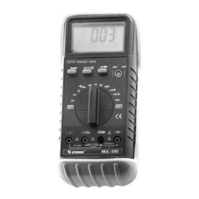
Steren MUL-300 User manual


ENGLISH
ENGLISH-2
Before using your new Professional Multimeter, please read
this instruction manual to prevent any damage. Put them
away in a safe place for future references.
SECURITY INFORMATION
This multimeter has been designed according to IEC-1010
specifications for electronic testing equipment.
When using your multimeter, observe the following safety rules:
Protection against damages caused by electrical current.
Protection against damages caused by inadequate use.
The testing points meet all safety standards, if you need to
replace these make sure the new testing points have the
same characteristics or are the same model points.
Never exceed the indicated limits in each measuring range.
When the multimeter forms a bridge with the circuit that is to
be measured, don’t touch the points that are being used to
measure.
When you don’t know the range of the equipment to be
measured, set the dial to the highest range possible.
Before adjusting the dial to a different range or a different
function, disconnect the testing points from the multimeter.
When you break the power circuits, remember that the
voltage amplitude pulses can be higher than normal, and
this pulses can damage the meter.
Never measure resistance, capacity, inductance, diode, or
continuity on live circuits.
Whenever measuring voltages above 60 VDC or 30 VAC
rms, place your fingers above the protection rings on the
testing points.
Do not store or use this meter in places exposed to direct
sun light, high temperatures, humidity or condensation.
MAINTENANCE
1.- Before opening your multimeter, always disconnect the
testing points from the multimeter’s source of electrical current.
2.- For an effective protection against fire, always replace a fuse
with one that has the same characteristics in voltage and current:
15A / 250V.
•
•
•
•
•
•
•
•
•
•
•
Before usin
g
y
our new Professional Multimeter, please read
t
his instruction manual to prevent an
y
dama
g
e. Put them
a
wa
y
in a safe place for future references
.

ENGLISH
ENGLISH-3
3.- If you notice any kind of malfunction or abnormality, stop all
use of your multimeter until it is checked by authorized
personnel.
4.- Never use your multimeter if the protective cover is not
properly placed.
5.- Clean your multimeter periodically with a clean humid rag and
soft detergent. Never use solvents or abrasives in order to clean
your multimeter.
6.- If the multimeter is going to be stored without use for an
extended period of time, remove the batteries in order to prevent
damage to your multimeter.
DESCRIPTION
This multimeter is a professional instrument.
3 ½ digit LCD screen, 28 mm tall, with polarity indicator and
readings up to 1999 counts.
DC voltage measurements
AC voltage measurements
DC Amps measurement
AC Amps measurement
Temperature measurement
Resistance measurement
Capacity measurement
Diodes measurement
Audible continuity test
On / Off button
Light button (5 seconds length)
Hold button
RANGE FUNCTION AND SELECTOR
This multimeter is a professional, portable instrument, with a
large LCD screen for an easy reading. It has special
characteristic, in order to avoid a bad connection of the testing
points. The input female jacks (red colour) are made specially
for functions and ranges. Using a mechanic block system, it will
allow us to choose the right position of the testing points.
If the testing points are plugged and you turn the dial, you
cannot perform the operation until you remove the red testing
point. Then first, remove the point and then set the dial in the
required range, after that, replace the testing point in the
available connector (the others are blocked)
•
•
•
•
•
•
•
•
•
•
•
•
•
•

ENGLISH
ENGLISH-4
The dial allow us to choose the range and the function to be
measured.
GENERAL SPECIFICATIONS
PRECISION
This unit is specified for a one year period in 64ºF to 82 º F
temperatures and 75% relative humidity.
Operation temperature: 32ºF to 104ºF
Input: 9V (alkaline or carbon zinc battery) (1x9V)
Maximum voltage between connectors and ground:
1000VDC or VAC (peak value).
Includes 30 ranges for all scales.
Protection against over range, for all ranges.
LCD screen, 1999 counts, 3 1/2 digits, 28mm tall
Over range indicator: “1” or “-1”
Polarity indicator: “ – “
Low battery indicator
Approximate time for sample request: 0,4seconds
Temperature factor: < 0,1 x accuracy/ ºC
Operation altitude: 7000ft maximum
Dimensions: 191 x 82 x 36 mm
Weight : 380g including battery and case
DC VOLTAGE
10Mohms input impedance, in all ranges
Protection against over range:
in 200mV range: 250VDC or VAC rms
In 2 to 1000V range: 1000VDC or 700VAC rms
•
•
•
•
•
•
•
•
•
•
•
•
•
•
Ran
g
e Resolution Accurac
y
200mV 0,1mV ±0,5 % of rgd ± 1d
2V 1mV ±0,5 % of rgd ± 3d
20V 10mV ±0,5 % of rgd ± 3d
200V 100mV ±0,5 % of rgd ± 3d
1000V 1V ±0,8 % of rgd ± 3d

In the smallest voltage range, the meter may display an
unstable reading, specially when the testing leads have
not reached the circuit , this is normal because of the high
sensitivity of the meter. When the testing points touched the
circuit, you will get a true reading.
AC VOLTAGE
10Mohms input impedance, in all ranges
Protection against over range:
in 200mV range: 250VDC or VAC rms
in 2 to 1000V range: 1000VDC or 700VAC rms
Response: Average response, calibrated in sine wave rms
Frequency: 40 to 400Hz
Test in 60/50Hz
In the smallest voltage range, the meter will show an
unstable reading, specially when the testing leads have
not reached the circuit , this is normal because of the high
sensitivity of the meter. When the testing points touched the
circuit, you will get a true reading.
DC AMPS
Protection against over charge:
In 2mA to 200mA range: F1: 200mA / 250V fuse
in 10A range: F2: 10A / 250V
Maximum current input: mA connector: 200m
10A connector: 10A
Voltage loss: 200mV
ENGLISH
ENGLISH-5
Ran
g
e Resolution Accurac
y
2V 1mV ±1,0 % of rgd ± 5d
20V 10mV ±1,0 % of rgd ± 5d
200V 100mV ±1,0 % of rgd ± 5d
1000V 1V ±1,2 % of rgd ± 5d
Ran
g
e Resolution Accurac
y
2mA 1A ±1,0 % of rgd ± 3d
20mA 10A ±1,0 % of rgd ± 3d
200mA 100A ±1,5 % of rgd ± 5d
10A 10mA ±2,0 % of rgd ± 10d
I
n t
h
e sma
ll
est vo
l
ta
g
e ran
g
e, t
h
e meter ma
y
di
sp
l
a
y
an
u
nstable readin
g
, speciall
y
when the testin
g
leads have
not reached the circuit , this is normal because of the hi
g
h
s
ensitivit
y
of the meter. When the testin
g
points touched the
c
ircuit,
y
ou will
g
et a true readin
g.
I
n t
h
e sma
ll
est vo
l
ta
g
e ran
g
e, t
h
e meter w
ill
s
h
ow an
u
nstable readin
g
, speciall
y
when the testin
g
leads have
not reached the circuit , this is normal because of the hi
g
h
s
ensitivit
y
of the meter. When the testin
g
points touched the
c
ircuit,
y
ou will
g
et a true readin
g.

AC AMPS
Protection against over charge:
in 2mA to 200mA range: F1: 200mA / 250V fuse
In 10A / 250V range
Maximum current input: mA connector:200mA
10A connector : 10A
Voltage loss : 200mV
Frequency: 40 to 400Hz
Test in 60 / 50Hz
Response: Average response, calibrated in sine wave rms
RESISTANCE (ohms)
Maximum voltage in an open circuit:
in 20Mohm range: 3,0V
Other ranges: <700mV
Protection against over charge: 250VDC or VCA rms in all
ranges
CAPACITANCE
ENGLISH
ENGLISH-6
Ran
g
e Resolution Accurac
y
2mA 1A ±1,2 % of rgd ± 5d
200mA 0,1mA ±2,0 % of rgd ± 5d
10A 10mA ±3,0 % of rgd ± 10d
Ran
g
e Resolution Accurac
y
200Ohms 0,1Ohms ±1,0 % of rgd ± 10d
2000ohms 1Ohm ±1,0 % of rgd ± 1d
20kOhms 10Ohms ±1,0 % of rgd ± 1d
200kOhms 100Ohms ±1,0 % of rgd ± 1d
2Mohms 1kOhm ±1,0 % of rgd ± 1d
20Mohms 10kOhms ±1,0 % of rgd ± 5d
Ran
g
e Resolution Accurac
y
2nF 1pF ±4,0 % of rgd ± 3d
20nF 10pF ±4,0 % of rgd ± 3d
200nF 0,1pF ±4,0 % of rgd ± 3d
2F 1nF ±4,0 % of rgd ± 3d
20F 10nF ±4,0 % of rgd ± 3d

TEMPERATURE
Protection against over charge: 250VDC or VAC rms
AUDIBLE CONTINUITY TEST
Protection against over charge: 250VDC or VAC rms
Voltage in an open circuit: 2,8V approx.
TESTING DIODES
Protection against over charge: 250VDC or VAC rms
Approximate ADC in direct polarization: 1mA
Approximate VDC in inverted polarization; 2,8V
FREQUENCY
Protection against over charge: 250VDC o VAC rms
Sensitivity: 200mV rms and <10Vrms input
ENGLISH
ENGLISH-7
Ran
g
e Resolution Accurac
y
-20ºC a 0ºC 1°C ±5,0 % of rgd ± 5d
0°C to 400°C 1°C ±1,0 % of rgd ± 3d
401°C to 1000°C 1°C ±2,0 % of rgd ± 3d
Function Description
The buzzer sounds if the resistence is under 70 ohm
Function Resolution
1mV Approximate reading of the diode voltage
in direct polarization
Description
Ran
g
e Resolution Accurac
y
20kHz 10Hz ±1,5 % of rgd ± 10d
)))

INSTRUCTIONS
HOLD BUTTON
If you need to maintain a value in the screen, press the button
marked with an H, then the current value will be displayed in the
screen, until you press the button H, once again.
LIGHT BUTTON
Press this button if you want to turn the backlight on, specially
when you do measures at nite. Press the button with the icon of
a sun and the backlight will turn on for 5 seconds (this light con-
sume many energy, just use it in special conditions).
If the battery voltage is under 7 volts, in the screen will display a
battery icon, but if you use the backlight at the same time, after
it turn off, the battery icon may disappear, because the voltage
down.
MEASUREMENT METHODS
MEASURING DC / AC VOLTAGE
1.- Connect the red testing point to the jack signaled “V ” and
the black testing point to the jack signaled “COM”.
2.- Set the dial to the VDC / VAC setting
3.- Connect the testing points to the equipment to be measured.
4.- Turn the equipment to be measured on, the voltage will ap-
pear on the LCD screen. The polarity will also appear.
MEASURING DC / AC AMPS
1.- Connect the red testing point to the jack signaled “mA” when
measuring up to 200 mA, and to the jack signaled “A” when
measuring above, and the black testing point to the jack signaled
“COM”.
2.- Set the dial to the VDC or VAC setting .
3.- Open the circuit to be measured and connect the testing
points (serial) where the current must be measured.
4.- Read the current value in the screen.
For resistance over 1Mohm, the meter can be delayed for
few seconds, this is normal because of the high value of the
resistance.
ENGLISH
ENGLISH-8
For resistance over 1Mohm, the meter can be dela
y
ed for
f
ew seconds, this is normal because of the hi
g
h value of the
resistance
.

When the input is not connected, the “1” will be displayed in
the screen, indicating overcharge.
Remember to fully discharge the energy from the capacitors
and the circuit, when you measure resistance inside of a
circuit.
MEASURING CAPACITY
1.- Connect the red testing point to the jack signaled “V ” and
the black testing point to the jack signaled “COM”.
2.- Set the dial to the “nF” or “F” range.
3.- Before inserting the capacitor in the capacitor jack, make sure
that it has been completely discharged and make sure to respect
polarity.
4.- Read the value in the screen.
In the smallest range of capacity, the reading will includes a
small value for testing points influence. But this won’t affect
the accuracy of the reading.
For higher capacity, the meter will take more time to
stabilize the reading.
MEASURING TEMPERATURE
1.- Set the dial to TEMP range.
2.- Connect the thermo pair type K into the meter (same
connector for ”V“ and ”COM“), then use the tip to touch the
object to be measured.
3.- Read the value in the screen.
TESTING AUDIBLE CONTINUITY
1.- Connect the red testing point to the jack signaled “V ” and
the black testing point to the jack signaled “COM”.
2.- Set the dial to ))) range, and the button in ))) position.
3. Connect the testing points to the circuit to be measured. If the
resistance is under 70Ohms, the buzzer will sound.
MEASURING DIODES
1.- Connect the red testing point to the jack signaled “V ” and
the black testing point to the jack signaled “COM”.
2.- Set the dial to range.
3.- Connect the red testing point to the diode to be measured
and the black testing point to the cathode.
4.- The voltage will appear on the LCD screen in m Volts.
ENGLISH
ENGLISH-9
W
hen the input is not connected, the “1” will be displa
y
ed in
t
he screen, indicatin
g
overchar
g
e
.
Remember to full
y
dischar
g
e the ener
gy
from the capacitors
a
nd the circuit, when
y
ou measure resistance inside of a
c
ircuit
.
I
n the smallest ran
g
e of capacit
y
, the readin
g
will includes a
s
mall value for testin
g
points influence. But this won’t affect
t
he accurac
y
of the readin
g.
For hi
g
her capacit
y
, the meter will take more time to
s
ta
bili
ze t
h
e rea
di
n
g.

MEASURING FREQUENCY
1.- Connect the red testing point to the jack signaled “V ” and
the black testing point to the jack signaled “COM”.
2.- Set the dial to 20kHz range.
3.- Connect the testing points to the circuit to be measured.
4.- The frequency will appear on the LCD screen.
Measures over 10V rms are allowed, but the accuracy is not
guaranteed.
WARNING
Before removing the cover from your multimeter, make sure the
testing points are disconnected to avoid the risk of electrical
shock.
REPLACING THE BATTERY AND THE FUSE
The fuse rarely needs to be replaced and when it does, it is usu-
ally due to an error in operation.
If “BAT” appears on your LCD screen, the battery needs to be
replaced.
To replace the fuse ( F1: 200 mA / 250 V y F2: 10 A / 250 V ) or
the battery remove the cover from the multimeter removing the
three screws on the back of the multimeter. Replace the fuse
and/or battery and replace the cover on your multimeter.
HOLDER
Place the holder up to three different positions, in order to obtain
an easy LCD reading.
ACCESSORIES
User’s manual
Testing points
Battery
Thermo pair type K
Case
The characteristics for this multimeter are subject to change
without notice.
•
•
•
•
•
ENGLISH
ENGLISH-10
M
easures over 10V rms are allowed, but the accurac
y
is not
g
uarantee
d.
T
he characteristics for this multimeter are sub
j
ect to chan
ge
w
ithout notice
.


ESPAÑOL
Antes de utilizar su nuevo Multímetro Profesional, lea
este instructivo para evitar cualquier mal funcionamiento.
Guárdelo para futuras referencias.
INFORMACION DE SEGURIDAD
Este Multimetro ha sido diseñado de acuerdo con la Norma
IEC-1010 aplicable a instrumentos electrónicos de medición.
Cuando use su multimetro, debe Ud. observar las siguientes
Reglas de seguridad:
Protección contra daños por corriente eléctrica.
Protección del multimetro contra mal uso
Las puntas de prueba cumplen con estándares de
seguridad, si necesita reemplazarlas que sea con unas de
las mismas características o mismo modelo 1000 V 10 A
Nunca exceda los límites de valor indicados en cada rango
de medición.
Cuando el multimetro forma un puente con el circuito a
medir no toque las terminales de las puntas de prueba.
Cuando el valor de la escala a medir es desconocido,
coloque el selector de rango en la posición más alta.
Antes de girar el selector de rango a diferentes escalas o
función, desconecte las puntas de prueba del circuito.
Nunca conecte las puntas de prueba del multimetro
atravesando una fuente de poder mientras el
interruptor giratorio este en posición de corriente,
resistencia, diodo o continuidad. Hacerlo puede dañar el
multimetro.
Cuando lleve hacia fuera las mediciones en TV´s o
interrumpa los circuitos de poder, siempre recuerde que
los pulsos de amplitud de voltaje pueden ser muy altos, lo
cual puede dañar el multimetro.
Nunca mida resistencia en circuitos vivos ( alimentados ).
Siempre que mida voltajes arriba de 60 VCD o 30 VCA rms,
ponga los dedos por encima de los anillos de protección
(barril) de las puntas de prueba.
No almacene ni use su multimetro en ambientes expuestos
directamente a la luz de sol, altas temperaturas, exceso de
humedad o condensación.
•
•
•
•
•
•
•
•
•
•
•
•
•
ESPAÑOL-2
A
ntes de utilizar su nuevo Multímetro Profesional, lea
e
ste instructivo
p
ara evitar cual
q
uier mal funcionamiento.
G
uárdelo
p
ara futuras referencias
.

ESPAÑOL
ESPAÑOL-3
MANTENIMIENTO
1. Antes de abrir el multimetro, siempre desconecte las puntas
de prueba de las fuentes de corriente eléctrica.
2. Para una protección efectiva contra fuego, siempre reemplace
el fusible por uno de las mismas especificaciones en voltaje y
corriente : F1 = 200 mA / 250 V ( fusión rápida ), F2 = 10 A / 250
V (fusión rápida)
3. Si nota cualquier falla o anormalidad, el multimetro no debe
usarse hasta no ser revisado por personal autorizado, no intente
ajustarlo ni repararlo si no tiene los conocimientos para ello.
Llame al técnico calificado.
4. Nunca use el medidor si la cubierta protectora no esta puesta
adecuadamente en su lugar.
5. Para limpiar el multimetro utilice un trapo húmedo y
detergente suave, no utilice abrasivos y/o solventes.
6. Si el multimetro va a ser almacenado por un período de
tiempo largo, las baterías deben removerse para evitar que
dañen el multimetro.
DESCRIPCION
El multimetro es un instrumento profesional:
Pantalla de 3 1/2 digitos LCD, números de 28 mm altura,
con indicador de polaridad, lectura hasta 1999 cuentas.
Medición de voltaje de corriente directa
Medición de voltaje de corriente alterna
Medición de Amperaje de corriente directa
Medición de Amperaje de corriente alterna
Medición de temperatura
Medición de resistencia
Medición de capacidad
Probador de diodos
Probador de continuidad audible
Interruptor Encendido / Apagado
Botón de iluminación (duración de 5 segundos)
Botón de retención de datos ( Hold )
FUNCION Y SELECTOR DE RANGO
Este es un multimetro Profesional portátil de pantalla grande de
cristal liquido ( LCD ) y fácil lectura.
Este multimetro posee la característica de evitar una mala
conexión de las puntas de prueba, Los conectores hembra
(jacks) de entrada para la punta de prueba roja tienen un
•
•
•
•
•
•
•
•
•
•
•
•
•
•

ESPAÑOL
arreglo adecuado a las funciones y rangos. Esto es mediante un
bloqueo mecánico que nos permite seleccionar adecuadamente
la posición de las puntas de prueba. Dicho de otra manera, si
las puntas de prueba están colocadas y Ud. gira el selector de
funciones, este no girará hasta que quite Ud. la punta de prueba
roja, seleccione la función a medir y entonces coloque la punta
en el contacto único disponible ( los otros están bloqueados ).
El interruptor selector nos permite elegir el rango así como la
función a medir.
ESPECIFICACIONES GENERALES
PRECISION
Esta especificada para un periodo de un año en condiciones de
18ºC a 28ºC ( 64ºF a 82ºF )con humedad relativa de 75%
Temperatura de operación: 0 a 40ºC ( 32ºF a 104ºF )
Alimentación: Batería de 9 V alcalina o carbón zinc. (1 x 9 V)
Voltaje máximo entre terminales y tierra: 1000 VCD o VCA
(valor pico)
Incluye 30 rangos en sus escalas
Protección de sobrerango para todos los rangos
Pantalla: Cristal líquido ( LCD ), 1999 cuentas, 3 1/2 dígitos y 28
mm de altura
Indicación de sobrerango ”1” o “-1”
Indicador de polaridad: ”–“
Indicador de bateria baja
Tiempo aproximado de toma de muestra: 0,4 segundos
Factor de temperatura: < 0,1 x exactitud/ ºC
Operación a altitud máxima de: 2000 m ( 7000 ft ) máximo
Dimensiones: 191 x 82 x 36 mm
Peso: 380 g incluye batería y funda.
VOLTAJE DE CD
Impedancia de entrada de 10MOhm en todos los rangos
Protección contra sobrecarga: en rango de 200 mV: 250 VCD
o VCA rms en rango de 2 a 1000 V: 1000 VCD o 700 VCA rms
ESPAÑOL-4
Ran
g
o Resolución Precisión
200mV 0,1mV ±0,5 % de rgd ± 1d
2V 1mV ±0,5 % de rgd ± 3d
20V 10mV ±0,5 % de rgd ± 3d
200V 100mV ±0,5 % de rgd ± 3d
1000V 1V ±0,8 % de rgd ± 3d

En el rango de pequeño voltaje, el medidor mostrará
inestabilidad en la lectura mostrada cuando las puntas de
prueba no han alcanzado el circuito ( hecho contacto ), esto
es normal debido a la gran sensibilidad del medidor.
Cuando las puntas de prueba han hecho contacto con el
circuito Ud. puede obtener una lectura verdadera.
VOLTAJE DE CA
Impedancia de entrada de 10MOhms
Protección contra sobrecarga: en rango de 200 mV: 250 VCD
o VCA rms
en rango de 2 a 1000 V: 1000 VCD o 700 VCA rms
Respuesta: Respuesta promedio, calibrado en rms de onda
senoidal
Frecuencia: 40 a 400 Hz
Prueba en 60/50 Hz
En el rango de pequeño voltaje, el medidor mostrará
inestabilidad en la lectura mostrada cuando las puntas de
prueba no han alcanzado el circuito ( hecho contacto ), esto
es normal debido a la gran sensibilidad del medidor.
Cuando las puntas de prueba han hecho contacto con el
circuito Ud. puede obtener una lectura verdadera.
AMPERAJE DE CD
Protección contra sobrecarga:
En rango de 2 mA a 200 mA: F1: fusible de 200 m A/ 250 V
En rango de 10 A: F2: 10 A / 250 V
Máxima entrada de corriente: Conector mA: 200 m
Conector 10 A: 10 A
Caída de voltaje: 200 mV
ESPAÑOL-5
ESPAÑOL
Ran
g
o Resolución Precisión
2V 1mV ±1,0 % de rgd ± 5d
20V 10mV ±1,0 % de rgd ± 5d
200V 100mV ±1,0 % de rgd ± 5d
1000V 1V ±1,2 % de rgd ± 5d
Ran
g
o Resolución Precisión
2mA 1A ±1,0 % de rgd ± 3d
20mA 10A ±1,0 % de rgd ± 3d
200mA 100A ±1,5 % de rgd ± 5d
10A 10mA ±2,0 % de rgd ± 10d
E
n el ran
g
o de pequeño volta
j
e, el medidor mostrará
i
nestabilidad en la lectura mostrada cuando las puntas de
p
rueba no han alcanzado el circuito
(
hecho contacto
)
, esto
e
s norma
l
d
e
bid
o a
l
a
g
ran sens
ibilid
a
d
d
e
l
me
did
or.
C
uando las puntas de prueba han hecho contacto con el
c
ircuito Ud.
p
uede obtener una lectura verdadera
.
E
n el ran
g
o de pequeño volta
j
e, el medidor mostrará
i
nestabilidad en la lectura mostrada cuando las
p
untas de
p
rueba no han alcanzado el circuito
(
hecho contacto
)
, esto
e
s normal debido a la
g
ran sensibilidad del medidor.
C
uando las
p
untas de
p
rueba han hecho contacto con el
ci
rcu
i
to
Ud
.
p
ue
d
e o
b
tener una
l
ectura ver
d
a
d
era
.

AMPERAJE DE CA ( A~ )
Protección contra sobrecarga:
En rango de 2 mA: a 200 mA: F1: fusible de 200 m A/ 250 V
En rango de 10 A / 250 V
Máxima entrada de corriente: Conector mA: 200 mA
Conector 10 A: 10 A
Caída de voltaje: 200 mV
Frecuencia: 40 a 400 Hz
Prueba en 60/50 Hz
Respuesta: Respuesta promedio, calibrado en rms de onda
senoidal
RESISTENCIA ( Ohms )
Voltaje máximo en circuito abierto:
En el rango de 20 MOhms 3,0 V
Otros rangos < 700 mV
Protección contra sobrecarga: 250 VCD o VCA rms en todos los
rangos
CAPACITANCIA
ESPAÑOL
ESPAÑOL-6
Ran
g
o Resolución Precisión
2mA 1A ±1,0 % de rgd ± 3d
20mA 10A ±1,0 % de rgd ± 3d
200mA 100A ±1,5 % de rgd ± 5d
10A 10mA ±2,0 % de rgd ± 10d
Ran
g
o Resolución Precisión
200Ohms 0,1Ohms ±1,0 % de rgd ± 10d
2000ohms 1Ohm ±1,0 % de rgd ± 1d
20kOhms 10Ohms ±1,0 % de rgd ± 1d
200kOhms 100Ohms ±1,0 % de rgd ± 1d
2Mohms 1kOhm ±1,0 % de rgd ± 1d
20Mohms 10kOhms ±1,0 % de rgd ± 5d
Ran
g
o Resolución Precisión
2nF 1pF ±4,0 % de rgd ± 3d
20nF 10pF ±4,0 % de rgd ± 3d
200nF 0,1pF ±4,0 % de rgd ± 3d
2F 1nF ±4,0 % de rgd ± 3d
20F 10nF ±4,0 % de rgd ± 3d

TEMPERATURA
Protección contra sobre carga: 250 VCD o VCA rms
PRUEBA DE CONTINUIDAD AUDIBLE
Protección contra sobre carga: 250 VCD o VCA rms
Voltaje en circuito abierto: 2,8 V aprox.
PRUEBA DE DIODOS
Protección contra sobre carga: 250 VCD o VCA rms
ACD aproximada en polarización directa: 1 mA
VCD aproximado en polarización inversa: 2,8 V
FRECUENCIA
Protección contra sobre carga: 250 VCD o VCA rms
Sensibilidad: 200 mV rms y entrada < 10 Vrms
ESPAÑOL
ESPAÑOL-7
Ran
g
o Resolución Precisión
-20ºC a 0ºC 1°C ±5,0 % de rgd ± 5d
0°C a 400°C 1°C ±1,0 % de rgd ± 3d
401°C a 1000°C 1°C ±2,0 % de rgd ± 3d
Función
El zumbador suena si la resistencia es menor a 70 Ohms
Descripción
)))

INSTRUCCIONES DE OPERACION
BOTÓN DE RETENCIÓN DE DATOS
Si Ud. necesita congelar un dato cuando mide, Ud. puede
oprimir el botón marcado con H y este dato permanecerá en la
pantalla, si oprime el botón H de nuevo este dato se borrará.
BOTÓN DE ILUMINACIÓN DE LA PANTALLA
Si necesita Ud. realizar alguna medición en la obscuridad, Ud.
puede oprimir el botón marcado con un sol y la pantalla se
iluminará solo por 5 segundos, debido a que el foco consume
demasiada corriente, así se evita que se consuma la batería.
Cuando el voltaje de la batería sea menor de 7 Volts, aparecerá
en la pantalla el símbolo de la batería, pero si esta Ud. usando
al mismo tiempo la iluminación de la pantalla es posible que
cuando deje de utilizar esta iluminación el símbolo de batería se
apage; esto es debido a que cuando Ud. utiliza la iluminación se
consume alta corriente, entonces el voltaje se cae.
METODO DE MEDICION
MEDICION DE VOLTAJE DE CD O CA
1. Conecte la punta de prueba roja al conector hembra ( Jack )
marcado como ”V “, la punta negra al conector hembra ( Jack )
marcado como ”COM“.
2. Fije el selector giratorio en la escala de VCD/CA en el rango
deseado.
3. Conecte las puntas de prueba al dispositivo o circuito e inicie
la medición.
4. Encienda el dispositivo o circuito que va a medir, el valor del
voltaje aparecerá en la pantalla (display) digital. La polaridad
aparecerá cuando medimos corriente directa.
MEDICION DE AMPERAJE DE CD O CA
1. Coloque la punta de prueba roja en la posición ”mA“ y la
negra en la posición ”COM“ (para mediciones máximas de 200
mA; para medir 10 A coloque la punta roja en donde indica 10A)
2. Coloque el selector giratorio en la posición de DC o AC en el
rango deseado.
3. Abra el circuito a ser medido y conecte las puntas de prueba
en SERIE con la carga en donde la corriente debe ser medida.
4. Lea el valor de la corriente en la pantalla ( display ) digital. La
polaridad aparecerá si medimos corriente directa.
ESPAÑOL
ESPAÑOL-8

MEDICION DE RESISTENCIA
1. Coloque la punta roja en ”V “ y negra en ”COM“
2. Coloque el selector giratorio en la escala de Ohms en el
rango deseado.
3. Conecte la punta de prueba al circuito a medir.
4. Lea el valor de resistencia en la pantalla ( display ) digital.
Para resistencias arriba de 1 Mohm, el medidor puede
tomarse unos segundos para estabilizar la lectura, esto es
normal debido a la alta resistencia medida.
Cuando la entrada no esta conectada, aparecerá en la
pantalla la figura ”1“ indicando condición de sobrecargo.
Cuando realice medición de resistencias dentro de un
circuito, asegúrese que el circuito este desenergizado y que
los capacitores del mismo estén descargados.
MEDICION DE CAPACITANCIA
1. Coloque las puntas de prueba como en el caso anterior
2. Coloque el selector en la posición de nF o F
3. Antes de conectar las puntas al capacitor, asegúrese que
este ha sido descargado completamente.
4. Lea el valor obtenido en la pantalla digital.
En el rango más pequeño de capacidad, la lectura incluirá
un pequeño valor por la influencia de las puntas de prueba;
pero no influirá en la exactitud de la lectura.
Toma algún tiempo estabilizar la lectura en capacidades
más grandes.
MEDICION DE TEMPERATURA
1. Coloque el selector en la función de TEMP
2. Inserte el termopar tipo ”K“ dentro del contacto para medir
temperatura que se encuentra en el frente del panel (mismo que
el contacto para medir ”V“ y ”COM”) y haga contacto, con el
objeto a medir la temperatura, con la punta del termopar.
3. Obtenga el valor de la lectura en la pantalla digital
MEDICION DE CONTINUIDAD AUDIBLE
1. Coloque las puntas de prueba: roja en ”V“ y negra en
”COM“
2. Coloque el selector en la posición de ))), y el botón en la
posición de )))
ESPAÑOL
ESPAÑOL-9
P
ara resistencias arriba de 1 Mohm, el medidor
p
uede
t
omarse unos se
g
undos para estabilizar la lectura, esto es
normal debido a la alta resistencia medida
.
C
uando la entrada no esta conectada, a
p
arecerá en la
p
antalla la fi
g
ura ”1“ indicando condición de sobrecar
g
o
.
C
uando realice medición de resistencias dentro de un
c
ircuito, ase
g
úrese que el circuito este desener
g
izado
y
que
l
os capacitores del mismo estén descar
g
ados
.
E
n el ran
g
o más pequeño de capacidad, la lectura incluirá
u
n
p
e
q
ueño valor
p
or la influencia de las
p
untas de
p
rueba;
p
ero no influirá en la exactitud de la lectura
.
T
oma al
g
ún tiempo estabilizar la lectura en capacidades
m
ás
g
randes
.

3. Conecte las puntas a los puntos del circuito a ser medido.
Si la resistencia es menor de 70 Ohms el zumbador (buzzer)
sonará.
MEDICION DE DIODOS
1. Coloque las puntas roja y negra como en el caso anterior.
2. Coloque el selector en la posición de
3. Conecte la punta de prueba roja al ánodo del diodo a ser
medido y la negra al cátodo.
4. El voltaje se leerá en m Volts
MEDICION DE FRECUENCIA
1. Coloque las puntas roja y negra como en el caso anterior
2. Fije el selector en la posición de 20 kHz.
3. Conecte las puntas en el circuito a medir
4. El medidor desplegará el valor de la frecuencia.
Se pueden medir frecuencias en voltajes arriba de 10 V rms,
pero no se garantiza la exactitud de la lectura.
ADVERTENCIA
Para eliminar el riesgo de un choque eléctrico, antes de abrir
el multimetro, desconecte las puntas de prueba de cualquier
circuito.
REEMPLAZO DE BATERIA Y FUSIBLE
El fusible rara vez se requiere reemplazar y el desperfecto de
este normalmente es atribuible a un error en la operación.
Si. el símbolo ”BAT“ aparece en la pantalla, este indica que
debe reemplazarse la batería. Para reeplazar la batería quite los
dos tornillos de la tapa de la batería, reemplace y vuelva a poner
la tapa.
Para reemplazar el fusible ( F1: 200 mA / 250 V y F2: 10 A / 250
V ) quite la tapa del multimetro removiendo los tres tornillos de la
parte posterior del mismo. Reemplace y vuelva a poner la tapa
en su lugar.
PRECAUCION
Antes de destapar su multimetro, asegúrese que las puntas de
prueba estén desconectadas de cualquier circuito energizado,
para prevenir choques eléctricos.
ESPAÑOL
ESPAÑOL-10
S
e pueden medir frecuencias en volta
j
es arriba de 10 V rms,
p
ero no se
g
arantiza la exactitud de la lectura
.
Table of contents
Languages:
Other Steren Multimeter manuals

Steren
Steren MUL-055 User manual

Steren
Steren MUL-605 User manual

Steren
Steren MUL-016 User manual

Steren
Steren MUL-005 User manual
Steren
Steren MUL-050 User manual

Steren
Steren MUL-115 User manual
Steren
Steren MUL-010 User manual

Steren
Steren MUL-283 User manual

Steren
Steren MUL-650 User manual

Steren
Steren MUL-095 User manual

Steren
Steren MUL-052 User manual

Steren
Steren MUL-105 User manual

Steren
Steren MUL-010 User manual

Steren
Steren MUL-035 User manual

Steren
Steren MUL-020 User manual
Steren
Steren MUL-050 User manual

Steren
Steren MUL-015 User manual

Steren
Steren MUL-030 User manual

Steren
Steren MUL-100 User manual
Steren
Steren MUL-107 User manual