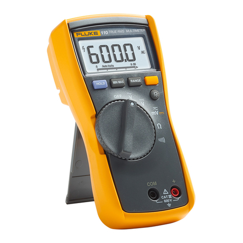
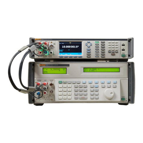
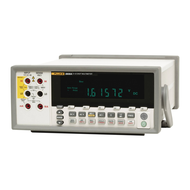
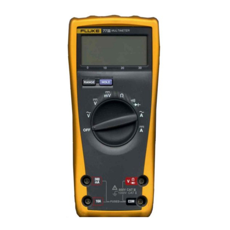
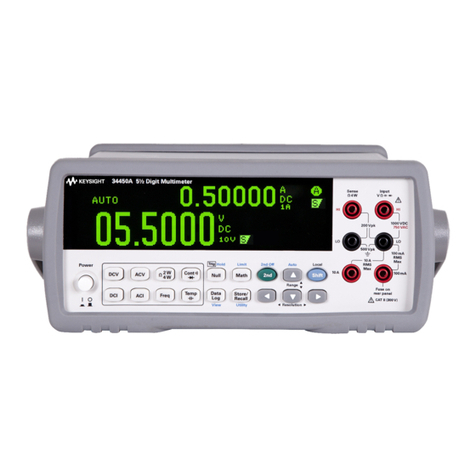
Fluke 8846A Operating and maintenance manual

®
8845A/8846A
Digital Multimeter
Programmers Manual
September 2006, Rev. 1, 11/07
© 2006, 2007 Fluke Corporation, All rights reserved.
All product names are trademarks of their respective companies.

LIMITED WARRANTY AND LIMITATION OF LIABILITY
Each Fluke product is warranted to be free from defects in material and workmanship under normal use and
service. The warranty period is one year and begins on the date of shipment. Parts, product repairs, and
services are warranted for 90 days. This warranty extends only to the original buyer or end-user customer of
a Fluke authorized reseller, and does not apply to fuses, disposable batteries, or to any product which, in
Fluke's opinion, has been misused, altered, neglected, contaminated, or damaged by accident or abnormal
conditions of operation or handling. Fluke warrants that software will operate substantially in accordance
with its functional specifications for 90 days and that it has been properly recorded on non-defective media.
Fluke does not warrant that software will be error free or operate without interruption.
Fluke authorized resellers shall extend this warranty on new and unused products to end-user customers
only but have no authority to extend a greater or different warranty on behalf of Fluke. Warranty support is
available only if product is purchased through a Fluke authorized sales outlet or Buyer has paid the
applicable international price. Fluke reserves the right to invoice Buyer for importation costs of
repair/replacement parts when product purchased in one country is submitted for repair in another country.
Fluke's warranty obligation is limited, at Fluke's option, to refund of the purchase price, free of charge repair,
or replacement of a defective product which is returned to a Fluke authorized service center within the
warranty period.
To obtain warranty service, contact your nearest Fluke authorized service center to obtain return
authorization information, then send the product to that service center, with a description of the difficulty,
postage and insurance prepaid (FOB Destination). Fluke assumes no risk for damage in transit. Following
warranty repair, the product will be returned to Buyer, transportation prepaid (FOB Destination). If Fluke
determines that failure was caused by neglect, misuse, contamination, alteration, accident, or abnormal
condition of operation or handling, including overvoltage failures caused by use outside the product’s
specified rating, or normal wear and tear of mechanical components, Fluke will provide an estimate of repair
costs and obtain authorization before commencing the work. Following repair, the product will be returned to
the Buyer transportation prepaid and the Buyer will be billed for the repair and return transportation charges
(FOB Shipping Point).
THIS WARRANTY IS BUYER'S SOLE AND EXCLUSIVE REMEDY AND IS IN LIEU OF ALL OTHER
WARRANTIES, EXPRESS OR IMPLIED, INCLUDING BUT NOT LIMITED TO ANY IMPLIED WARRANTY
OF MERCHANTABILITY OR FITNESS FOR A PARTICULAR PURPOSE. FLUKE SHALL NOT BE LIABLE
FOR ANY SPECIAL, INDIRECT, INCIDENTAL, OR CONSEQUENTIAL DAMAGES OR LOSSES,
INCLUDING LOSS OF DATA, ARISING FROM ANY CAUSE OR THEORY.
Since some countries or states do not allow limitation of the term of an implied warranty, or exclusion or
limitation of incidental or consequential damages, the limitations and exclusions of this warranty may not
apply to every buyer. If any provision of this Warranty is held invalid or unenforceable by a court or other
decision-maker of competent jurisdiction, such holding will not affect the validity or enforceability of any other
provision.
Fluke Corporation
P.O. Box 9090
Everett, WA 98206-9090
U.S.A.
Fluke Europe B.V.
P.O. Box 1186
5602 BD Eindhoven
The Netherlands
11/99
To register your product online, visit register.fluke.com

i
Table of Contents
Title Page
Introduction........................................................................................................ 1
Safety Information ............................................................................................. 1
Symbols ......................................................................................................... 2
Local and Remote Operation......................................................................... 2
Computer Interfaces ...................................................................................... 3
Optimizing System Speed for IO Operation...................................................... 3
Selecting the Remote Interface Port .................................................................. 4
Configuring the IEEE-448 Port ......................................................................... 4
IEEE 488 Operating Limitations ................................................................... 4
Setting the IEEE 488 (GPIB) Port Address................................................... 4
Capability Commands ................................................................................... 5
Interconnections ............................................................................................ 5
Configuring the RS-232 Port ............................................................................. 6
Setting RS-232 Baud Rate............................................................................. 6
Setting RS-232 Parity and Data Bits ............................................................. 7
Setting RS-232 Stop Bits............................................................................... 7
Setting RS-232 Flow Control ........................................................................ 7
Setting RS-232 End-Of-Line Character ........................................................ 7
Enabling and Disabling Fluke 45 Emulation Echo........................................ 7
RS-232 Modes of Operation.......................................................................... 8
Operating with FlukeView Forms’................................................................ 10
Interconnections ............................................................................................ 10
Configuring the Ethernet (LAN) Port ................................................................ 11
Setting the IP Address ................................................................................... 12
Setting the LAN Subnet Mask....................................................................... 13
Reading the Domain Name ........................................................................... 13
Configuring the Host Name........................................................................... 13
Reading the MAC Address............................................................................ 14
Configuring the LAN Default Gateway ........................................................ 14
Configuring the General Network Socket Port.............................................. 14
Establishing an Ethernet Connection................................................................. 15
Terminating an Ethernet Connection................................................................. 16
Selecting the Programming Language ............................................................... 16
Getting Started With an Installation Test........................................................... 16
Installation Test for RS-232 Connections ..................................................... 16

8845A/8846A
Programmers Manual
ii
Installation Test for IEEE 488 Connections .................................................. 17
If Test Fails.................................................................................................... 17
How the Meter Processes Input ......................................................................... 18
Input Strings .................................................................................................. 18
Input Terminators .......................................................................................... 18
Typical IEEE 488 Input Strings..................................................................... 19
Sending Numeric Values to the Meter .......................................................... 19
Sending Command Strings to the Meter........................................................ 19
How the Meter Processes Output....................................................................... 21
Triggering Input................................................................................................. 21
Internal Triggering......................................................................................... 21
External Triggering ....................................................................................... 22
Service Requests (IEEE 488 Only) and Status Registers .................................. 22
Standard Event Status and Standard Event Status Enable Registers............. 23
Questionable Data Event Register and Questionable Data Enable Register . 24
Status Byte Register ...................................................................................... 25
Reading the Status Byte Register .................................................................. 25
Service Request Enable Register................................................................... 26
Supported SCPI Commands .............................................................................. 27
SCPI Command Summary ............................................................................ 27
SCPI Command Details................................................................................. 36
Using the MEASure? Command ................................................................... 37
Using the CONFigure Command .................................................................. 38
Using the READ? Command ........................................................................ 41
Using the INITiate Command ....................................................................... 41
Using the FETCh? Command ....................................................................... 41
Using the SENSe Subsystem to Configure the Meter ................................... 41
Programming for Math Operations................................................................ 50
Programming the Trigger System.................................................................. 54
Using System-Related Commands ................................................................ 57
Using Status Reporting Commands............................................................... 60
Calibration Commands.................................................................................. 62
Using RS-232/Ethernet Interface Commands ............................................... 64
Command Terminators.................................................................................. 65
Alternate Programming Language Compatibility ......................................... 66
FLUKE 45 Command Emulation Summary...................................................... 67
Computer Interface Command Set ................................................................ 67
IEEE 488 Capabilities and Common Commands.......................................... 67
Triggering Output.......................................................................................... 74
Using FlukeView Forms.................................................................................... 75
Introduction........................................................................................................ 77
Introduction........................................................................................................ 85
Incompatible Fluke 45 Commands .................................................................... 85
Dual Functions............................................................................................... 86
Reading Rates................................................................................................ 86
Ranges ........................................................................................................... 86
Introduction........................................................................................................ 87
Your Meter and Your Network Administrator .................................................. 87
Network Primer.................................................................................................. 88
Physical Layer Wiring Schemes Supported by the Meter ............................. 88
Network Interconnection Devices ................................................................. 89
Basic Network Packet and Frame Contents .................................................. 89
IP Addresses and Segmented Networks ........................................................ 90
TCP/IP Protocol Stack................................................................................... 92

iii
List of Tables
Table Title Page
1. Safety and Electrical Symbols................................................................................ 2
2. IEEE-488 Compatibility Codes.............................................................................. 5
3. Factory Settings of RS-232 Communications Parameters ..................................... 6
4. Status Register Summary ....................................................................................... 22
5. Description of Bits in ESR and ESE ...................................................................... 24
6. Description of Bits in the Questionable Data Register........................................... 25
7. Description of Bits in the Status Byte Register...................................................... 26
8. CALibration command summary........................................................................... 27
9. CONFigure command summary ............................................................................ 28
10. IEEE-488.2 common command summary ............................................................. 28
11. Math command summary....................................................................................... 29
12. MEASure command summary ............................................................................... 29
13. Measurement configuration command summary ................................................... 30
14. RS-232 interface command summary .................................................................... 33
15. Status reporting command summary...................................................................... 34
16. System-Related command summary...................................................................... 35
17. Triggering command summary .............................................................................. 36
18. Preset Conditions for the MEASure? and CONFigure Commands ....................... 40
19. Allowed math/measurement function combinations.............................................. 50
20. IEEE Common Commands .................................................................................... 67
21. Fluke 45 Function Commands and Queries ........................................................... 69
22. Function Modifier Commands and Queries ........................................................... 70
23. Range and Measurement Rate Commands and Querie .......................................... 71
24. Measurement Queries............................................................................................. 72
25. Compare Commands and Queries.......................................................................... 73
26. Trigger Configuration Commands ......................................................................... 73
27. Miscellaneous Commands and Queries ................................................................. 74
28. Remote/Local Configuration Commands............................................................... 74
29. Trigger Types ......................................................................................................... 75
30. Execution Error Codes and Descriptions ............................................................... 77
31. Ethernet/GPIB Configuration Errors...................................................................... 81
32. Calibration Errors................................................................................................... 82
33. Non-compatible Fluke 45 Remote Commands ...................................................... 85
34. Fluke 45 Dual Function Compatibility Matrix....................................................... 86
35. IP Address Assignments ........................................................................................ 91

8845A/8846A
Programmers Manual
iv

v
List of Figures
Figure Title Page
1. RS-232 Pin-out and Cable Interconnect................................................................. 11
2. Typical IEEE-488 Input String .............................................................................. 20
3. Overview of Status Data Structure......................................................................... 23
4. 884XA Triggering System ..................................................................................... 55

8845A/8846A
Programmers Manual
vi

1
Remote Operation
Introduction
Remote operation of the 8845A or 8846A Digital Multimeters (hereafter “the Meter”)
from a host, that is, a terminal, controller, PC, or computer, is accomplished by sending
commands to it through one of its remote interfaces. This manual describes how to setup,
configure, and operate the Meter through each of the remote interfaces.
The Meter is controlled remotely using either Standard Commands for Programmable
Instruments (SCPI) or Fluke 45 commands. Detailed information on the SCPI command
set, and how the Meter processes those commands is included in this manual. Fluke 45
command limitations are covered in Appendix B in this manual.
Note
For more information regarding the SCPI programming language, visit
http://www.scpiconsortium.org. A free copy of the SCPI standard can be
found at http://www.scpiconsortium.org/SCPI-99.pdf.
The level of detail in this chapter is based on the assumption that the reader is familiar
with the basics of data communication interface, and the IEEE 488 bus.
Safety Information
This section addresses safety considerations and describes symbols that may appear on
the Meter or in the manual.
A XW Warning statement identifies conditions or practices that could result in injury
or death.

8845A/8846A
Programmers Manual
2
A WCaution statement identifies conditions or practices that could result in damage to
the Meter or equipment to which it is connected.
XW Warning
To avoid electric shock, personal injury, or death, carefully read
the information under “Safety Information” before attempting to
install, use, or service the Meter.
Symbols
Table 1 is a list of safety and electrical symbols that appear on the Meter or in this
manual.
Table 1. Safety and Electrical Symbols
Symbol Description Symbol Description
WRisk of danger. Important
information. See manual ODisplay ON / OFF
XHazardous voltage. Voltage > 30 V
dc or ac peak might be present JEarth ground
BAC (Alternating Current) ECapacitance
FDC (Direct Current) GDiode
IFuse
D
or
C
AC or DC (Alternating or Direct
Current) YDigital signal
RContinuity test or continuity beeper
tone UMaintenance or Service
YPotentially hazardous voltage CAT II IEC 61010 Overvoltage (installation or
measurement) Category 2.
TDouble insulated <Recycle
hStatic awareness. Static discharge
can damage part(s) ~Do not dispose of this product as unsorted
municipal waste. Go to Fluke’s website for
recycle information.
Local and Remote Operation
When the Meter is operated from a host, it is said to be operated remotely. When operated
from the front panel, it is said to be operated locally.
Most operations that can be performed locally can also be performed remotely over the
remote interface. Some operations, like setting communications parameters for the
RS-232 interface, and addressing the Meter for IEEE 488 operations can only be set
through the front panel.
XW Warning
To avoid electric shock, turn off the signal source to the Meter
before touching the test leads. The front panel display may not
indicate the true input voltage while in remote mode. Always
assume lethal voltages exist on the front-panel inputs.

Digital Multimeter
Optimizing System Speed for IO Operation
3
Computer Interfaces
Both the 8845A and 8846A Multimeters come equipped with an RS-232, Ethernet, and
IEEE 488 interface. Only one remote interface can be enabled at a time. Using any of the
interfaces turns the Meter into a fully programmable instrument that can be integrated
into an automated instrumentation system. For a PC with only USB ports, Fluke makes a
cable (Fluke PN 2675479) that converts between USB and RS-232 ports.
Note
The remote interface port and settings can be changed only through the
Meter’s front-panel controls.
Enabling or selecting a port for remote operation is a separate process from setting the
various parameters associated with a remote interface. An interface does not have to be
selected to set its parameters; the baud rate of the RS-232 port can be set while the Meter
has the LAN port enable, as the remote control port.
Optimizing System Speed for IO Operation
Several factors affect the remote system speed of the 8845A/46A. To make the fastest
measurements, it is best to store the measurements in internal memory before transferring
across the IO bus. This is particularly true if you want to collect a large number of
samples per measurement. Set up all of the parameters (i.e. function, range, filters, etc...)
prior to the measurements. Use the internal trigger. Set the trigger delay to zero. Turn off
the display. If operating with RS232, use the fastest baud rate available. The commands
that will run the fastest are the "INIT" and "FETCH?" combination.
One example of taking the fastest voltage readings is:
*cls # This clears all error prior to initiating readings
conf:volt:dc 0.1 # Set the DC range to manual and 100 mV.
volt:dc:nplc 0.02 # Set the NPLC to faster reading rate 4 1/2 digits.
zero:auto 0 # Turn Autozero off.
trig:sour imm # Set immediate trigger.
trig:del 0 # Set trigger delay to zero.
trig:coun 1 # Set trigger count to one or specify a larger number.
disp off # Turn display off. This may slightly improve reading rate.
syst:rem # Put the 8846 in remote. Only needed for RS-232 or Ethernet
#(required for READ?)
samp:coun 100 # Set the sample count from 1 to 5000.
:INIT; *OPC? # "*OPC?" returns 1 indicating that the measurements have been
taken and are ready to be transferred to the computer using the
FETCH? command.
:FETCH?
Note
For any sample count greater than 1, measurements are returned comma
separated.

8845A/8846A
Programmers Manual
4
Selecting the Remote Interface Port
To enable or select a port for remote control of the Meter:
1. Press I.
2. Press PORT IF.
3. Press SELECT PORT.
4. Press the soft key labeled with the desired port: RS-232C, IEEE488, or LAN.
Port selection is non-volatile. Therefore, the selected port will remain active until another
port is selected through the front panel.
Configuring the IEEE-448 Port
The IEEE 488 interface is designed in compliance with supplemental standard IEEE
488.2. Devices connected to the bus in a system are designated as talkers, listeners,
talker/listeners, or controllers. The connector for connecting the Meter to the IEEE 488
bus is located on the rear panel. Under control of an instrument controller, the Meter
operates exclusively as a talker/listener on the IEEE 488 bus.
The Meter conforms to the Standard Specification IEEE 488.1 – 1987: IEEE Standard
Digital Interface for Programmable Instrumentation, and to IEEE 488.2 - 2004: Codes,
Formats, Protocols, and Common Commands.
IEEE 488 Operating Limitations
The following limitations govern the IEEE 488 remote interface:
•A maximum of 15 instruments may be connected in a single IEEE 448 bus system.
•The maximum length of IEEE 488 cable used on a single IEEE 488 system must be the
lesser of 20 meters, or 2 meters times the number of devices in the system.
Setting the IEEE 488 (GPIB) Port Address
Before the Meter will accept commands through the IEEE 488 remote interface, IEEE
488 must first be enabled or selected as the active interface port. This can only be done
through the Meter’s front panel.
A controller uses an address between 1 and 32 to identify a specific instrument on the
bus. The Meter is shipped from the factory with the IEEE 488 port address set to 1. To
change the IEEE 488 address:
1. Press I.
2. Press PORT IF.
3. Press IEEE488.
4. Use the soft keys to set the address as follows.
Select the address digit to adjust by pressing either <-- or -->.
With the desired digit selected, press the soft key labeled -- to decrement the digit
or ++ to increment the character.
5. With the desired address set, press ENTER.

Digital Multimeter
Configuring the IEEE-448 Port
5
Capability Commands
To conform to the IEEE 488.1 standard specification, it is not essential for a device to
encompass the full range of bus capabilities. The IEEE 488.1 document describes and
codes the standard bus features, so that manufacturers may give brief coded descriptions
of their own interfaces’ overall capability.
The codes that apply to the Meter are given in Table 1 below, together with short
descriptions. These codes conform to IEEE 488.2 requirements.
Appendix C of the IEEE 488.1 document contains a complete description of each code.
Table 2. IEEE 488 Compatibility Codes
IEEE 488 Subset Interface Functions
SH1 Source Handshake Capability
AH1 Acceptor Handshake Capability
T5 Talker (basic talker, serial poll, unaddressed to talk if addressed to listen)
L4 Listener (basic listener, unaddressed to listen if addressed to talk)
SR1 Service Request Capability
RL1 Remote/Local Capability (includes local lockout)
PP0 No Parallel Poll Capability
DC1 Device Clear Capability
DT1 Device Trigger – Supports group trigger (GET).
C0 No Controller Capability
E2 Open-Collector and Three-State Drivers
Interconnections
Instruments fitted with an IEEE 488 interface communicate with each other through a
standard set of interconnecting cables, as specified in the IEEE 488.1 Standard
document.
The IEEE 488 interface connector is located on the Meter’s rear panel.

8845A/8846A
Programmers Manual
6
Configuring the RS-232 Port
The RS-232 Communication Interface allows ASCII, asynchronous, serial
communication between the Meter and a host or terminal. The following sections
describe the process of configuring the RS-232 port. To make the RS-232 port the active
port for remote operation, see the “Selecting the Remote Interface Port” section above.
Table 3 lists the RS-232 parameter settings when the Meter leaves the factory.
Table 3. Factory Settings of RS-232 Communications Parameters
Parameter Factory Setting
Baud Rate 9600
Parity None (Parity bit 0)
Number of Data Bits 8 (7 data bits plus 1 parity bit)
Number of Stop Bits 1
Flow Control None
To access the RS-232 setup menu:
1. Press I.
2. Press the PORT IF soft key.
3. Press the RS232 soft key.
At this point, all the RS-232 settings are made available.
Note
All RS-232 port parameter settings are non-volatile and remain set until
changed.
Setting RS-232 Baud Rate
To set the baud rate:
1. With the RS-232 set up menu displayed, press BAUD RATE.
There are eight pre-defined settings: 1200, 2400, 4800, 9600, 19200 38400, 57600,
115200, and 230400. These selections are displayed in two separate menus. When
first entering baud rate selection, baud rates 9600 to 1200 are displayed. To get to the
next five higher baud rates, press MORE. To get back to the lower baud rates, press
B.
2. With the desired baud rate displayed, press the soft key under the chosen baud rate.

Digital Multimeter
Configuring the RS-232 Port
7
Setting RS-232 Parity and Data Bits
To set the data bits:
1. With the RS-232 set up menu displayed, press PARITY DATA BIT.
2. Press the soft key under the desired parity, and data bit parameter.
NONE 8B DATA = No parity with 8 data bits
ODD 7B DATA = Odd parity with 7 data bits
EVEN 7B DATA = Even parity with 7 data bits
Setting RS-232 Stop Bits
To set the stop bits:
1. With the RS-232 set up menu displayed, press PARITY DATA BIT.
2. Press the soft key labeled 2STOP BITS to toggle between 1 and 2 stop bits.
Note
When 2 STOP BITS is highlighted, the interface is configured to use 2 stop
bits.
Setting RS-232 Flow Control
To set flow control:
1. With the RS-232 set up menu displayed, press FLOW CONTROL.
2. Press the soft key under the desired flow control.
NONE = No flow control
XON = Software flow control Xon (hex 11) and Xoff (hex 13)
RTS = Hardware flow control, RTS/DTS
Setting RS-232 End-Of-Line Character
To set the End-Of-Line (EOL) character:
1. With the RS-232 set up menu displayed, press EOL.
2. Press the soft key labeled with the desired End-Of-Line character(s).
CR = Carriage return only
LF = Line Feed only
CR LF = Carriage Return and Line Feed
Enabling and Disabling Fluke 45 Emulation Echo
Although you can turn echo on or off at anytime, the selection is used only when the
Meter’s command mode is set to Fluke 45 emulation.
To enable or disable Echo for the RS-232 port:
1. With the RS-232 set up menu displayed, press COMP/TERM ECHO.
2. Press either the ECHO or NO ECHO soft key.

8845A/8846A
Programmers Manual
8
RS-232 Modes of Operation
RS-232 communication is slightly different between the 884X and Fluke 45 emulation
modes. Switching between these two commands sets is covered in the “Selecting the
Programming Language” section later in this manual. The following sections explain the
differences in communications protocol and how to set the Meter and computer
parameters for proper operation.
884X Mode
There are two modes of RS-232 operation when the Meter has the 884X command set
selected: TERMINAL and COMPUTER. The terminal mode is an interactive mode
where an operator inputs commands, with immediate returns for requested information
(queries) and interface messages. In terminal mode, characters sent to the Meter are
echoed on the host’s display screen and a command prompt (for example 3>) is returned
after the CR/LF is entered by the terminal. If you send a character to the Meter over the
RS-232 interface, pressing the <DELETE> or <BACKSPACE> key deletes the previous
character. A backspace is echoed to the host terminal.
Note
^C (CNTRL C) is the RS-232 equivalent of IEEE 488 DCI (device clear),
causing “1>” followed by a carriage return and line feed to be output.
The computer mode is used when the Meter is operated by computer program. In this
mode, requested information is returned by query, and interface messages are queued and
returned by command. Characters are not echoed on the host computer and command
prompts are suppressed. The <DELETE> or <BACKSPACE> keys are ignored.
Selecting Between Computer and Terminal Mode
Although you can select between Computer and Terminal mode at any time, the selection
is used only when the Meter’s command mode is set to 884X.
To select computer or terminal mode from the front panel:
1. Press Iand then PORT IF.
Note
If the RS232 port is not already highlighted, press SELECT PORT and
then RS232.
2. Press either RS232, COMP/TERM ECHO and select either COMPUTER or
TERMINAL.
Fluke 45 Mode
In the Fluke 45 Command emulation mode, there are two modes of RS-232 operation:
ECHO or NO ECHO. In Echo mode, characters sent to the Meter are echoed on the
host’s display screen. In No Echo mode, characters sent are not echoed.
To set the echo parameter, refer to the "Enabling and Disabling RS-232 Echo" section
earlier in this manual. If you send a character to the Meter over the RS-232 interface,
pressing the <DELETE> or <BACKSPACE> key deletes the previous character. A
backspace is echoed to the display screen if Echo On mode is set.
In either mode, when the host sends a command to the Meter over the RS-232 interface,
the Meter parses and executes the command, and returns a response if appropriate, and
sends one of three prompts:

Digital Multimeter
Configuring the RS-232 Port
9
=> No errors were detected and the command was successfully parsed and
executed.
?> A Command Error was detected. The command was not executed because it
was not understood. For instance, this prompt would be returned if the Meter
was sent an input string that contained a syntax error.
!> An Execution Error was detected. The command was understood but not
executed (i.e., a device-dependent error). For instance, this prompt would be
returned if you attempted to use the decibels modifier (dB) on a frequency
measurement (FREQ).
Note
^C (CNTRL C) is the RS-232 equivalent of IEEE-488 DCI (device clear),
causing "=>" followed by a carriage return and line feed to be output.
Terminations for the end of line can be set to carriage return (CR), line feed (LF), or both
(CRLF). Terminations for the end of line can be set in the <Instr SETUP><PORT
IF><RS232C> selection.
To change the Meter into Fluke 45 Emulation Mode, setup the remote interface for
RS232 or IEEE488 (Fluke 45 mode will not work over Ethernet):
For RS232
1. Press I
2. Press PORT IF softkey.
3. Press the SELECT PORT softkey.
4. Press the RS-232 softkey.
Set the baud rate to 9600 as follows:
1. Press I
2. Press PORT IF softkey.
3. Press the RS-232 softkey.
4. Press the BAUD RATE softkey.
5. Press the 9600 softkey.
Set the RS232 port to non-echo as follows:
1. Press I
2. Press PORT IF softkey.
3. Press the RS-232 softkey.
4. Press the COMP/TERM ECHO
5. Press the NO ECHO softkey.
For IEEE488
1. Press I
2. Press PORT IF softkey.
3. Press the SELECT PORT softkey.
4. Press the IEEE-488 softkey.
Set the IEEE488 address to a system compatible value as follows:

8845A/8846A
Programmers Manual
10
1. Press I
2. Press PORT IF softkey.
3. Press the IEEE-488 softkey.
4. Use the soft keys to set the address as follows.
Select the address digit to adjust by pressing either <-- or -->.
With the desired digit selected, press the soft key labeled -- to decrement the digit
or ++ to increment the character.
5. With the desired address set, press ENTER.
To set the Meter to Fluke 45 emulation:
1. Press I
2. Press the COMMANDS softkey.
3. Press the Fluke 45 softkey.
Operating with FlukeView Forms’
When first powered up, FlukeView Forms sends remote commands to the serial port
asking an instrument to identify itself. Because the Meter does not recognize the
commands for the other instruments, an error indication (Syntax error [-102]) is shown on
the Meter’s front panel. This is considered normal operation. See FlukeView Forms
documentation for information on setting up that application. When controlling the Meter
with FlukeView Forms, ECHO must be set to NO ECHO.
Interconnections
The Meter communicates with a host through a DB-9 interface connector on the rear
panel of the Meter. Connect the Meter to the host or terminal using a cable appropriate to
your application that is less than 50 feet (15 meters) long. Longer cables are permitted,
providing that the load capacitance measured at the interface point (including the signal
terminator) does not exceed 2500 picofarads.
Figure 1 shows the pin-out of the Meter’s RS-232 port, and two possible cable
connections for communicating with a PC.

Digital Multimeter
Configuring the Ethernet (LAN) Port
11
Not Used
RxData
TxData
Not Used
GND
Not Used
RTS
CTS
Not Used
Not Used
RxData
TxData
Not Used
GND
Not Used
RTS
CTS
Not Used
Keys
DCD
RxData
TxData
DTR
GND
-
-
-
-
-
Data Carrier Detect
Receive Data
Transmit Data
Data Terminal Ready
Circuit Ground
DSR
RTS
CTS
RI
-
-
-
-
Data Set Ready
Request to Send
Clear to Send
Ring Indicator
DCD
RxData
TxData
DTR
GND
DSR
RTS
CTS
RI
DCD
RxData
TxData
DTR
GND
DSR
RTS
CTS
RI
No Connect
RxData
TxData
DTR
GND
DSR
RTS
CTS
No Connect
No Connect
RxData
TxData
DTR
GND
DSR
RTS
CTS
No Connect
1
2
3
4
5
6
7
8
9
1
2
3
4
5
6
7
8
9
1
2
3
4
5
6
7
8
9
1
2
3
4
5
6
7
8
9
1
2
3
4
5
6
7
8
9
1
2
3
4
5
6
7
8
9
8845/46 Cable (Null Modem such as Fluke RS43) PC
8845/46 Cable (USB to RS232 such as Fluke 884X-USB) PC
USB
Interface
USB
Adapter
caw058.eps
Figure 1. RS-232 Pin-out and Cable Interconnect
Configuring the Ethernet (LAN) Port
The Meter can be remotely controlled through the LAN port on the Meter’s rear panel.
To select the LAN port as the remote control port, see the “Selecting the Remote
Interface” above.
Configuring the LAN port is accomplished through the Instrument Setup function. The
selectable LAN port parameters are: DHCP (Dynamic Host Configuration Protocol), IP
Address, Net mask, Host Name, Mac Address, Gateway, Port number, and Domain.

8845A/8846A
Programmers Manual
12
When setting IP addresses, subnet masks, and default gateways on the Meter, keep in
mind they are stored as 32-bit binary numbers and expressed as four 3-digit segments in
dot-notation form. For example, xxx.xxx.xxx.xxx where xxx is a byte value.
To set the LAN port parameters:
1. Press I.
2. Press the PORT IF soft key.
3. Press the LAN soft key.
Note
When addressing some LAN addresses, computers will often interpret 0's in
the IP address as OCTAL values. As an example, if you configure your IP
address from the front panel as 129.196.017.023 and then attempt to
establish a connection to the meter, you should connect using the IP
address 129.196.17.23. Attempting to establish a connection to
129.196.017.023 may result in a connection request to 129.196.15.19.
Setting the IP Address
An internet (IP) address is required for all internet and TCP/IP communications. If DHCP
is enabled, the Meter will use the dynamic address supplied by the DHCP server.
However, if the DHCP server fails to supply the address, or DHCP is disabled, the
currently configured static IP address will be used.
Selecting Dynamic Host Configuration Protocol (DHCP)
Dynamic Host Configuration Protocol (DHCP) is a client-server protocol that eliminates
having to manually set permanent/static IP addresses. The DHCP server provides
configuration parameters (dynamic IP address, subnet mask, and default gateway IP
addresses) which are required for a client host to participate in an IP network.
Using DHCP is the easiest way to configure the Meter for remote communication
through the LAN interface. DHCP is enabled when the Meter is shipped from the factory.
When connected to a network, and the LAN port enabled, the Meter will try and retrieve
the parameters from a DHCP server necessary for communications. If the parameters
can’t be obtained, the Meter switches to the parameters that were manually entered into
the Meter.
To disable or enable DHCP on the Meter:
From the PORT IF menu, press LAN. If DHCP is already enabled, then DHCP will
be highlighted in the display. Pressing DHCP will toggle between enabled and disabled.
Note
After changing any Ehternet setting, the Meter must be powered off and on
again to make the change active.
Setting a Static Internet Address
The Meter comes from the factory with 000.000.000.000 in the static IP address register.
Note
If you are planning to use the Meter on a corporate LAN and do not wish to
use DHCP, contact your network administrator for a static IP address to be
used exclusively in your Meter. DHCP must be disabled to set a static IP
address.
This manual suits for next models
3
Table of contents
Other Fluke Multimeter manuals

Fluke
Fluke 8050A User manual

Fluke
Fluke Biomedical MPS450 Operators User manual

Fluke
Fluke CNX C3001 User manual

Fluke
Fluke 287C Use and care manual

Fluke
Fluke 8502A User manual

Fluke
Fluke 8050A User manual

Fluke
Fluke 8588A User manual

Fluke
Fluke LinkRunner Duo User manual

Fluke
Fluke 1587 Use and care manual

Fluke
Fluke 8845A Operating and maintenance manual

Fluke
Fluke 8050? User manual

Fluke
Fluke 175 User manual

Fluke
Fluke 77 Series IV User manual

Fluke
Fluke 187 Use and care manual

Fluke
Fluke 8030A User manual

Fluke
Fluke Series II User manual

Fluke
Fluke 8508A User manual

Fluke
Fluke 233 User manual

Fluke
Fluke LinkRunner Pro User manual

Fluke
Fluke 8508A User manual