AMQ Solutions ILINE Operating and maintenance instructions

ILINE power/data beam
Installation Guide

180o(2-Way) ILINE Post Assembly
Components .................................................... 4
Post, Beam Plate, and Feet Assembly.......... 5-9
120o(3-Way) ILINE Post Assembly
Components .................................................. 11
Post and Beam Assembly......................... 12-13
Entering Electric Base Feed........................... 14
Cover and Trim Assembly .............................. 15
Extending the Configuration........................... 16
90o/180o(4-Way) ILINE Post Assembly
Components .................................................. 18
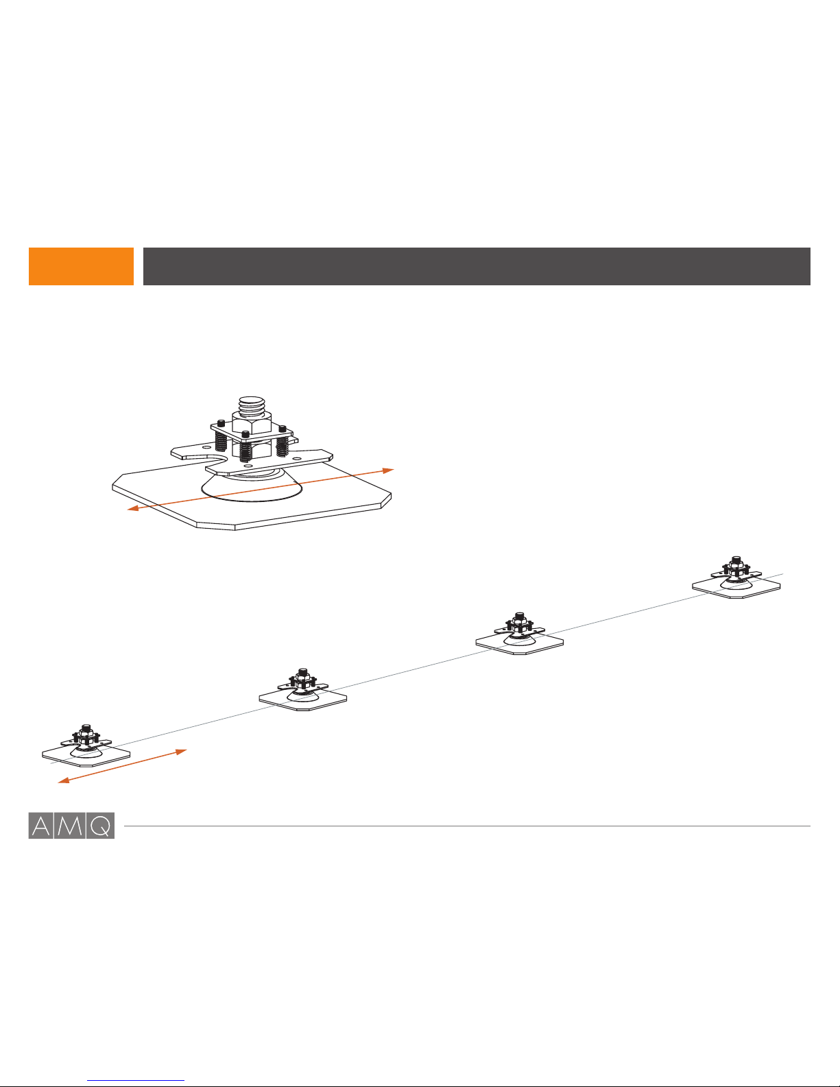
Foot and Base Plate Assembly................. 19-20
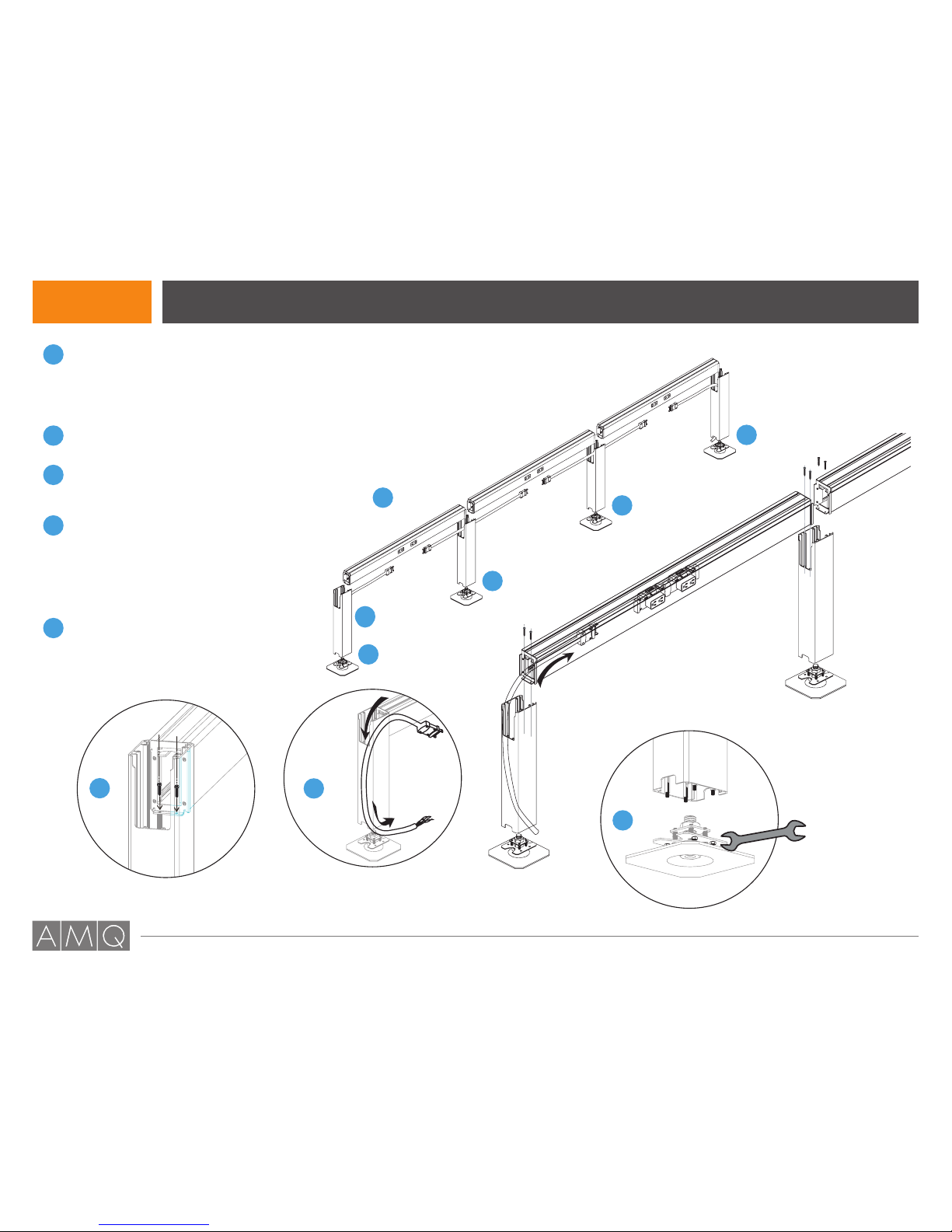
Beam Assembly ........................................ 21-22
Post, Beam and Base Feed ........................... 23
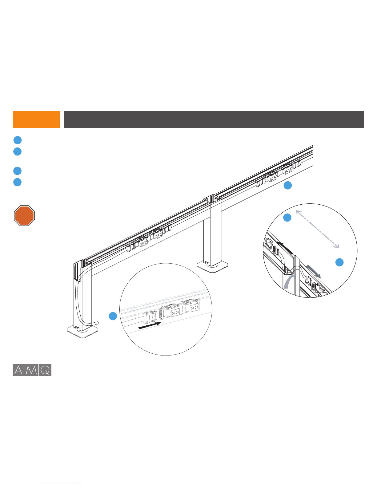
Jumpers ......................................................... 24
Caps and Covers ........................................... 25
Post Sleeve..................................................... 26
Screens .......................................................... 27
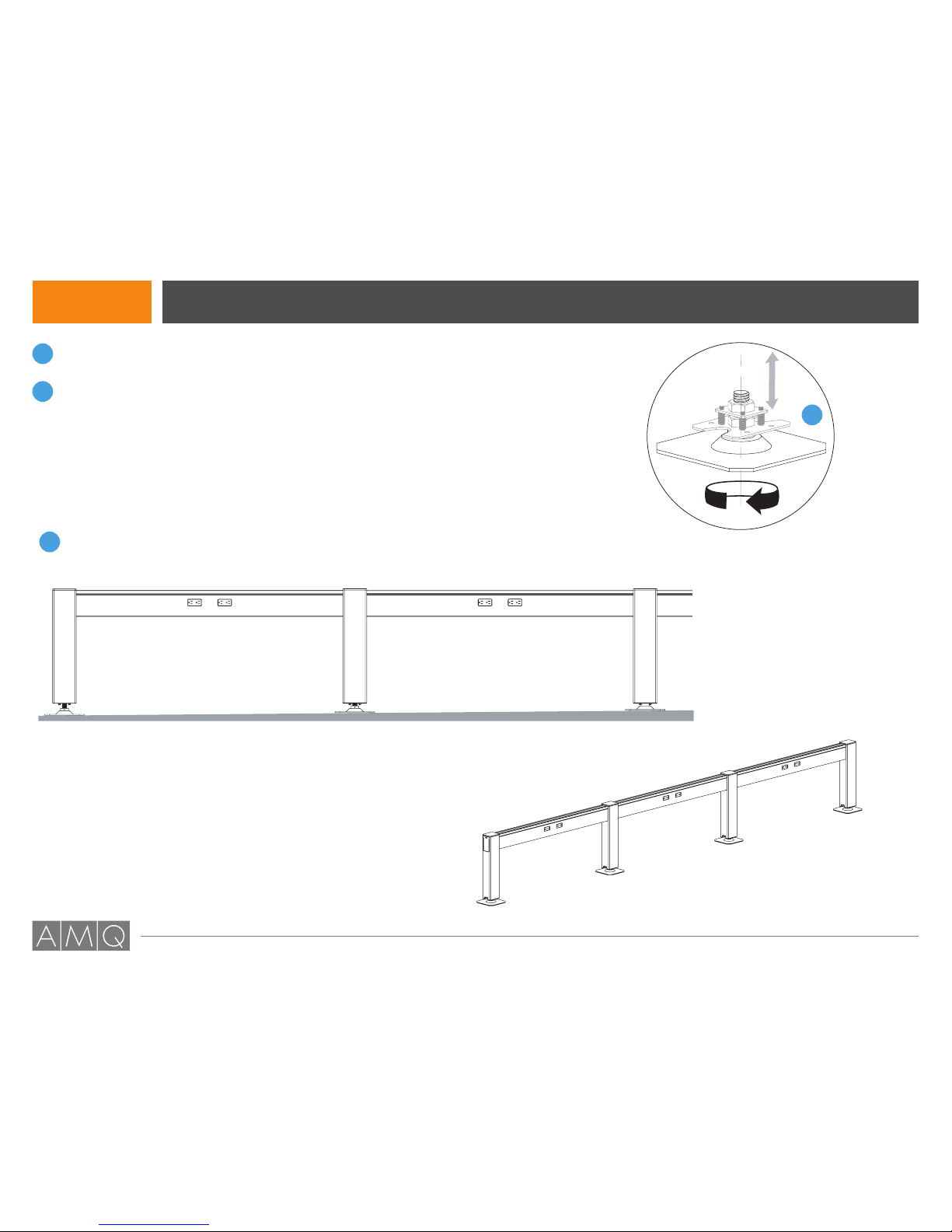
Final Adjustments........................................... 28
Power Pole Retrofit ......................................... 29
ILINE Beam System Installation
Index
2
Please contact [email protected] if you are missing any parts, have difficulty with assembly, or have any product related questions.

ILINE installation guide 180° (2-WAY)

180° Post is for inline/2-way applications only.
Components
iLine 180 Post x 1
Nuts x 4
Feet Assembly x 1
Side Plastic Cover x 1
Top Cap x 1
ILINE 180o(2-Way) Post Installation Guide
4
Please contact [email protected] if you are missing any parts, have difficulty with assembly, or have any product related questions.

Phase 1 Post, Beam Plate and Feet Assembly ILINE 180o(2-Way) Post Installation Guide
For receptacle installation, see pages 21-22.
6
6
Place each foot assembly down based on
the pre-established design configuration.
*PLATE DIRECTION:
When setting the plates
down, make sure the open
cutouts of the plates and
cutouts of the posts are
aligned and facing in the
same direction as the spine.
*
5
Please contact [email protected] if you are missing any parts, have difficulty with assembly, or have any product related questions.

Phase 2 Post, Beam Plate and Feet Assembly
5
4
3
1
5
2
3
4
Once complete, lay each beam assembly
between each foot assembly.
NOTE: Make sure the Outer-to-Inner
beams are mounted to the ends while the
Inner-to-Inner beams go in between them.
Place (do not fasten) the vertical posts on
each of the footer assemblies.
Slide the beam assemblies onto each of
the vertical posts and fasten each side of
the beam using 2 screws.
Take the exposed end of the power entry
and feed through the desired end of the
beam and into the adjacent post-opening.
Continue to feed the power entry until
the exposed end is out through one of
the base plate’s openings.
Secure the post to the footer assembly
using a 7/16” spanner.
4
2
4
4
4
are slightly longer than
Outer-to-Inner
Beam Outer-to-Inner
Beam
Inner-to-Inner
Beam
NOTE:
Inner-to-Inner beams
Outer-to-Inner beams.
NOTE:
L-shaped configurations
must use inner-to-inner beam
1
* Use phillip head screw to mount
beams on vertical posts.
ILINE 180o(2-Way) Post Installation Guide
6
Please contact [email protected] if you are missing any parts, have difficulty with assembly, or have any product related questions.

Phase 3 Post, Beam Plate and Feet Assembly
1
2
3
1
2
2
Connect power entry plug to the junction block.
Feed the jumper through the beam canal and
into the vertical post opening into the next beam
assembly.
Connect the jumper to each junction block.
Repeat Steps 1-3 until the last jumper is
connected the last junction block.
The remaining installation of electrical must
be installed by a professional electrician.
STOP
3
4
ILINE 180o(2-Way) Post Installation Guide
7
Please contact [email protected] if you are missing any parts, have difficulty with assembly, or have any product related questions.

Phase 4 Post, Beam Plate and Feet Assembly
1
1
24
3
2
3
Insert side covers into all exposed openings of
each vertical posts.
Place top caps on all vertical posts.
Take two data adapters/face plates and snap
them onto each end of the underside of the beam
assembly. Snap on data face plates.
Insert the bottom beam plates between each data
adapter on the underside of the beam assembly.
Repeat Steps 1-4 for all beam assemblies.
4
5
ILINE 180o(2-Way) Post Installation Guide
8
Please contact [email protected] if you are missing any parts, have difficulty with assembly, or have any product related questions.

Phase 5 Post, Beam Plate and Feet Assembly
1
2
Check the horizontal alignment
of the beams .
If not aligned, please rotate the
foot to adjust each post’s
elevation until leveled.
NOTE: Use a leveling guide for accuracy.
You may adjust height of each post by
rotating the base plates in order to
level all horizontal beams.
*
2
Completed ILINE
1
ILINE 180o(2-Way) Post Installation Guide
9
Please contact [email protected] if you are missing any parts, have difficulty with assembly, or have any product related questions.

ILINE installation guide 120° (3-WAY)

ILINE 120° (3-Way) Post Installation Guide
Components
Top cap
120degree
vertical post
Base plate
Glide, OEM
Post Side Cover
Hex Nuts
11
Please contact [email protected] if you are missing any parts, have difficulty with assembly, or have any product related questions.

Phase 1 Post and Beam Assembly ILINE 120° (3-Way) Post Installation Guide
1Refer to Phases 1 and 2 on pages 4-7.
For receptacle installation, see pages 21-22.
12
Please contact [email protected] if you are missing any parts, have difficulty with assembly, or have any product related questions.

Phase 2 Post and Beam Assembly
1
2
2
3
1
3
Assemble the base plate, glide and post together.
Slide the beam assembly into the open slots in the center of vertical post.
Fasten the beams using two screws on each end.
Use 1/4”-20 hex nut to tight down
posts on the footer-assemblies
7/16” Spanner
ILINE 120° (3-Way) Post Installation Guide
13
Please contact [email protected] if you are missing any parts, have difficulty with assembly, or have any product related questions.

Phase 3 Entering Electric Base Feed
1
2
Take the exposed end of the power entry and feed through the center vertical post.
Plug the power entry plug to the junction block.
NOTE: Depending on the floor plan, you may access the base feed
through any of the posts in the assembly.
1
2
ILINE 120° (3-Way) Post Installation Guide
14
Please contact [email protected] if you are missing any parts, have difficulty with assembly, or have any product related questions.

Phase 4 Cover and Trim Assembly
1
2
3
4
Insert side covers into each exposed opening in vertical posts.
Attach top cover to the center vertical post.
Snap on data face plates onto each end of the beam assemblies.
Insert the bottom beam plate between each data adapter on the
underside of the beam assembly.
1
2
4
3
ILINE 120° (3-Way) Post Installation Guide
15
Please contact [email protected] if you are missing any parts, have difficulty with assembly, or have any product related questions.

Phase 5 Extending the Configuration
1
2
3
4
Selecting the post that will accommodate the extension,
replace the end foot plate (DRE) with a center foot.
Open the top cap, then insert the new beam assembly.
Feed the jumper through the beam canal and into the
vertical post opening into the next beam assembly.
Connect the jumper to each junction block.
Re-attach the top cover onto the vertical post.
1
4
2
3
ILINE 120° (3-Way) Post Installation Guide
DRE
DRC
16
Please contact [email protected] if you are missing any parts, have difficulty with assembly, or have any product related questions.

ILINE installation guide 90°/180° (4-WAY)

Fabric Screen Screen Clips
Horizontal Beam
Data Adaptor Recpetacle
Cover
Junction Bracket
(3 circuit sys.)
Junction Bracket
(4 circuit sys.)
OR
Bottom Beam Plate
Wire Tray
Top Cap
Vertical Post
Post Side Covers
Hex Nuts
Base Plate Kit
Foot SRE
Foot SRC
Foot DRE
Foot DRC
Post Sleeve
Data Face Plate
Components ILINE 90°/180° (4-Way) Post Installation Guide
18
Please contact [email protected] if you are missing any parts, have difficulty with assembly, or have any product related questions.

Phase 1 Foot and Base Plate Assembly ILINE 90°/180° (4-Way) Post Installation Guide
1
2
3
4
1
2
Insert a 3” bolt into each of the 2” compression springs.
Insert the bolts and the compression springs into the
inner corner holes of the base plate.
Screw the bolts into the coupling nuts until the bolt tips are revealed.
Screw the foot assembly to the foot plate nuts.
Repeat Steps 1-4 for the all foot and base plates.
3
4
5- 4” x 3” Bolt (5/16” x 18)
- 4” x 2” Compression Spring
- Base Plate
- 4” x 3/4” Coupling Nut (5/16” x 18)
- Foot Plate Nut
- Foot Plate
19
Please contact [email protected] if you are missing any parts, have difficulty with assembly, or have any product related questions.

Phase 1 Foot and Base Plate Assembly ILINE 90°/180° (4-Way) Post Installation Guide
Completed Foot Plate
6
6
Place each foot assembly down based on
the pre-established design configuration.
*PLATE DIRECTION:
When setting the plates
down, make sure the open
cutouts of the plates and
cutouts of the posts are
aligned and facing in the
same direction as the spine.
*
20
Please contact [email protected] if you are missing any parts, have difficulty with assembly, or have any product related questions.
Table of contents
Other AMQ Solutions Indoor Furnishing manuals
Popular Indoor Furnishing manuals by other brands

AMF
AMF 805 installation guide

Teknion
Teknion Marini Adjustment features & instructions

Inside Weather
Inside Weather ARCADIA LOUNGE CHAIR manual

VAS
VAS XL50-5GB Assembly manual

Sisters Log Furniture & Home Decor
Sisters Log Furniture & Home Decor Deck Bench Assembly instructions

Flash Furniture
Flash Furniture HLC-1388 instruction manual

Forte
Forte Regal HEYR711 Assembling Instruction

ZEITRAUM
ZEITRAUM CURTAIN COUCH Assembly instructions

Cooper Lighting
Cooper Lighting HALO H1DRPLRG specification

Pawleys Island
Pawleys Island Durawood Assembly instructions

Crate&Barrel
Crate&Barrel Lafayette Assembly instructions

RSA Lighting
RSA Lighting QCT1775 specification