Amsco RELIANCE 444 User manual

UNCRATING/INSTALLATION INSTRUCTIONS
AMSCO® RELIANCE® 444
Load/Unload Modules
(07/15/99) P-122994-142
Rev. 6

LIMITATIONS OF LIABILITY AND INDEMNITY
IN NO CASE, WHETHER AS A RESULT OF A BREACH OF CONTRACT, BREACH OF WAR-
RANTY OR TORT (INCLUDING STERIS'S OR CUSTOMER'S WILLFUL ACTS OR NEGLIGENCE
OR STRICT LIABILITY) SHALL STERIS OR CUSTOMER BE LIABLE TO THE OTHER FOR ANY
CONSEQUENTIAL OR INCIDENTAL DAMAGES INCURRED BY THE OTHER, INCLUDING, BUT
NOT LIMITED TO, LOSS OF REVENUE, PROFITS OR GOODWILL. HOWEVER, NOTHING
CONTAINED IN THIS AGREEMENT IS INTENDED TO RELIEVE EITHER STERIS OR CUS-
TOMER FROM CLAIMS, LIABILITY, DAMAGES OR EXPENSES RESULTING FROM BODILY
INJURY, INCLUDING DEATH, OR FROM PROPERTY DAMAGE INCURRED DUE TO THE
WILLFUL ACTS, THE NEGLIGENCE OF OR THE STRICT LIABILITY OF THAT PARTY.
STERIS AGREES TO DEFEND, INDEMNIFY AND HOLD CUSTOMER HARMLESS FROM ANY
AND ALL CLAIMS, LIABILITY, DAMAGES OR EXPENSES DUE TO PERSONAL INJURIES,
INCLUDING DEATH, TO EMPLOYEES OF STERIS AND CUSTOMER AND TO THIRD PARTIES
AND FOR PROPERTY DAMAGE TO THE EXTENT OF THE WILLFUL ACTS OF THE NEGLI-
GENCE OF STERIS OR THE STRICT LIABILITY OF STERIS CAUSED BY THE ACTS OR
OMISSIONS OF STERIS. CUSTOMER AGREES TO DEFEND, INDEMNIFY AND HOLD STERIS
HARMLESS FROM ANY AND ALL CLAIMS, LIABILITY, DAMAGES OR EXPENSES DUE TO
PERSONAL INJURIES, INCLUDING DEATH, TO EMPLOYEES OF CUSTOMER AND STERIS
ANDTOTHIRDPARTIESANDFROMPROPERTYDAMAGETOTHEEXTENTOFTHEWILLFUL
ACTS OR THE NEGLIGENCE OF CUSTOMER OR THE STRICT LIABILITY OF CUSTOMER
CAUSED BY THE ACTS OR OMISSIONS OF CUSTOMER.
WARNING - COPYING PROHIBITED
This manual is protected by Federal Copyright Law, which
provides for damages of up to $20,000, as well as
criminal fines and imprisonment, for unauthorized copying.

i
Table of Contents Uncrating/Installation Instructions 122994-142
Follow each step of the uncrating/installation instructions in the
order presented.Open the cartons carefully to avoid damage to
the equipment inside. If you find any indication of damage to the
equipment (no matter how slight), show it to your supervisor.
A listing of the Safety Warnings and Cautions to be observed
when uncrating and installing this equipment can be found in
Section1oftheseinstructions.Donotbeginuncrating/installingthis
equipment until you have become familiar with this information.
To properly install this unit, you will need the Equipment Drawing
(provided), showing all utility service and space requirements. If
drawing cannot be located, replacement copies may be obtained
by writing, faxing or telephoning STERIS giving the serial, equip-
ment and model numbers of your equipment.
STERIS supervision is recommended for installing and starting up
thisequipment.Contact the STERIS Regional Office nearest you for
pricing and availability of this service in your region.
Amsco®Reliance®444 Load/Unload Modules, when connected to
the Amsco Reliance 444 Single Chamber Washer/Disinfector, pro-
vide a fully automated rack conveyance system. Load/Unload
modules are available in one rack and two rack configurations.
Check the Occupational Health and Safety Act, as well as local
electricandplumbingcodes,forany specialrequirements thatmay
pertain to installation of this equipment.
©1999, STERIS Corporation. All rights reserved. Printed in Canada
Indications For Use
Advisory
A WORD FROM STERIS CORPORATION

1 LISTING OF WARNINGS, CAUTIONS AND ...........
SYMBOLS ........................................................ 1-1
Warnings and Cautions ...................................................1-1
Symbols ..........................................................................1-2
2 UNCRATING INSTRUCTIONS ......................... 2-1
Open Cartons..................................................................2-1
Remove Wooden Bases and Move Conveyor Modules ..2-2
3 INSTALLATION INSTRUCTIONS ..................... 3-1
Before Installing Equipment ............................................3-1
Cold Water Connections .................................................3-1
P54 Cable Replacement .................................................3-5
Installation of Door Proximity Sensor ...............................3-7
Load/Unload Modules Installation ...................................3-8
Spray Head and Drain Connections................................3-9
Pneumatic Connections ................................................3-10
Electrical Connections...................................................3-11
Recommended Electrostatic
Discharge (ESD) Precautions........................................3-12
Installation of Double Memory
and Washer Configuration.............................................3-12
Adjustment of Door Proximity Sensor ............................3-16
4 INSTALLATION CHECKLIST ........................... 4-1
5 FINAL ASSEMBLY/START-UP PROCEDURE.... 5-1
Before Start-Up ...............................................................5-1
Start-Up ...........................................................................5-5
Final Assembly ................................................................5-7
Cleanup...........................................................................5-7
TABLE OF CONTENTS
SECTION TITLE PAGE
iii
Table of Contents Uncrating/Installation Instructions 122994-142

122994-142 Uncrating/InstallationInstructions Table of Contents
vi
LIST OF TABLES AND ILLUSTRATIONS
2-1 Hardware Box Contents ..................................................2-2
3-1 Jumper Setting ..............................................................3-11
TABLE TITLE PAGE
2-1 Reliance 444 Load and Unload Modules ........................2-1
3-1 Washer Cold Water Connections ....................................3-2
3-2 Washer Cold Water Connections Modified
for Load/Unload Modules ................................................3-3
3-3 Cold Water and Drain Connections .................................3-4
3-4 Electrical Connections.....................................................3-6
3-5 Door Proximity Sensor Installation .................................. 3-7
3-6 Check Distance Between Water Inlet Collar and
Loading Rack Sliding Guides......................................... 3-9
3-7 Pneumatic and Electrical Connections ......................... 3-10
3-8 Control PC Board ......................................................... 3-14
3-9 Electrical Schematic..................................................... 3-18
5-1 Central Processing Unit in B3 Electrical Box ...................5-2
5-2 Location of Conveyor Inputs and Outputs.......................5-4
5-3 Bar Code Tag..................................................................5-6
5-4 Insert Anchoring Pins ......................................................5-7
FIGURE TITLE PAGE

1-1
Listing of Warnings and Cautions Uncrating/InstallationInstructions 122994-142
1
LISTING OF WARNINGS, CAUTIONS AND
SYMBOLS
The following is a listing of the safety precautions which must be observed when uncrating and installing this
equipment. WARNINGS indicate the potential for danger to personnel and CAUTIONS indicate the potential for
damage to equipment. These precautions are repeated (in whole or in part), where applicable, throughout the
instructions.
WARNING - PERSONAL INJURY AND/OR EQUIPMENT DAMAGE HAZARD:
When moving the unit, use a forklift.
Only fully qualified service personnel should assemble and/or make adjustments to this
equipment. Assembly or adjustments done by inexperienced, unqualified personnel could cause
personal injury or result in costly damage.
WARNING - LACERATION/EYE INJURY HAZARD:
When removing bands, wear gloves and eye protection, and always use a tool specifically designed
to cut the bands. The bands used to secure cartons can cause personal injury when cut and tension is
released.
WARNING - LACERATION HAZARD:
When removing bolts, wear gloves to protect your hands.
WARNING - PERSONAL INJURY HAZARD:
When baskets are present on load conveyor, keep fingers/hands away from wash chamber and
moving baskets.
WARNING - ELECTRIC SHOCK AND BURN HAZARD:
Disconnect all utilities to unit before servicing. Do not service the unit unless all utilities have been
properly locked out. Always follow OSHA Lockout-Tagout and electrical safety-related work practice
standards. (See 29 CFR 1910.147 and .331 through .335.)
CAUTION - EQUIPMENT DAMAGE HAZARD:
When removing adhesives from stainless steel, use a small amount of nonflammable cleaning
solvent. Rub in a back-and-forth motion (in same direction as surface grain). Solvent rubbed in a circular
motion or applied with a wire brush or steel wool on cabinet assemblies can be harmful to stainless steel. Do
not use solvents on painted surfaces.
When leveling load/unload modules, use ONLY the module leveling legs. DO NOT RAISE OR LOWER
WASHER LOADING RACK FOR ANY REASON. Washer loading rack is adjusted and inspected at factory to
ease installation procedures.
Observe the Electrostatic Precautions outlined in Section 3. Always wear a grounding wrist strap
when removing or replacing PC boards or ICs.

1-2
122994-142 Uncrating/InstallationInstructions Listing of Warnings and Cautions
Symbol Definition
Transfer of Heat, Hot Surface
Protective Earth (Ground)
Warning! Risk of Electrical Shock
Electrostatic Sensitive Device
Attention, Consult Manual for Further Instructions
Tip N’Tell
This Side Up
Keep Dry
Fragile
Do Not Stack
AAmperage Rating of the Unit
VVoltage Rating of the Unit
~Alternating Current
kW Power Rating of the Unit
Hz Frequency of the Unit
fPhase of the Unit
Symbols

122994-142 Uncrating Installation Instructions Uncrating Instructions
2-1
2
UNCRATING INSTRUCTIONS
NOTE: Uncrate on a level floor as close to installation site as
possible.
1. Placecartonsinthefollowing order:Load-end conveyormodule,
Amsco®Reliance®444 Single Chamber Washer/Disinfector,
Unload-endconveyor module. Provide aclearwork area around
each carton.
NOTE: Carton name is indicated on each cardboard box.
NOTE:Conveyormodulesareavailableinonerack(C2andC3)and
two rack (C1/C2 and C3/C4) configurations. See Figure 2-1.
2. Carefully cut and remove bands from each carton.
3. Discard bands before continuing.
4. Remove and discard cardboard top panel.
5. Remove and discard cardboard side panels.
6. Open conveyor end service panels, located at the end of each
conveyor module (see Figure 2-1). Check tip indicator (located
onright-hand side of service compartment) in both modules. Tip
indicator contains a blue compound at the bottom of the indica-
tor. If module has been tipped, residue from the blue compound
will be found higher up in the indicator.
If module was tipped, contact your STERIS representative to
determine if a service technician is required to inspect the
equipment and determine if module was damaged.
Open Cartons
WARNING - PERSONAL INJURY
AND/OR EQUIPMENT DAMAGE
HAZARD: When moving the unit,
use a forklift.
WARNING - LACERATION/EYE IN-
JURY HAZARD: When removing
bands,wearglovesandeyeprotec-
tion, and always use a tool specifi-
cally designed to cut the bands.
The bands used to secure cartons
cancausepersonalinjurywhencut
and tension is released.
Load (Soiled) End of Washer
Reliance 444 Washer
Spray Head
Compartments
Emergency Stop
Button
Conveyor End
Service Panel
Conveyor Side
Service Panel
Load-End (C2)
Conveyor Module Unload-End (C3)
Conveyor Module
Emergency Stop
Button
Bar Code Reader
Unload (Clean) End of Washer
Figure 2-1. Reliance 444 Load and Unload Modules
Optional Two Rack Module

2-2
UncratingInstructions UncratingInstallation Instructions 122994-142
7. Remove the box labeled "Hardware" from inside Unload-end
(C3) conveyor service compartment. Check that hardware box
contains everything needed to perform this installation (see
Table 2-1).
* NOTE: If washer is electric heated built before 3603298XXX
(electric heaters in wash chamber), P54 cable must be replaced.
Replacement wiring Harness Kit 117-998-643 (including drawing
andharness)mustbeorderedandinstalledonthewasherforproper
operation of unit and load/unload module.
1. Unscrewand discardanchoringbolts holdingLoad-endmodule
to wooden shipping base.
2. Position forklift under conveyor module frame.
3. Lift conveyor module from wooden base.
4. Pull out and discard wooden base.
5. Move Load-end module to installation site.
NOTE: Makesureequipmentisplacedinthefollowingorder: Load-
endconveyormodule,AmscoReliance444SingleChamberWasher/
Disinfector, Unload-end conveyor module.
6. Lower module to the floor.
7. Repeat steps for Unload-end module.
WARNING - LACERATION HAZ-
ARD: When removing bolts, wear
gloves to protect your hands.
WARNING - PERSONAL INJURY
AND/OR EQUIPMENT DAMAGE
HAZARD: When moving the unit,
use a forklift.
Remove Wooden Bases
and Move Conveyor
Modules
Part Number Description Quantity
117904-584 Proximity Sensor Assembly 2
117906-791 Bar Code Holder 1
117905-670 Bar Code eader Extension Cord 1
117906-446 Holding od 4
117950-856 Screw, S/S, Truss Head, 8-32 x 3/8" 6
117906-487 Cold Water Inlet Assembly 1
117906-417 Manual Valve Mounting Bracket 1
117906-507 Cold Water supply to condenser
bottom piping 1
117908-019 P54/P55/P8/P9 Cable Assembly* 1
117908-028 EP OM Board 1
117908-134 Stand-off 1
117908-505 Service Mode EP OM 1
117908-506 Automatic Mode EP OM 1
117954-655 Ty- ap 12
122995-451 Electrical Schematics 1
122990-568 Color Code 1
117905-826 Cycle 10 Bar Code Tag 1
Table 2-1. Hardware Box Contents

3-1
Uncrating/Installation Instructions 122994-142
InstallationInstructions
1. Install the Amsco®Reliance®444 Single Chamber Washer/
Disinfector according to the Uncrating/Installation Instructions,
P-122992-165, provided with the washer.
IMPORTANT: Make sure to review washer Installation Checklist
before installing Load/Unload modules.
IMPORTANT:Ifthecharacterinposition7oftheunitserialnumber
is a 4 or less (S/N 36xxxx4xxx), modifications must be made to the
washer using upgrade kit #444-022, before installing conveyor
modules.
2. Review installation requirements for conveyor modules:
a) Clearance - Clearance space shown on Equipment Drawing
is necessary for easy installation and proper operation and
maintenance of conveyor modules.
b) Utility Service Lines - Utility service requirements are shown
onEquipmentDrawing.Theconveyormodulesrequire120 V,
60 Hz, 1-phase, 2 wires. Check Equipment Drawing or Iden-
tificationplate (located insidesprayhead compartment door)
for proper voltage.
c) Check floor level and note floor slope to determine how high
conveyor sections should be raised above floor when level-
ing.
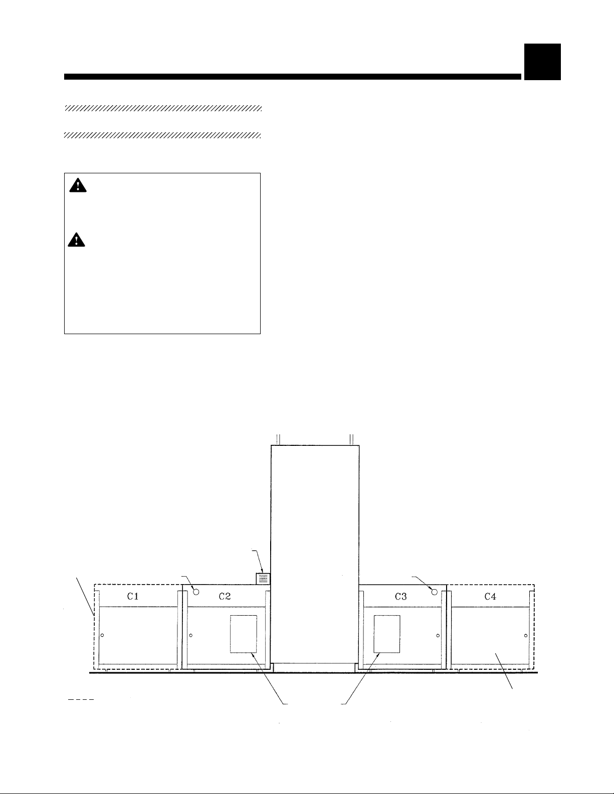
3. Place conveyor modules in order shown on the Equipment
Drawing, in correct relation to washer and building supply lines.
If modules are not at installation site, refer to Uncrating Instruc-
tions (Section 2) for proper moving instructions.
NOTE: Leave sufficient space between and around modules to
performinstallation.
4. Lock out and tag out electrical supply disconnect switch on the
washer to OFF position and close washer supply valves.
5. Remove lower service access doors from both ends of the
washer.
NOTE: Thefollowingconnectionsarerequiredtotiethemodulecold
water piping to the existing washer cold water piping.
1. Locate washer cold water piping connecting cold water inlet to
condenser (see Figure 3-1). Piping is made of two parts.
2. Remove union (located underneath sump) connecting both
pipes (see Figure 3-1, item 1).
3. Remove piping attached to cold water inlet side (see Figure 3-
1, item 2).
4. Replace piping with cold water supply piping provided (see
Figure 3-2).
3
INSTALLATION INSTRUCTIONS
Before Installing
Equipment
WARNING - PERSONAL INJURY
AND/OR EQUIPMENT DAMAGE
HAZARD: Only fully qualified ser-
vice personnel should assemble
and/or make adjustments to this
equipment. Assembly or adjust-
ments done by inexperienced, un-
qualified personnel could cause
personal injury or result in costly
damage.
Cold Water Connections

3-2
122994-142 Uncrating/Installation Instructions Installation Instructions
Cold Water Inlet to
Condenser Piping
Figure 3-1. Washer Cold Water Connections

3-3
Uncrating/Installation Instructions 122994-142
InstallationInstructions
Figure 3-2. Washer Cold Water Connections Modified
for Load/Unload Modules
Replacement Cold Water
Supply Piping
Insert Plug if Washer is not
Equipped with Condenser
Condenser Cold Water
Supply Piping

3-4
122994-142 Uncrating/Installation Instructions Installation Instructions
5. Install CW1 tee at the end of the cold water supply piping (see
Figure 3-2).
6. Connect other end of tee to condenser cold water supply piping
(see Figure 3-2).
NOTE: Ifwasherisnotequippedwithcondenser,installcoldwater
supplypipingasshowninFigure3-2,exceptinserta1/2"NPTplug
into the right-hand end of CW1 T-connection.
7. Locate manual cold water supply valve and mounting bracket
provided in box labeled "Hardware". Remove valve handle and
insert valve into mounting bracket. Install valve and mounting
bracket over pump motor base, located in washer service
compartment (see Figure 3-3), using two 8-32 x 3/8" screws
provided (CWZ and CW4 installed later, in installation proce-
dure). Reinstall valve handle. Connect cold water supply from T-
connection (CW1) to cold water supply valve (CW3) using
copper piping provided.
Figure 3-3. Cold Water and Drain Connections
Load (Soiled) End of Washer Unload (Clean) End of Washer

3-5
Uncrating/Installation Instructions 122994-142
InstallationInstructions
NOTE:Checkunderneathwashermainconsoleforthepartnumber
for the P54 AC Wiring Harness. If part number is 117-906-552 and
washer is steam heated, there is no cable to replace.
If washer is electric heated built before 3603298XXX (electric
heaters in wash chamber), P54 cable must be replaced. Replace-
ment wiring Harness Kit 117-998-643 (including drawing and har-
ness) must be ordered and installed on the washer for proper
operation of unit and load/unload module.
WasherswithS/Nafter3603298XXXareprovidedwith117-908-019
ACwiringharness.SkipSteps1trough9if unitisequippedwiththe
117-908-019 cable harness.
1. Locate P54 cable under the washer load-end control console
with printer (see Figure 3-4).
2. Remove pump detergent mounting plate to gain access to the
work area (enzyme Pump and Pump 2 are mounted on the plate
located above the detergent compartment).
3. Disconnect detergent pump electrical connections from the
mounting plate. Disconnect detergent hoses from washer and
from supply line in order to remove pump mounting plate.
4. Disconnect P54 cable assembly from under the control console.
5. FollowP54 cable and disconnect cable ends from these locations:
NOTE: Pay attention to cable routing to ease reinstallation.
a. AC10 from control console rear;
b. P55 from contactor box;
c. AC0, AC1 and AC2 (water supply valves underneath sump)
from contactor box;
d. AC4 and AC12 (steam valves) from contactor box.
6. DisconnecttheP54/P8connectionanddiscardP54andP8cables.
7. Install new P54 cable through unload (clean) end of washer and
attach to bottom of washer control console. Reconnect cable
ends to their respective locations.
8. Reinstall detergent pump mounting plate. Reconnect detergent
supply hoses to washer and supply line.
9. Reconnectdetergent pumpelectricalconnections atbackof the
mounting plate.
10. Disconnect P53 and P54 cables from washer load-end control
console with printer.
11. Using screws provided, connect end of P75 extension cable to
control console with printer P75 receptacle (see Figure 3-4).
Route cable behind detergent pump area and leave cable inside
detergent pump compartment.
12. Reconnect P53 and P54 cables to washer load-end control
console.
NOTE:Finalelectricalconnectionsarecompletedlaterintheinstal-
lation procedure.
P54 Cable Replacement

3-6
122994-142 Uncrating/Installation Instructions Installation Instructions
Figure 3-4. Electrical Connections

3-7
Uncrating/Installation Instructions 122994-142
InstallationInstructions
1. Locate door sensor holders on top of washer (see Figure 3-4).
Each holder has one empty space to accommodate new sen-
sors.
2. Install Door Open proximity sensors provided (X10 on Load end
and X11 on Unload end). Partially thread each sensor into the
appropriate holder, leaving 1/2" from door to sensor end (con-
nections to C3 electrical box are completed later in this proce-
dure).
NOTE: MakesureendofeachDoorOpensensorclearsopeningin
door frame (see Figure 3-5).
Door Open Proximity
Sensor Target
Door Closed Proximity
Sensor Target
This Area Must Clear the End of
the Door Open Proximity Sensor
Réf. #920-004-244
Figure 3-5. Door Proximity Sensor Installation
Installation of Door
Proximity Sensor

3-8
122994-142 Uncrating/Installation Instructions Installation Instructions
1. Position Load-end module (C2 or C1/C2) against load (soiled)
end of the washer. L-shaped edge of conveyor must be posi-
tioned over the load door sill.
2. Position Unload-end module (C3 or C3/C4) against unload
(clean) end of the washer. L-shaped edge of conveyor must be
positioned over the unload door sill.
NOTE: Duetofloorslope,agapmayexistbetweenL-shapededge
of conveyor and door sill.
3. Level each module, end-to-end and side-to-side, using the four
outer leveling legs with casters.
NOTE: On two-rack modules, center casters should not be in
contact with floor.
a. Open washer chamber doors. Place straight edge across the
wash chamber loading rack sliding guides and modules
sliding guides.
IMPORTANT: Do not use L-shaped edge of conveyor as a
reference for leveling. Make sure that distance between water
inlet collar and loading rack sliding guides is at 3/16" to 1/4"
(factory setting) See Figure 3-6.
b. Align modules with washer.
c. Level load-end module so that conveyor sliding guides are
1/16" higher than wash chamber guides.
d. Level unload-end module so that conveyor sliding guides are
even with wash chamber guides.
e. Once modules are leveled, adjust center casters to barely
contact the floor (two-rack modules only).
Load/Unload Modules
Installation
CAUTION: When leveling load/un-
loadmodules, useONLY themod-
ule leveling legs. DO NOT RAISE
OR LOWER WASHER LOADING
RACKFORANYREASON. Washer
loading rack is adjusted and in-
spectedatfactorytoeaseinstalla-
tion procedures.

3-9
Uncrating/Installation Instructions 122994-142
InstallationInstructions
1. Locate CW2 pipe end (cold water supply to spray head) in C3
service compartment (see Figure 3-3). Run piping under washer
to C2 service compartment, and connect to CW2 elbow located
on C2 spray head compartment.
2. Connect CW4 hose end to elbow under the cold water supply
valve in washer service compartment (see Figure 3-3).
3. In C3 service compartment, locate drain hose with plastic tee.
Remove funnel plug in washer drain. Run hose end to washer
service compartment and connect D2 tee to washer drain funnel
(see Figure 3-3).
4. Locate D1 hose end in C2 service compartment. Run hose end
to washer service compartment and connect D1 hose end to
plastic tee (see Figure 3-3).
Spray Head and Drain
Connections
Figure 3-6. Check Distance Between Water Inlet Collar
and Loading Rack Sliding Guides

3-10
122994-142 Uncrating/Installation Instructions Installation Instructions
NOTE: When connecting modules to an existing washer, shut off
andbleedexistingairsupplylinebeforedisconnectingfromwasher.
1. Run a 10' long translucent hose (1/4" OD) from C2 service
compartment to washer service compartment. Run hose up
through the cabinet channel, located along side of washer door,
to the main air supply line filter/regulator located near top of
washer (see Figure 3-7).
IMPORTANT: Make sure hose does not interfere with operation of
the washer door cable.
2. Connect A1 hose end to washer main air supply line filter/
regulator by pushing back the connector’s outer ring, inserting
hose and releasing outer ring (see Figure 3-7). Connect Cus-
tomer air supply line to the other end of the tee.
Pneumatic Connections
Figure 3-7. Pneumatic and Electrical Connections
Ref.: 122-994-091

3-11
Uncrating/Installation Instructions 122994-142
InstallationInstructions
Refer to Figure 3-9 and Figure 5-1 for all electrical connections.
1. Remove bar code reader and holder from the Hardware box.
2. Install bar code reader and holder directly onto C2 cabinet
corner, using four 8-32 x 3/8" screws provided (see Figure 3-4).
3. Run bar code reader cable underneath drip pan of C2 module
and connect end to P75 extension cable (see Figure 3-4).
4. In C2 service compartment, cut tie wrap holding P3 and P4
cable ends to pneumatic system holder.
5. Run both cable ends through washer service compartment to
C3 service compartment, and plug into B3 electrical box (see
Figure 3-9).
6. LocateP7and P8cable ends(seeFigure3-4).P7isan extension
of P53 cable and P8 is an extension of P54 cable.
7. Connect P7 and P8 cables to P7 and P8 receptacles mounted
on B3 electrical box.
8. In C3 compartment, locate and run yellow cables identified as
X10 and X11 to top of washer (see Figure 3-4) . Cables must run
behind unload (clean) end control console, to top of washer.
IMPORTANT: Makesurecablesareawayfromsteampipeanddo
not interfere with door opening.
9. Connect X10 cable end to the proximity sensor located on the
load (soiled) end of the washer (see Figure 3-4).
10. Connect X11 cable end to the proximity sensor located on the
unload (clean) end of the washer (see Figure 3-4).
11. If a two-rack unload module (C3/C4) is installed, disconnect
wire # 63 from X23 input (see Figure 5-1) and TB3- in B3
electrical box (see Table 3-1 for other configurations).
12. Connect 120 VAC building electrical supply line to the
terminal block (terminals labeled L1, N and Ground) located
in B3 electrical box (see Figure 5-1).
IMPORTANT: Electricalsupplytotheconveyormustbeaseparate
power supply line. Do not use 120 VAC power from washer (step-
down transformer is not sized to feed load/unload modules).
3. LocateA2hose(airsupplytoC3module)inC3servicecompart-
ment. Run hose under washer to C2 service compartment and
connect end marked A2 to the pneumatic tee identified as A2,
located on the pneumatic system holder (see Figure 3-7).
4. Locate A3 hose in C3 service compartment. Run hose under
washertoC2servicecompartmentandconnectittoairmanifold
identified as A3 (see Figure 3-7).
5. Turn on air supply. Verify low pressure regulator is adjusted to
20 psi and the high pressure regulator is adjusted to 55 psi.
Electrical Connections
JUMPER SETTING (J1, J2)
J1, X22 J2,X23
OFF OFF DOUBLE LOAD MODULE/
DOUBLE UNLOAD MODULE
OFF ON DOUBLE LOAD MODULE/
SINGLE UNLOAD MODULE
ON OFF SINGLE LOAD MODULE/DOUBLE
UNLOAD MODULE
ON ON SINGLE LOAD MODULE/SINGLE
UNLOAD MODULE
Table 3-1. Jumper Setting
Table of contents