amspray DSP 1400 Series User manual

DSP 1400/1550/1700/1900/2100 Series
High-Performance Airless
Sprayer
Owner’s Manual • Notice d’utilisation • Manual del Propietario
Attach the return hose.
Attacher le tuyau de retour.
Fije la manguera de retorno.
Attach the tip.
Attacher la tête de pulvérisation.
Fije la boquilla.
Attach the suction set.
Attacher l'ensemble d'aspiration.
Fije el equipo de succión.
EnglishFrançaisEspañol
1-800-880-0993
Wagner Technical Service
Need help? Call us first for answers fast.
Call Wagner Spray Tech toll-free if you have any
comments or problems with this product.
1770 Fernbrook Lane, Minneapolis, MN 55447
http://www.wagnerspraytech.com
Visit us on the world wide web!
Quick-start
Easy does it from setup to cleanup:
Printed in the U. S. A. 0601 •Form No. 0512750B
1
2
3
4
5
6
7
8
9
10
Read all WARNINGS!
Lire toutes les mises en garde!
¡Lea todas las advertencias!
Attach the paint hose.
Attacher le tuyau àfluide.
Fije la manguera de fluido.
Lubricate the packings.
Lubrifier les garnitures.
Lubrique las empaquetaduras.
Purge and prime the system
Amorcer la pompe.
Cebe la bomba.
Spray
Pulvériser
Atomice.
Store temporarily OR clean up
Ranger de façon temporaire OU nettoyer.
Almacene temporalmente Olimpie.
Maintain
Faire l'entretien.
Mantenga (De mantenimiento).

TABLE OF CONTENTS
SAFETY . . . . . . . . . . . . . . . . . . . . . . . . . . . . . . . . . . . . . . . . 2
SPECIFICATIONS . . . . . . . . . . . . . . . . . . . . . . . . . . . . . . . . 4
COMPONENTS . . . . . . . . . . . . . . . . . . . . . . . . . . . . . . . . . . 4
GENERAL DESCRIPTION . . . . . . . . . . . . . . . . . . . . . . . . . . 4
Controls and Functions . . . . . . . . . . . . . . . . . . . . . . . . . 4
SETUP . . . . . . . . . . . . . . . . . . . . . . . . . . . . . . . . . . . . . . . . . 5
Attaching the Handle - Cart Model Only . . . . . . . . . . . . . 5
Attaching the Pail Bracket - Cart Model Only . . . . . . . . . 5
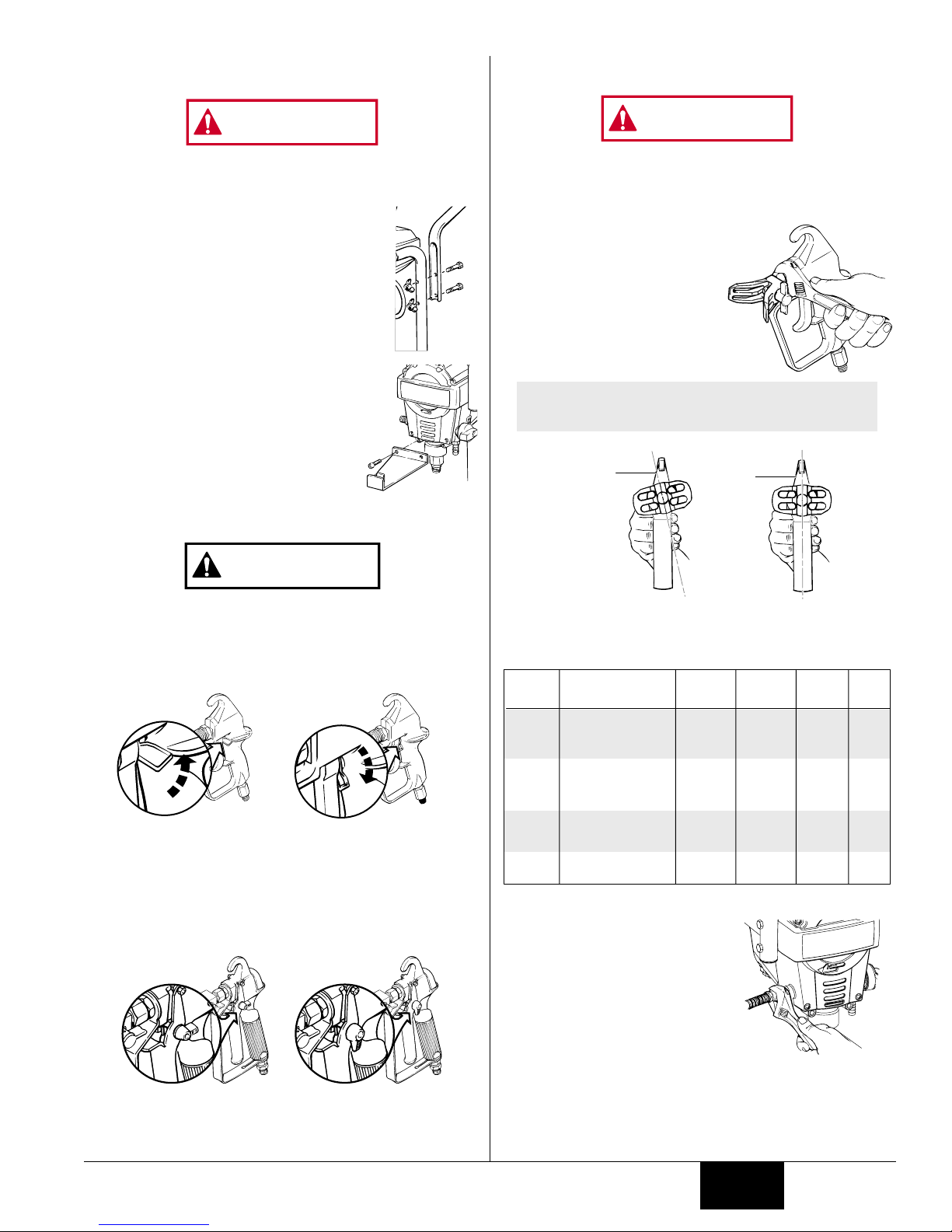
Locking and Unlocking the Gun . . . . . . . . . . . . . . . . . . . 5
Attaching the Tip . . . . . . . . . . . . . . . . . . . . . . . . . . . . . . 5
Attaching the Spray Hose. . . . . . . . . . . . . . . . . . . . . . . . 5
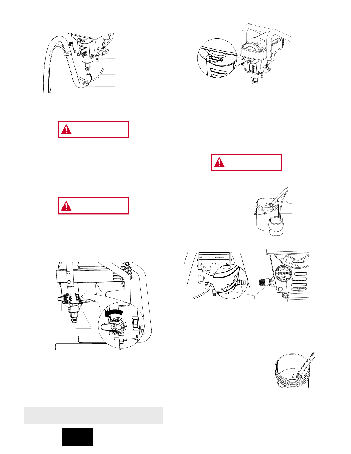
Attaching the Suction Set and Return Tube . . . . . . . . . . 5
Plugging in the Unit . . . . . . . . . . . . . . . . . . . . . . . . . . . . 6
PRESSURE RELIEF PROCEDURE . . . . . . . . . . . . . . . . . . . 6
PRIMING . . . . . . . . . . . . . . . . . . . . . . . . . . . . . . . . . . . . . . . 6
Purging and Priming . . . . . . . . . . . . . . . . . . . . . . . . . . . 6
SPRAYING . . . . . . . . . . . . . . . . . . . . . . . . . . . . . . . . . . . . . . 7
Spraying Technique . . . . . . . . . . . . . . . . . . . . . . . . . . . . 7
Practice . . . . . . . . . . . . . . . . . . . . . . . . . . . . . . . . . . . . . 7
ROUTINE CLEANING . . . . . . . . . . . . . . . . . . . . . . . . . . . . . 8
Cleaning the Spray Gun Filter . . . . . . . . . . . . . . . . . . . . 8
Unclogging the Spray Tip . . . . . . . . . . . . . . . . . . . . . . . . 8
Cleaning the Spray Tip. . . . . . . . . . . . . . . . . . . . . . . . . . 8
Cleaning the Suction Set Screen . . . . . . . . . . . . . . . . . . 8
CLEANUP AND STORAGE . . . . . . . . . . . . . . . . . . . . . . . . . 9
Short-Term/Overnight Storage . . . . . . . . . . . . . . . . . . . . 9
Long-Term Storage . . . . . . . . . . . . . . . . . . . . . . . . . . . . 9
MAINTENANCE . . . . . . . . . . . . . . . . . . . . . . . . . . . . . . . . . 10
Daily Maintenance . . . . . . . . . . . . . . . . . . . . . . . . . . . . 10
Extended Maintenance. . . . . . . . . . . . . . . . . . . . . . . . . 10
ACCESSORIES . . . . . . . . . . . . . . . . . . . . . . . . . . . . . . . . . 10
FLUID SECTION . . . . . . . . . . . . . . . . . . . . . . . . . . . . . . . . 11
PARTS LIST. . . . . . . . . . . . . . . . . . . . . . . . . . . . . . . . . . . . 12
TROUBLESHOOTING . . . . . . . . . . . . . . . . . . . . . . . . . . . . 14
WARRANTY. . . . . . . . . . . . . . . . . . . . . . . . . . . . . . . . . . . . 44
SAFETY PRECAUTIONS
This manual contains information which must be read and
understood before using the equipment. When you come to an
area which has one of the following symbols, pay particular
attention and make certain to heed the safeguard.
This symbol indicates a potential hazard which may cause
serious injury or loss of life. Important safety information
will follow.
This symbol indicates a potential hazard to you or to the
equipment. Important information that tells how to prevent
damage to the equipment or how to avoid causes of minor
injuries will follow.
THE DSP 1400 AND 1550 SERIES UNITS ARE PROVIDED
WITH A NON-RESETABLE THERMAL OVERLOAD. THE
DSP 1700, 1900 AND 2100 SERIES UNITS ARE PROVIDED
WITH A REPLACEABLE FUSE.
•Always disconnect the motor from the power supply
before working on the equipment.
NOTE: The cause of the overload should be corrected
before restarting. Take to Service Center.
CAUTION
NOTE: Notes give important information which
should be given special attention.
CAUTION
WARNING
2 © 2001 Wagner Spray Tech - All rights reserved.
HAZARD: Injection injury - A high pressure paint stream
produced by this equipment can pierce the skin
and underlying tissues, leading to serious
injury and possible amputation. SEE A
PHYSICIAN IMMEDIATELY.
DO NOT TREAT AN INJECTION INJURY AS A SIMPLE CUT!
Injection can lead to amputation. See a physician
immediately.
The maximum operating range of the gun is 3000
PSI/207BAR fluid pressure.
PREVENTION:
•NEVER aim the gun at any part of the body.
•NEVER allow any part of the body to touch the fluid
stream. DO NOT allow body to touch a leak in the fluid
hose.
•NEVER put your hand in front of the gun. Gloves will not
provide protection against an injection injury.
•ALWAYS lock the gun trigger, shut the pump off, and
release all pressure before servicing, cleaning the tip or
guard, changing tip, or leaving unattended. Pressure will
not be released by turning off the motor. The
PRIME/SPRAY knob must be turned to PRIME to relieve
the pressure. Refer to the PRESSURE RELIEF
PROCEDURE described in the pump manual.
•ALWAYS keep the tip guard in place while spraying. The
tip guard provides some protection but is mainly a warning
device.
•ALWAYS remove the spray tip before flushing or cleaning
the system.
•Paint hose can develop leaks from wear, kinking and
abuse. A leak can inject material into the skin. Inspect
the hose before each use.
•NEVER use a spray gun without a trigger lock and trigger
guard in place.
•All accessories must be rated at or above 3000 PSI/207
BAR. This includes spray tips, guns, extensions, and hose.
HAZARD: EXPLOSION OR FIRE - Solvent and paint fumes
can explode or ignite. Property damage and/or
severe injury can occur.
PREVENTION:
•Provide extensive exhaust and fresh air introduction to keep
the air within the spray area free from accumulation of
flammable vapors.
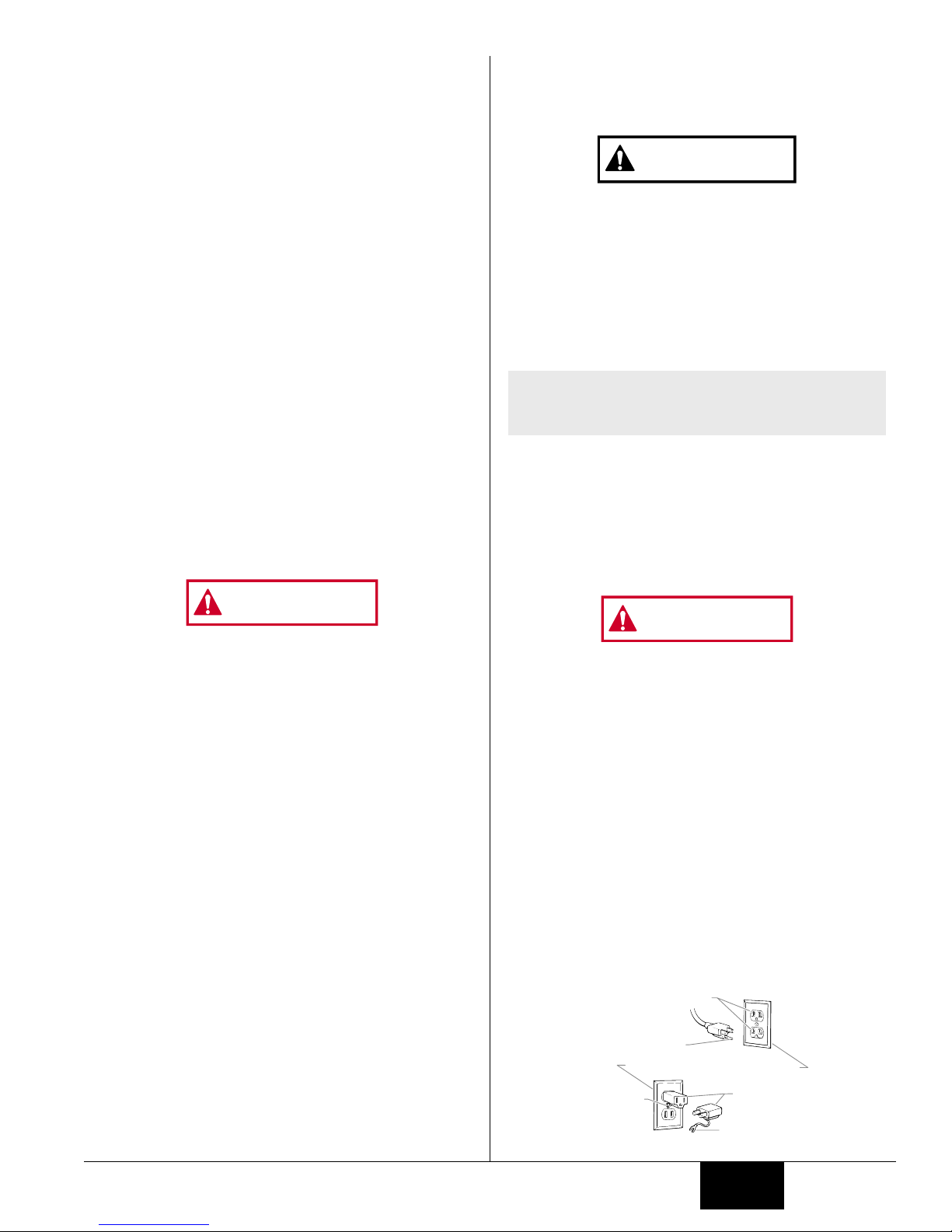
•Avoid all ignition sources such as static electric sparks,
open flames, pilot lights, and hot objects. Connecting or
disconnecting power cords or working light switches can
make sparks.
•Do not smoke in spray area.
•Fire extinguisher must be present and in good working
order.
•Place paint pump at a minimum of 3 feet (preferably more)
into a separate, well ventilated room from the spray object
or at least 20 feet from the spray object in a well ventilated
area (add more hose if necessary). Flammable vapors are
often heavier than air. Floor area must be extremely well
ventilated. The paint pump contains arcing parts that emit
spark and can ignite vapors.
•The equipment and objects in and around the spray area
must be properly grounded to prevent static sparks.
•Use only conductive or grounded high pressure fluid hose.
NOTE TO PHYSICIAN:
Injection into the skin is a traumatic injury. It is important
to treat the injury as soon as possible. DO NOT delay
treatment to research toxicity. Toxicity is a concern with
some coatings injected directly into the blood stream.
Consultation with a plastic surgeon or reconstructive
hand surgeon may be advisable.
WARNING
English

Gun must be grounded through hose connections.
•Power cord must be connected to a grounded circuit.
•Always flush unit into a separate metal container, at low
pump pressure, with spray tip removed. Hold gun firmly
against side of container to ground container and prevent
static sparks.
•Follow the material and solvent manufacturer's warnings
and instructions.
•Use extreme caution when using materials with a
flashpoint below 70°F (21°C). Flashpoint is the
temperature that a fluid can produce enough vapors to
ignite.
•Plastic can cause static sparks. Never hang plastic to
enclose a spray area. Do not use plastic drop cloths
when spraying flammable materials.
•Use lowest possible pressure to flush equipment.
GAS ENGINE (WHERE APPLICABLE)
Always place pump outside of structure in fresh air. Keep all
solvents away from the engine exhaust. Never fill fuel tank with
a running or hot engine. Hot surface can ignite spilled fuel.
Always attach ground wire from pump unit to a grounded object,
such as a metal water pipe. Refer to enigine owner’s manual
for complete safety information.
HAZARD: EXPLOSION HAZARD DUE TO INCOMPATIBLE
MATERIALS - Will cause property damage or
severe injury.
PREVENTION:
•Do not use materials containing bleach or chlorine.
•Do not use halogenated hydrocarbon solvents such as
bleach, mildewcide, methylene chloride and 1,1,1 -
trichloroethane. They are not compatible with aluminum.
•Contact your coating supplier about the compatibility of
material with aluminum.
HAZARD: HAZARDOUS VAPORS - Paints, solvents,
insecticides, and other materials can be
harmful if inhaled or come in contact with the
body. Vapors can cause severe nausea,
fainting, or poisoning.
PREVENTION:
•Use a respirator or mask if vapors can be inhaled. Read
all instructions supplied with the mask to be sure it will
provide the necessary protection.
•Wear protective eyewear.
•Wear protective clothing as required by coating
manufacturer.
HAZARD: GENERAL - can cause severe injury or
property damage.
PREVENTION:
•Read all instructions and safety precautions before
operating equipment.
•Follow all appropriate local, state, and national codes
governing ventilation, fire prevention, and operation.
•The United States Government Safety Standards have
been adopted under the Occupational Safety and Health
Act (OSHA). These standards, particularly part 1910 of
the General Standards and part 1926 of the Construction
Standards should be consulted.
•Use only manufacturer authorized parts. User assumes
all risks and liabilities when using parts that do not meet
the minimum specifications and safety requirements of the
pump manufacturer.
•Before each use, check all hoses for cuts, leaks, abrasion
or bulging of cover. Check for damage or movement of
couplings. Immediately replace the hose if any of these
conditions exist. Never repair a paint hose. Replace it
with another grounded high-pressure hose.
WARNING
•All hoses, swivels, guns, and accessories must be
pressure rated at or above 3000PSI/207 BAR.
•Do not spray outdoors on windy days.
•Wear clothing to keep paint off skin and hair.
Use only a 3-wire extension cord that has a 3-blade grounding
plug and a 3-slot receptacle that will accept the plug on the
product. Make sure your extension cord is in good condition.
When using an extension cord, be sure to use one heavy
enough to carry the current your product will draw. An
undersized cord will cause a drop in line voltage resulting in loss
of power and overheating. A 14 or 12 gauge cord is
recommended. If an extension cord is to be used outdoors, it
must be marked with the suffix W-A after the cord type
designation. For example, a designation of SJTW-A would
indicate that the cord would be appropriate for outdoor use.
GROUNDING INSTRUCTIONS
This product must be grounded. In the event of an electrical
short circuit, grounding reduces the risk of electric shock by
providing an escape wire for the electric current. This product
is equipped with a cord having a grounding wire with an
appropriate grounding plug. The plug must be plugged into an
outlet that is properly installed and grounded in accordance
with all local codes and ordinances.
Improper installation of the grounding plug can result in a
risk of electric shock.
If repair or replacement of the cord or plug is necessary, do not
connect the green grounding wire to either flat blade terminal.
The wire with insulation having a green outer surface with or
without yellow stripes is the grounding wire and must be
connected to the grounding pin.
Check with a qualified electrician or serviceman if the
grounding instructions are not completely understood, or if you
are in doubt as to whether the product is properly grounded.
Do not modify the plug provided. If the plug will not fit the
outlet, have the proper outlet installed by a qualified electrician.
This product is for use on a nominal 120 volt circuit and has a
grounding plug that looks like the plug illustrated below. A
temporary adapter which looks like the adapter illustrated in the
figure below may be used to connect this plug to a 2 pole
receptacle as shown if a properly grounded outlet is not available.
The temporary adapter should be used only until a properly
grounded outlet as shown below can be installed by a qualified
electrician. The green colored rigid ear lug or the grounding wire
extending from the adapter must be connected to a permanent
ground such as a properly grounded outlet box cover. Whenever
the adapter is used, it must be held in place by a metal screw.
Grounded Outlet
Grounding Pin
Tab for
Grounding Screw
Adapter
Metal Screw
Cover for grounded outlet box
WARNING
NOTE: Do not use more than 50 feet of hose. If you
need to paint further than 100 feet from your
power source, use more extension cord, not
more paint hose.
CAUTION
© 2001 Wagner Spray Tech - All rights reserved. 3 English

SPECIFICATIONS
Weight ..............................25 lbs. (1400)
31 lbs. (1550, 1700 and 1900)
40 lbs. (2100)
Capacity ...........................Up to .25 gallon (1 liter) per minute.
(DSP 1550 Series)
Up to .33 gallon (1.25 liters) per
minute. (cart model DSP 1700 Series)
Up to .42 gallon (1.6 liters) per
minute (cart model DSP 1900 Series)
Up to .45 gallon (1.71 liters) per
minute. (cart model DSP 2100 Series)
Power source ...................1/2 Hp universal motor (1550 Series)
5/8 Hp permanent magnet DC motor
(1700 series)
3/4 Hp permanent magnet DC motor
(1900 Series)
7/8 Hp permanent magnet DC motor
(2100 series)
Power requirement ...........15 amp minimum circuit on 115
VAC, 60 Hz current.
Generator .........................15 amp A/C.
Spraying pressure ............Up to 2800 psi.
Safety features .................Spray gun trigger lock and pressure
diffuser; built-in tip safety guard;
priming knob for safe pressure
release.
Capability..........................Sprays a variety of paints, oil base
latex, primers, stains, preservatives
and other nonabrasive materials,
including pesticides and liquid
fertilizers.
Unit Tip Size:Supplied Max. Size Supports
1400 .013 .015
1550 .013 .015
1700 .015 .017
1900 .017 .019
2100 .017 .021
COMPONENTS
The shipping carton for your painting system contains the following:
•Suction set and return tube
•Spray gun with filter
•Spray tip assembly
•25 foot long, 1/4 inch diameter pressure hose (1550)
•50 foot long, 1/4 inch diameter pressure hose (1700/1900/2100)
•Packing lubricant
GENERAL DESCRIPTION
This high performance piston pump is a precision power tool
used for spraying many types of materials. Read and follow
this instruction manual carefully for proper operating
instructions, maintenance and safety information.
Controls and Functions
ON/OFF Switch ................The ON/OFF switch turns the unit on
and off.
Suction Set .......................Fluid is drawn through the suction
set into the pump.
Fluid Section ....................A piston in the fluid section moves up
NOTE: This pump is available in two models: a stand
model and a cart model. The stand model is
shown in this manual. All information given for
the stand model applies to the cart model
except where indicated.
4 © 2001 Wagner Spray Tech - All rights reserved.
and down to create the suction that
draws fluid through the suction set.
Spray Gun ........................The spray gun controls the delivery
of the fluid being pumped.
Spray Hose ......................The spray hose connects the gun to
the pump.
Return Tube......................Fluid is sent back out through the
return tube to the original container.
PRIME/SPRAY Knob........The PRIME/SPRAY knob directs fluid
to the spray hose when set to SPRAY
or the return tube when set to PRIME.
The arrows on the PRIME/SPRAY
knob shows the rotation directions for
PRIME and SPRAY.
Pressure Control Dial .......The pressure control dial controls
the amount of force the pump uses
to push the fluid.
PRIME/SPRAY
Knob
PRIME/SPRAY
Knob
Fluid Section
Suction Set
Return Tube
ON/OFF Switch
(Rear View,
1400, 1550, 1700,1900) (Front View, 2100)
Spray Hose
Spray Gun
Pressure Control Dial
English

SETUP
Do not plug in the unit until setup is complete.
Attaching the Handle--Cart Only
1. Position the handle against the cart so that
the holes in the handle line up with the holes
in the cart.
2. Insert the bolts through the holes in the
handle and cart.
3. Tighten the wing nuts onto the bolts.
Attaching the Pail Bracket--
Cart Only
1. Position the pail bracket against the
unit so that the holes in the unit line
up with the holes in the bracket.
2. Insert the bolts through the holes in
the bracket and the unit.
3. Tighten the bolts.
Locking and Unlocking
the Gun
Always lock the trigger off when the gun is not in use.
Gun models GX-06 and GX-07
The gun is secured when the trigger lock is at a 90°angle
(perpendicular) to the trigger in either direction. To unlock the
trigger, turn the trigger lock to be in line with the trigger.
Gun models G-08 and G-10
To lock the gun, turn the trigger lock toward the gun handle.
To unlcok the gun, turn the trigger lock so that it is vertical and
pointing down.
G-08/10 unlocked
(gun will spray)
G-08/10 locked off
(gun will not spray)
GX-06/07 Gun unocked
(gun will spray)
GX-06/07 Gun locked
(gun will not spray)
CAUTION
WARNING
Attaching the Tip to the Gun
POSSIBLE INJECTION HAZARD. Do not spray without the tip
guard in place. Never trigger the gun unless the tip is in
either the spray or the unclog position. Always engage the
gun trigger lock before removing, replacing or cleaning tip.
1. Thread the spray tip onto the
gun. Tighten the nut first by
hand, then tighten more firmly
with a wrench.
Choosing the Correct Spray Gun Filter
Use the proper gun filter based on the tip size being used.
Attaching the Paint Hose
1. Be sure that the motor is turned
to OFF (o).
2. Attach the high pressure hose
to the paint hose port. Use a
wrench to tighten the paint hose
securely.
3. Attach the gun to the other end
of the high pressure hose.
Tighten securely with a wrench.
Attaching the Suction Set and Return Hose
1. Attach the suction tube to the inlet valve and tighten firmly
by hand. Be sure that the threads are straight so that the
fitting turns freely.
Part No. Tip Size Filter
Type
Mesh
Number
Qty.Color of
Filter
Body
0154918 .011 Extrafine 180 mesh
0.084 mm
red 2 pack
2 pack
2 pack
2 pack
0154675 .013 - .015 Fine 100 mesh
0.140 mm
yellow
0154842 .017 - .023 Medium 50 mesh
0.315 mm
white
0154919 .023 and up Coarse 30 mesh
0.560 mm
green
Begin
tightening
the tip at
this angle
to achieve
the desired
spray angle
when tight.
NOTE: When attaching tip to the gun, align the tip
guard as shown in figure below, then
tighten with a wrench.
WARNING
© 2001 Wagner Spray Tech - All rights reserved. 5 English

2. Press the return tube onto the return tube fitting.
3. Place the suction tube and the return tube into the paint.
4. Place the paint bucket onto the floor or hang on the pail
bracket, depending on the model of pump you have.
Always lock the gun off when it is not in use.
Plugging in the Unit
1. Check that the ON/OFF switch is in the OFF position (o).
2. Plug the sprayer into a properly grounded outlet or heavy
duty grounded extension cord.
PRESSURE RELIEF PROCEDURE
Be sure to follow the pressure relief procedure when
shutting the unit down for any purpose, including
servicing or adjusting any part of the spray system,
changing or cleaning spray tips, or preparing for cleanup.
1. Lock the spray gun off.
2. Move the ON/OFF switch to the OFF (O) position.
3. Turn the PRIME/SPRAY knob to PRIME.
PRIMING
Preparing to Prime
1. Before priming, squirt some hydraulic oil (P/N 0154908
included with unit) into the indicated area. Light
household oil can be substituted if necessary. This will
prolong seal life of the unit.
NOTE: Apply only a teaspoon amount at a time. Too
much oil may cause the oil to drip into the paint.
o
+
o
+
o
+
+
o
ON/OFF Switch
(+/o)
PRIME/SPRAY
Knob
WARNING
WARNING
Return tube
fitting
Return tube
Inlet valve
Suction set
6 © 2001 Wagner Spray Tech - All rights reserved.
Purging and Priming
If this unit is new, it is shipped with test fluid in the fluid section
to prevent corrosion during shipment and storage. If you are
going to spray latex paint, this fluid must be purged and
thoroughly cleaned out of the system. If you are going to
spray with solvent-based paint, this fluid must be purged from
the system, but thorough cleaning is not necessary.
If the pump has already been used you will need to purge the
water or solvent used in cleanup and storage.
Always keep the spray gun locked off when purging the pump.
Purging and Priming the Pump for Latex Paint
1. Secure the return tube into
a waste container.
2. Place a full container of
paint underneath the
suction tube.
3. Turn the pressure control dial
to minumum pressure (-).
4. Turn the PRIME/SPRAY knob to PRIME.
5. Move the ON/OFF switch to the ON position. If unit does
not start, turn pressure control dial one to two turns until
unit turns on.
6. The unit will begin to draw paint up the suction tube, into
the pump, and out the return tube. Let the unit cycle long
enough to remove test fluid from the pump, or until paint is
coming from the return tube.
7. Remove the return tube from the
waste container and place it in its
operating position above the
container of paint.
8. Keep circulating the paint through the
system until the paint coming out of
the return tube is free of air bubbles.
9. Move the ON/OFF switch to the OFF position.
The pump is now purged. Skip to Purging and Priming the
Spray Hose.
(Rear View,
1400, 1550, 1700,1900) (Front View, 2100)
Pressure Control Dial
Return
tube
Suction
tube
WARNING
English

Purging and Priming the Spray Hose
After the pump is purged and primed, you must do the same
for the spray hose.
1. Lock the spray gun off.
2. Remove the spray tip from the gun.
3. Turn the PRIME/SPRAY knob to SPRAY.
4. Be certain that the spray gun is unlocked and trigger it into
a waste container. Hold the trigger until all air, water, or
solvent is purged from the spray hose and paint is flowing
freely.
Keep hands clear of the stream of fluid coming from the
spray gun.
Using a metal container, ground the
gun by holding it against the edge of
the container while flushing. Failure to
do so may lead to a static electric
discharge which may cause a fire.
If the PRIME/SPRAY knob is still on
SPRAY, there will be high pressure in the hose and spray
gun until the PRIME/SPRAY knob is turned to PRIME.
5. Turn the PRIME/SPRAY knob to PRIME.
6. Be certain that the spray gun is unlocked and trigger it into
the waste container to be sure that no pressure is left in
the hose.
7. Lock the spray gun off.
8. Attach the spray tip.
SPRAYING
Spraying Technique
The key to a good paint job is an even coating over the entire
surface. This is done by using even strokes. Keep your arm
moving at a constant speed and keep the spray gun at a
constant distance from the surface. The best spraying distance
is 10 to 12 inches between the spray tip and the surface.
Keep the spray gun at right angles to the surface. This means
Heavy Coat
Do not flex wrist while spraying.
Light Coat Light Coat
WARNING
WARNING
G-08/10 locked off
(gun will not spray)
GX-06/07 Gun locked
(gun will not spray)
moving your entire arm back and forth rather than just flexing
your wrist.
Keep the spray gun perpendicular to the surface, otherwise
one end of the pattern will be thicker than the other.
The spray gun should be triggered by turning it on and off with
each stroke. This will save paint and avoid paint buildup at the
end of the stroke. Do not trigger the gun during the middle of a
stroke. This will result in an uneven spray and splotchy coverage.
Overlap each stroke by about 30%. This will ensure an even coating.
When you stop painting, lock the gun trigger lock, and set the
priming knob to PRIME. Turn the motor switch to OFF and
unplug the sprayer.
If you expect to be gone more than 1 hour, follow the short
term clean up procedure described in the CLEANUP section of
this manual.
Practice
Be sure that the paint hose is free of kinks and clear of
objects with sharp cutting edges.
1. Turn the PRIME/SPRAY knob to SPRAY.
2. Turn the pressure contol dial to its highest setting (+).
The spray hose should stiffen as paint begins to flow
through it.
3. When paint reaches the spray tip, spray a test area to
check the spray pattern.
CAUTION
Proper way to trigger the spray gun
Approximately
10 to 12 inches
Keep stroke
even
Start stroke End strokePull trigger Release triggerKeep steady
Approximately
10 to 12 inches
Wrong way
Right way
Keep stroke smooth and at an even speed.
Even coat throughout
Approximately
10 to 12 inches
© 2001 Wagner Spray Tech - All rights reserved. 7 English

CLEAN UP
Cleaning the Spray Gun Filter
The spray gun includes a filter to catch
dirt particles before they reach the spray
tip. If this filter becomes clogged or
obstructed it will reduce the flow of
paint, changing the spray pattern and
possibly damaging the filter.
Clean the filter with a brush. Never
poke the filter with a sharp instrument.
This filter must be cleaned daily. If the
material being used is old or contains
hardened particles, then the filter should be cleaned
approximately every 4 hours.
If the filter is not cleaned at the proper time, it will plug from
the top down. When there is about 1 inch of filter that isn't
plugged, the heavy flow of paint will blow pin holes in the filter.
Holes in the filter will allow unwanted particles to get into the
spray tip, causing the spray tip to clog.
Changing the
Filter
1. Unscrew fitting #6 from
the gun, making sure not
to lose the spring #5.
Remove the old filter.
2. Slide the new filter,
tapered end first, into the
gun housing.
3. Replace the spring #5 and the fitting #6. Tighten with a
wrench.
NOTE: The tapered end of the filter must be loaded
properly into the gun. Improper assembly
will result in a plugged tip.
4
1
3
2
5
6
Pin hole
Filter top
Good spray pattern
Paint tailing pattern
NOTE: The pressure control dial should be set at the
maximum setting (+) in most cases when
using thicker viscosity materials such as latex
paints. You may have to lower the pressure
setting (-) when using thinner viscosity
materials such as stains. If the pressure is
set too high, you will over atomize and waste
paint. If the pressure is set too low, tailing
will appear or the paint will spatter out in
gobs rather than a fine spray.
8 © 2001 Wagner Spray Tech - All rights reserved.
Unclogging the Spray Tip
Do not attempt to unclog or clean the tip with your finger.
Do not use a needle or other sharp pointed instrument to
clean the tip. The hard tungsten carbide is brittle and can
be chipped.
The spray gun is equipped with a reversible tip which allows
you to blow out any particles of old paint or other contaminants
that may obstruct the paint flow through the tip. If the spray
pattern becomes distorted or stops completely while the gun is
triggered, follow these steps:
1. Release the trigger and lock the gun off.
2. Rotate the reversible tip cylinder arrow
180°so that the point of the arrow is
toward the rear of the gun.
3. Unlock the gun and squeeze the trigger,
pointing the gun at a scrap piece of
wood or cardboard. This allows pressure in the spray
hose to blow out the obstruction. When the nozzle is
clean, paint will come out in a straight, high pressure
stream.
4. Release the trigger and lock the gun off.
5. Reverse the tip so the arrow points forward again.
6. Unlock the gun and resume spraying.
Cleaning the Spray Tip
1. Turn the PRIME/SPRAY knob to PRIME. This will bleed
off the pressure in the spray hose and filter. Trigger the
gun to be sure that the pressure is gone. Refer to the
PRESSURE RELIEF PROCEDURE section.
2. Lock the spray gun off.
3. Remove the spray tip assembly from the gun with a
wrench.
4. Turn the spray tip so that the arrow tab is perpendicular to
the spray guard and pull the tip out.
5. Push the seal and washer out the back end of the tip
guard.
6. Wash all the tip assembly parts with soapy water or an
appropriate solvent.
NOTE: If spraying with latex paint, use warm soapy
water for cleaning. If using oil or alkyd-based
paints, use mineral spirits of paint thinner.
Refer to the paint manufacturer’s instructions
for specific recommendations.
NOTE: It is sometimes necessary to relieve pump
pressure by turning the PRIME/SPRAY knob to
PRIME before rotating the reversible tip.
NOTE: If the spray tip remains clogged, follow the
Cleaning the Spray Tip procedure.
CAUTION
WARNING
English

Cleaning the Suction Set Screen
The screen at the bottom of the suction
set may also need cleaning. Check it
every time you change paint buckets.
Remove the screen by pulling it out of the
retainer with a plier. Clean the screen with
water or solvent and a soft-bristle brush.
Short Term Storage (up to
16 hours)
Shutdown
1. Lock the spray gun off.
2. Turn the PRIME/SPRAY knob to PRIME.
3. Turn the motor switch to OFF (O) and unplug the sprayer.
4. For latex materials only, pour 1/2 cup water slowly on the
top of the paint to prevent the paint from drying.
5. Wrap the spray gun assembly in a damp cloth and place it
in a plastic bag. Seal the bag shut.
6. Place the sprayer in a safe place out of the sun for short-
term storage.
Startup
1. Remove the gun from the plastic bag.
2. Stir the water into the paint for latex materials. Remove
the seal from the paint bucket and stir the paint for all
other materials.
3. Check to be sure that the PRIME/SPRAY knob is set to
PRIME.
4. Plug sprayer in and turn the motor switch to ON.
5. Turn the PRIME/SPRAY knob to SPRAY.
6. Test the sprayer on a practice piece and begin spraying.
Long-term Storage (16 + hours)
Special clean up instructions for use with flammable
solvents:
IMPORTANT
•ALWAYS FLUSH SPRAY GUN AT LEAST ONE (1)
HOSE LENGTH AWAY FROM SPRAY PUMP.
•If collecting flushed solvents in one (1) gallon metal
container, place it into an empty five (5) gallon metal
container, then flush.
•Area must be free of vapors.
•Follow all cleanup instructions.
Cleaning the Suction Tube
1. Lock the spray gun off.
2. Turn the PRIME/SPRAY knob to PRIME
3. Turn the motor switch to OFF and unplug the sprayer.
4. Remove the suction tube from the paint and hold it above
a bucket of water or solvent. Leave the return tube in the
paint bucket.
WARNING
NOTE: Follow these steps when using latex paints
only. If using materials that are oil-based,
follow the long-term storage steps.
Do not use mineral spirits or paint thinner on latex paint,
or the mixture will turn into a jelly-like substance which is
difficult to remove.
5. Plug the sprayer in and turn the motor switch to ON.
6. Trigger the gun to relieve pressure and lock the gun.
7. Remove the spray tip assembly and place it into a
container of water or appropriate solvent for the type of
material with which you are spraying.
8. Place the attached suction tube and return tube into a
container of water or appropriate solvent for the type of
material with which you are spraying.
9. Let the water or solvent circulate for 2-3 minutes to flush
paint out of the pump, the suction tube and the return tube.
Cleaning the Paint Hose
1. To save paint left in the hose,
release the gun trigger lock, place
the gun body with the spray tip
removed against the paint
container, and carefully trigger the
gun into the container.
2. Turn the PRIME/SPRAY knob to
SPRAY.
3. As soon as the water or solvent starts to come into the
bucket, release the trigger.
4. Change to clean water or solvent and continue circulating
for another 5 minutes to thoroughly clean the hose, pump
and spray gun.
5. Turn the PRIME/SPRAY knob to PRIME.
6. Trigger the gun to remove any pressure which may still be
in the hose.
7. Lock the spray gun off.
8. Turn the motor switch to OFF.
9. Cover the paint container and set it aside.
Cleaning the Gun
1. Remove the spray gun from paint hose using a wrench.
2. Remove the filter housing from the gun. Place the gun
and the filter assembly into a container of water or solvent
to soak.
3. Clean the spray tip and gun filter with a soft brush.
Assemble the spray tip in the cleaning position with the
arrow pointing to the back of the gun.
4. Attach the paint hose to the gun and tighten using a wrench.
5. Turn the motor switch to ON.
6. Unlock the gun.
7. Turn the PRIME/SPRAY knob to SPRAY and point the gun
to the side of the cleaning bucket.
CAUTION
NOTE: If spraying with latex paint, use warm soapy
water for cleaning. If using oil or alkyd-based
paints, use mineral spirits or paint thinner.
© 2001 Wagner Spray Tech - All rights reserved. 9 English

8. Continue to trigger the gun for
approximately 30 seconds.
9. Turn the PRIME/SPRAY knob to
PRIME.
10. Trigger the gun to remove any
pressure which may still be in
the hose.
11. Lock the spray gun off.
12. Turn the motor switch to OFF.
Preparing the Sprayer for Long-term Storage
1. Remove the tip assembly and raise the suction set above
the cleaning solution.
2. Turn the motor to ON.
3. Turn the PRIME/SPRAY knob to SPRAY.
4. Remove the large suction tube from the inlet valve and
point the gun into the cleaning bucket.
5. Unlock the gun and trigger it into the cleaning bucket until
the hose is pumped dry.
6. Turn the PRIME/SPRAY knob to PRIME.
7. Clean the threads of
the inlet valve with a
damp cloth.
8. Fill the inlet valve with a
light household oil.
Slowly increase the
pressure to distribute the
oil through the pump.
Also add oil to top
bushing of unit in order
to prolong seal life.
9. Turn the PRIME/SPRAY
knob to SPRAY to distribute the oil.
10. Replace the large suction tube onto the inlet valve.
11. Turn the PRIME/SPRAY knob to PRIME.
12. Trigger the gun to remove any pressure which may still be
in the hose.
13. Lock the spray gun off.
14. Turn the motor switch to OFF.
15. Remove and clean the suction set filter in clean water or
the appropriate solvent. Use a soft brush. Return the
suction set filter to its original position.
16. Wipe the entire unit, hose and gun with a damp cloth to
remove accumulated paint.
MAINTENANCE
Daily Maintenance
The only daily maintenance necessary is thorough cleaning.
NOTE: Thorough cleaning and lubrication of the
sprayer is the most important step you can
take to ensure proper operation after storage.
NOTE: If you spray oil-or solvent-based material, the
following cleaning steps must be followed in
addition to the steps in the owner’s manual to
properly clean and lubricate the pump before
storage.
1. Flush the pump with the appropriate solvent as
recommended on the paint manufacturer’s label.
Follow the steps in the owner’s manual.
2. After flushing with solvent, run warm, soapy water
through the pump to remove the solvent material. The
solvent must be removed to allow proper lubrication of
the pump prior to storage.
3. Lubricate the pump using a light household oil as
described in the owner’s manual.
Inlet
valve
10 © 2001 Wagner Spray Tech - All rights reserved.
Follow the cleaning procedures in this manual.
Extended Maintenance
Some pump parts eventually wear out from use and must be
replaced. The following list indicates the available repair kits
for the parts replaced by each kit. However, pump
performance is the only reliable indicator of when to replace
wear parts. Refer to the Troubleshooting section for more
information on when to use these kits.
Kit Part # Description
0512221 Fluid Section Seal Kit (1400 and 1550 Series)
0512222 Valve Replacement Kit (1400 and 1550 Series)
0512223 Fluid Section Seal Kit (1700,1900, 2100 Series)
0512224 Valve Replacement Kit (1700,1900, 2100 Series)
ACCESSORIES
Part # Description
0154908 Separating Oil
0154830 Hose, Whip End, 5’x 3/16”
0270192 Hose, Wireless, 25’x 1/4"
0270118 Hose, Wireless, 50’x 1/4"
0093896 Hose Connector, 1/4”x 1/4”M
0088154 Pressure Gauge
0512130 Tip Extension, 12”
0512131 Tip Extension, 24”
0152001 Power Roller Gun Attachment
0155206 9" Roller Cover, 3/8”Nap
0152307 9" Roller Cover, 1/2”Nap
0155208 9" Roller Cover, 3/4”Nap
0152310 9" Roller Cover, 1-1/4”Nap
0501002 GX-08 Four Finger Metal Airless Spray Gun
0501004 GX-07 Two Finger Metal Airless Spray Gun
0501026 GX-06 Two Finger Plastic Airless Spray Gun
0501029 GX-10 Two Finger Metal Airless Spray Gun w/Swivel
0501010 Guard Assembly, F-Thread
0501011 Guard Assembly, G-Thread
0512132 3 Foot Pole Extension w/Swivel
0512133 6 Foot Pole Extension w/Swivel
0154839 All Guard Pump Protector
0512134 180 Degree Swivel
0512135 F- to G-Thread Adapter
0154832 Suction Tube Filter (2 Pack)
0501411 411 Trade Spray Tip
0501413 413 Trade Spray Tip
0501415 415 Trade Spray Tip
0501417 417 Trade Spray Tip
0501419 419 Trade Spray Tip
0501515 515 Trade Spray Tip
0501517 517 Trade Spray Tip
0501519 519 Trade Spray Tip
0093930 Anti-Seize Compound
0156113 TR-10 Telescoping Roller, 9", 3/8" Nap
Choosing the Correct Spray Gun Filter
Use the proper gun filter based on the type of material being
applied as shown below.
Part No. Tip Size Filter
Type
Mesh
Number
Qty.Color of
Filter
Body
0154918 .011 Extrafine 180 mesh
0.084 mm
red 2 pack
2 pack
2 pack
2 pack
0154675 .013 - .015 Fine 100 mesh
0.140 mm
yellow
0154842 .017 - .023 Medium 50 mesh
0.315 mm
white
0154919 .023 and up Coarse 30 mesh
0.560 mm
green
English

Disassembly of the Fluid Section
1. Remove the suction set.
2. Remove the front cover and the four
screws that secure it using a T20
Torx head driver.
3. Remove the yoke screw and washer
that secures the dowel pin. The
dowel pin connects the yoke to the
piston.
4. Using the pliers, pull the dowel pin
out.
5a. For model 1400 and 1550, rotate the pump shaft so the
piston is in the top dead center position. This can be
done by pushing on the yoke. This is required to
disassemble all the parts.
5b. For models 1700/1900/2100, Inspect the yoke assembly
and piston. In order to remove all the necessary parts, the
piston must not be in the bottom dead center position. If
the piston is at the bottom of the stroke, install the front
cover and screws, turn the pump on briefly to index the
piston, unplug the unit, and repeat step 2.
6. Unscrew and remove the inlet valve assembly using an
adjustable wrench.
7. Remove the piston assembly by pushing down on the
piston near the yoke.
8. Uscrew and remove the top nut using and adjustable wrench.
9. Remove the worn seals using a flat head screwdriver or
punch. Remove the top seal from the top and the bottom
seal from the bottom by pressing against the side of the
seal and popping it out. Be sure not to scratch the
housing where the seals are located.
10. Clean the area where the new seals are to be installed.
Assembly of the Fluid Section
1. Lubricate the new top seal with Amspray Separating Oil
(P/N 0154908) or light household oil and by hand place the
seal (cup side of seal down) into the top port of the housing.
2. Place the top nut into the top of the housing and tighten
with an adjustable wrench. This will drive the top seal into
the correct position.
3. Turn the pump upside down. Place the two (2) large O-
rings over the new plastic bottom seal, lubricate similar to
the top seal, and place the bottom seal with O-rings into
the bottom (inlet) of housing by hand. Insert the inlet valve
and thread into position to properly seat the seal.
Remove inlet and go to step four (4).
4. Push the new piston into the bottom (inlet) of the housing
and align with the yoke. A ruber mallet may be used. Be
careful not to damage the piston.
5. Install the dowel pin to connect the yoke to the piston.
The piston may have to be moved up or down to do this.
6. Install the yoke screw and washer to secure the dowel pin.
7. Install the new O-ring on the inlet assembly, lubricate,
thread into the bottom (inlet) of the housing, and tighten
with an adjustable wrench. This will drive the bottom seal
into the correct position.
8. Turn pump right side up and apply a few drops of
Amspray Separating Oil or light household oil between the
top nut and piston. This will prolong the seal life.
9. Install front cover and four (4) screws.
10. Install the suction set.
Dowel
Screw
0512221
(1400/1550
Kit)
0512223
(1700/1900/
2100 Kit)
0512221
(1400/1550
Kit)
0512223
(1700/1900/
2100 Kit)
Washer
Retaining
Ring
Yoke
Piston
Assembly
Top Seal
(cup down)
Top Nut
Bottom
Seal
O-ring
Inlet Valve
Assembly
Bottom Seal
(Cross-Section)
© 2001 Wagner Spray Tech - All rights reserved. 11 English
FLUID SECTION SEAL REPLACEMENT INSTRUCTIONS
KIT 0512221 (Models 1400/1550) -- KIT 0512223 (Models 1700/1900/2100)
Always wear protective eye wear while servicing the pump. Be sure to follow the PRESSURE RELIEF PROCEDURE when
shutting the unit down for any purpose, including servicing or adjusting. After performing the pressure relief procedure, be
sure to unplug the unit before servicing or adjusting.
Area must be free of solvents and paint fumes.
WARNING

PARTS LIST
GX-06/07 Spray Gun (1550/1700)
Item Part # Description Quantity
1 0512120 Plastic gun assembly............................1
0512121 Metal gun assembly..............................1
2 0501011 Guard Assembly ...................................1
3 0501413 Tip* ........................................................1
4 0154675 Filter assembly, 100 mesh....................1
5 0043590 Spring, filter...........................................1
6 0278357 Cap, filter housing.................................1
*See listing in Accessories
G-08 Spray Gun (1900)
Item Part # Description Quantity
1 Refer to Accessories, page 10
2 0501011 Holder assembly...................................1
3 0149342 Diffuser, 7/8" .........................................1
4 0149366 Tigger guard .........................................1
5 0149700 Valve spring unit ...................................1
6 0043211 Packing .................................................1
7 9922703 Snap ring ..............................................1
8 0149377 Pin M-4 .................................................1
9 9910403 Nut, cap M-4.........................................2
10 9930818 Sliding pin .............................................2
11 9910201 Hex nut .................................................1
12 0149367 Retainer block.......................................1
13 0149362 Gun housing .........................................1
14 0043303 Washer..................................................1
15 0149369 Handle ..................................................1
16 Filter ...................................................1*
17 0043590 Spring ...................................................1
18 9970123 Sealing ring...........................................1
19 0071321 Fitting ....................................................1
20 0149210 Trigger assembly ..................................1
10
11
12
13
14
15
16
18
19
17
9
8
7
6
5
4
3
2
120
4
1
3
2
5
6
12 © 2001 Wagner Spray Tech - All rights reserved.
G-10 Spray Gun (2100)
Item Part # Description Quantity
1 Tip (Refer to Accessories, page 10)
2 0149342 Diffuser .................................................1
3 0149366 Trigger guard ........................................1
4 0149700 Valve union assembly...........................1
5 0043211 Packing .................................................1
6 9922703 Snap ring ..............................................1
7 0149377 Pin M-4 .................................................1
8 9910403 Nut, cap ................................................2
9 9930818 Sliding pin .............................................2
10 9910201 Hex nut .................................................1
11 0149368 Retainer block.......................................1
12 0149361 Gun housing .........................................1
13 0043303 Washer..................................................1
14 0149370 Handle ..................................................1
15 Filter ....................................................1*
16 0043590 Spring ...................................................1
17 9970123 Sealing ring...........................................1
18 0071321 Fitting ....................................................1
19 0279185 Collar assembly ....................................1
20 0149211 Trigger assembly ..................................1
*See page 10 for additional filter sizes.
1
2
3
4
5
6
7
8
9
10
11
12
13
14
15
17
18
19
16
20
English

Suction Set (1550, 1700, 1900, 2100)
Item Part # Description Quantity
1 0512220 Suction set assembly............................1
2 0512389 Return tube...........................................1
3 9885553 Return tube fitting ....................................1
4 0154832 Filter......................................................1
5 0512390 Clip........................................................3
Suction Set (1400)
Item Part # Description Quantity
1 0512215 Suction set assembly............................1
2 9885553 Return tube fitting ....................................1
3 0154832 Filter......................................................1
Paint Hose
Part # Description
0270192 1/4” x 25’ Hose (1550)
0270118 1/4” x 50’ Hose (1700,1900, and 2100)
1
2
3
1
2
3
4
5
Cart Assembly (1550/1700/1900/2100)
Item Part # Description Quantity
1 0512369 Handle (1550, 1700, 1900). . . . . . . . . 1
0512426 Handle (2100) . . . . . . . . . . . . . . . . . . 1
2 9800108 Bolt (1550, 1700, 1900) . . . . . . . . . . . 4
9802518 Bolt (2100) . . . . . . . . . . . . . . . . . . . . . 4
9821503 Washer (1550, 1700, 1900) . . . . . . . . 4
9810111 Nut (1550, 1700, 1900) . . . . . . . . . . . 4
0288661 Knob Handle (2100) . . . . . . . . . . . . . . 4
3 0512336 Stand (1400) . . . . . . . . . . . . . . . . . . . 1
0512383 Cart (1550) . . . . . . . . . . . . . . . . . . . . 1
0512368 Cart (1700) . . . . . . . . . . . . . . . . . . . . 1
0512385 Cart (1900) . . . . . . . . . . . . . . . . . . . . 1
0512425 Cart (2100) . . . . . . . . . . . . . . . . . . . . 1
4 0512383 Wheel (1550) . . . . . . . . . . . . . . . . . . . 2
0512397 Wheel (1700) . . . . . . . . . . . . . . . . . . . 2
0278373 Wheel (1900, 2100) . . . . . . . . . . . . . . 2
5 0275728 Cap (1550, 1700) . . . . . . . . . . . . . . . . 2
9890104 Cap (1900, 2100) . . . . . . . . . . . . . . . . 2
6 9885546 Plug . . . . . . . . . . . . . . . . . . . . . . . . . . 1
0294635 Plug (2100) . . . . . . . . . . . . . . . . . . . . 1
7 0512355 Pail Bracket . . . . . . . . . . . . . . . . . . . . 1
8 0512384 Hose Bracket (1550, 1700, 1900) . . . . 1
1
5
6
4
3
2
8
7
© 2001 Wagner Spray Tech - All rights reserved. 13 English

14 © 2001 Wagner Spray Tech - All rights reserved.
English
Problem
A. The sprayer does not start.
B. The sprayer starts but does
not draw in paint when the
PRIME/SPRAY knob is set to
PRIME.
C. The sprayer draws up paint
but the pressure drops when
the gun is triggered.
D. The PRIME/SPRAY valve is
on SPRAY and there is flow
through the return tube.
E. The spray gun leaks.
F. The tip assembly leaks.
G. The spray gun will not spray.
H. The paint pattern is tailing.
Cause
1. The sprayer is not plugged in.
2. The ON/OFF switch is set to OFF.
3. A fuse is blown in the sprayer.
4. No voltage is coming from the wall plug.
5. The sprayer was turned off while still under
pressure.
6. The extension cord is damaged or has too
low a capacity.
7. There is a problem with the motor.
1. The unit will not prime properly or has lost prime.
2. The paint bucket is empty or the suction
tube is not totally immersed in the paint.
3. The suction set is clogged.
4. The suction tube is loose at the inlet valve.
5. The inlet or outlet valve is stuck.
6. The PRIME/SPRAY valve is plugged.
7. The inlet valve is worn or damaged.
1. The spray tip is worn.
2. The suction set screen is clogged.
3. The gun or spray tip filter is plugged.
4. The paint is too heavy or coarse.
5. The outlet valve assembly is dirty or worn.
6. The inlet valve assembly is damaged or worn.
1. The PRIME/SPRAY valve is dirty or worn.
1. Internal parts of the gun are worn
or dirty.
1. The tip was assembled incorrectly.
2. A seal is worn.
1. The spray tip, the gun filter or the tip filter is
plugged.
2. The spray tip is in the CLEAN position.
1. The pressure is set too low.
2. The gun, the tip, or the suction filter
is plugged.
3. The suction tube is loose at the inlet valve.
4. The tip is worn.
5. The paint is too thick.
6. Pressure loss.
Solution
1. Plug the sprayer in.
2. Turn the ON/OFF switch to ON.
3. Take sprayer to Wagner Authorized Service Center
4. Properly test the power supply voltage.
5. Turn pressure control knob to maximum setting (+).
6. Replace the extension cord.
7. Take the sprayer to a Wagner Authorized Service Center.
1. Try to prime the unit again.
2. Refill the bucket or immerse the suction tube in
paint.
3. Clean the suction set.
4. Clean the tube connection and tighten it securely.
5. Clean the inlet and outlet valves and replace any
worn parts.* Inlet may be stuck from old paint.
Insert allen wrench to release (see figure 1 below).
6. Take sprayer to Wagner Authorized Service Center.
7. Replace the inlet valve.*
1. Replace the spray tip with a new tip.**
2. Clean the suction set screen.
3. Clean or replace the proper filter. Always keep
extra filters on hand.
4. Thin or strain the paint.
5. Clean or replace the outlet valve assembly.*
6. Replace the inlet valve.*
1. Take sprayer to Wagner Authorized Service Center.
1. Take the sprayer to a Wagner Authorized Service
Center.
1. Check the tip assembly and assemble properly.
2. Replace the seal.*
1. Clean the spray tip, gun filter or tip filter.
2. Put the tip in the SPRAY position.
1. Increase the pressure.
2. Clean the filters.
3. Tighten the suction tube fitting.
4. Replace the spray tip.
5. Thin the paint.
6. Refer to Causes and Solutions for problem B.
TROUBLESHOOTING
* Special repair kits with instructions are available for these procedures. Refer to the Maintenance section of this manual for a list
of the kits and their part numbers.
** Additional parts are available for this procedure. Refer to the Accessories section of this manual for a list of the parts and their
part numbers.
Figure 1
NOTE: The electric motor should always be kept clean
and dry. Paint acts as an insulator. Too much
paint on the motor will cause the motor to
overheat.

TABLE DES MATIÈRES
SÉCURITE . . . . . . . . . . . . . . . . . . . . . . . . . . . . . . . . . . . . . 15
SPECIFICATION . . . . . . . . . . . . . . . . . . . . . . . . . . . . . . . . 17
COMPOSANTS . . . . . . . . . . . . . . . . . . . . . . . . . . . . . . . . . 17
DESCRIPTION GÉNÉRALE . . . . . . . . . . . . . . . . . . . . . . . . 17
Commandes et fonctions . . . . . . . . . . . . . . . . . . . . . . . 17
MONTAGE . . . . . . . . . . . . . . . . . . . . . . . . . . . . . . . . . . . . . 18
Fixation de la poignée-Modèle sur chariot seulement . . 18
Fixation de la patte de fixation du seau-Modèle sur chariot .
seulement. . . . . . . . . . . . . . . . . . . . . . . . . . . . . . . . . . . . . 18
Verrouillage et déverouillage du pistolet . . . . . . . . . . . . 18
Comment attacher la tête . . . . . . . . . . . . . . . . . . . . . . . 18
Fixation du tuyau de pulvérisation . . . . . . . . . . . . . . . . 19
Fixation de l’ensemble d’aspiration et du tube de retour 18
Branchement de l’appereil . . . . . . . . . . . . . . . . . . . . . . 18
LIMITATION DE LA PRESSION PROCÉDURE. . . . . . . . . . 18
AMORÇAGE . . . . . . . . . . . . . . . . . . . . . . . . . . . . . . . . . . . 18
Purge et amorçage . . . . . . . . . . . . . . . . . . . . . . . . . . . 18
PULVÉRISATION . . . . . . . . . . . . . . . . . . . . . . . . . . . . . . . . 20
Technique de pulvérisation . . . . . . . . . . . . . . . . . . . . . . 20
Practique . . . . . . . . . . . . . . . . . . . . . . . . . . . . . . . . . . . 21
NETTOYAGE D’ENTRETIEN . . . . . . . . . . . . . . . . . . . . . . . 21
Nettoyage du filtre du pistolet . . . . . . . . . . . . . . . . . . . . 21
Débouchage de la tête du pulvérisateur . . . . . . . . . . . . 21
Nettoyage de la tête du pulvérisateur . . . . . . . . . . . . . . 22
Nettoyage de l’écran de l’ensemble d’aspiration . . . . . . 22
NETTOYAGE APRÈS PULVÉRISATION ET ENTREPOSAGE. 22
Entresposage àcourt terme / de nuit . . . . . . . . . . . . . . 22
Rangement àlong terme . . . . . . . . . . . . . . . . . . . . . . . 23
MAINTENANCE . . . . . . . . . . . . . . . . . . . . . . . . . . . . . . . . . 24
Entretien quotidien . . . . . . . . . . . . . . . . . . . . . . . . . . . . 24
Entretien prolongé. . . . . . . . . . . . . . . . . . . . . . . . . . . . 24
ACCESSOIRES . . . . . . . . . . . . . . . . . . . . . . . . . . . . . . . . . 24
COMPARTIMENT LIQUIDE . . . . . . . . . . . . . . . . . . . . . . . . 25
LISTE DE PIÉCES . . . . . . . . . . . . . . . . . . . . . . . . . . . . . . . 27
EN CAS DE PROLEME . . . . . . . . . . . . . . . . . . . . . . . . . . . 28
GARANTIE LIMITÉE . . . . . . . . . . . . . . . . . . . . . . . . . . . . . 44
MESURES DE SECURITÉ
Le présent manuel comprend des renseignements devant être
lus attentivement avant toute utilisation de l'appareil. Lorsque
l'un des symboles suivants apparaît, il est recommandéd'être
particulièrement attentif et de tenir compte des mesures de
sécuritéindiquées.
Ce symbole indique un danger potentiel pouvant causer des
blessures graves ou même mortelles. Des renseignements
importants sur la sécurité sont également indiqués.
Ce symbole indique un danger potentiel pouvant causer des
blessures corporelles ou des dommages àl'équipement. Des
renseignements importants sur la façon de prévenir tout
dommage àl'équipement ou toute blessure corporelle mineure
sont également indiqués.
LES APPAREILS DSP SÉRIE 1400 ET 1550 COMPRENNENT
UN DISPOSITIF DE SURCHARGE THERMIQUE À REGLAGE
UNIQUE, TANDIS QUE LES APPAREILS DSP SÉRIE 1700,
1900 ET 2100 SONT MUNIS D’UN FUSIBLE REMPLAÇABLE.
•Il faut toujours débrancherle moteur du bloc d’alimentation
avant de travailler sur le matérial.
AVERTISSEMENT
NOTA : Les remarques donnent des renseignements
importants requérant une attention particulière.
AVERTISSEMENT
MISE EN GARDE
DANGER: BLESSURES PAR PERFORATION - Le jet de
peinture àhaute pression produit par cet
appareil peut perforer la peau et les tissus
sous-jacents et entraîner de sévères blessures
pouvant nécessiter une amputation.
CONSULTEZ IMMÉDIATEMENT UN MÉDECIN.
NE PAS TRAITER UNE BLESSURE PAR PERFORATION
COMME UNE SIMPLE COUPURE! Une perforation peut
entraîner des risques d'amputation. Consultez
immédiatement un médecin.
Le plus haut niveau de fonctionnement du pistolet est une
pression du fluide de 3000 PSI / 207 BAR.
PRÉVENTION:
•NE JAMAIS diriger le pistolet vers une quelconque partie
du corps.
•NE JAMAIS mettre une quelconque partie du corps en
contact avec le jet de liquide. NE JAMAIS se mettre au
contact d'un jet de liquide provenant d'une fuite du flexible
d'alimentation en liquide.
•NE JAMAIS placer votre main devant le pistolet. Des
gants ne vous protégeront pas contre les risques de
blessures par perforation.
•TOUJOURS verrouiller la gâchette du pistolet, fermer la
pompe àliquide et décompresser l'appareil lorsque vous
travaillez sur celui-ci, nettoyez le protecteur de tête,
remplacez la tête de pulvérisation ou vous éloignez de
l'appareil. Couper le moteur ne décompresse pas l'appareil.
Vous devez, pour le décompresser, placer le bouton
AMORÇAGE/PULVÉRISATION en position AMORÇAGE.
Reportez-vous, pour cela, àla PROCÉDURE DE
DÉCOMPRESSION décrite dans de ce manuel.
•TOUJOURS s'assurer que le protecteur de tête est en
place lorsque vous pulvérisez. Le protecteur de tête offre
une certaine protection contre les blessures par perforation
mais sa principale fonction est d'ordre préventif.
•TOUJOURS ôter la tête de pulvérisation avant de purger
ou nettoyer l'appareil.
•Le flexible d'alimentation en peinture peut fuir àla suite
d'une usure, de chocs ou de mauvais traitements. Une
fuite peut entraîner une perforation de la peau. Inspecter
le flexible avant chaque utilisation.
•NE JAMAIS utiliser un pistolet dont la gâchette n'est pas
munie d'un loquet ou un cran de sécuritéqui soit.
•Tous les accessoires doivent être homologués pour une
pression égale ou supérieure à3000 PSI / 207 BAR.
Cela s'applique, entre autres, aux têtes de pulvérisation,
aux accessoires du pistolet et aux flexibles.
DANGER: RISQUES D'EXPLOSION OU D'INCENDIE - Les
vapeurs dégagées par le solvant ou la peinture
sont explosives et inflammables et peuvent causer
des dommages matériels ou corporels sérieux.
PREVENTION:
•Offrir énormément d’espace pour l’évacuation d’air et l’introduction
d’air frais afin de garder l’air dans la zone d’épandage libre de
AVERTISSEMENT AUX MÉDECINS :
Une perforation sous-cutanée constitue un
traumatisme. Il est important de traiter la blessure de
façon chirurgicale aussitôt que possible. NE RETARDEZ
PAS ce traitement pour des recherches de toxicité. La
toxicitén'est un risque que dans les cas oùcertains
produits de revêtement pénètrent dans le flux sanguin.
Il peut être nécessaire de faire appel àdes soins de
chirurgie plastique ou de reconstruction de la main.
MISE EN GARDE
NOTA: Il faut remédier àla cause de la surcharge
avant de replacer l’appareil. Emporter
l’appareil àun centre de service autoriséde
Wagner.
© 2001 Wagner Spray Tech - Tous droits réservés. 15 Français

toute accumulation de vapeurs inflammables.
•Éviter toute source d'ignition, telle que des étincelles d'électricité
statique, des flammes nues, des veilleuses, des objets chauds,
ou des étincelles produites lors du branchement ou du
débranchement des cordons d'alimentation ou du
déclenchement des interrupteurs d'éclairage.
•Ne pas fumer dans les zones de vaporisation.
•Des appareils d'extinction d'incendie doivent être en place
•Placer la pompe àpeinture àune distance d’au moins un
mètre (ou plus préférablement) de l’objet qui doit être vaporisé
dans une pièce séparée bien aérée ou àune distance d’au
moins six mètres de celui-ci dans une zone bien aérée (ajouter
d’autres tuyaux si nécessaires). Les vapeurs inflammables
sont souvent plus pesantes que l’air. Le plancher doit être
extrêmement bien aéré. La pompe àpeinture contient des
pièces àformation d’étincelles qui émettent des étincelles et
qui peuvent enflammer des vapeurs.
•Les équipements et les objets qui se trouvent autour et
dans la zone d’épandage doivent être mis àla terre
adéquatement pour empêcher l’émission d’étincelles
d’électricitéstatique.
•N’utiliser que des tuyaux àpeinture àhaute pression mis
àla terre ou des tuyaux conducteurs. Le pistolet doit être
mis àla terre par l’entremise de raccords de boyaux.
•Le cordon d’alimentation doit être reliéàun circuit mis àla terre.
•Toujours purger l’appareil dans un contenant métallique
séparé, àbasse pression de pompe, tout en retirant le
chapeau. Tenir le pistolet fermement contre la paroi du
contenant pour mettre celui-ci àla terre et empêcher
l’émission d’étincelles d’électricitéstatique.
•Respecter les mesures de sécuritéet les avertissements
du fabricant des solutions et des produits.
•S’entourer de toutes les précautions possibles lorsqu’on
utilise des produits ayant un point d’éclair inférieur à21
°C (70 °F). Le point d’éclair d’un fluide est la température
àlaquelle les vapeurs émanant du fluide peuvent
s’enflammer au contact d’une flamme ou d’une étincelle.
•Le plastique peut causer des étincelles d’électricitéstatique.
Ne jamais accrocher du plastique dans une zone d’épandage
fermée. Ne pas utiliser de toiles de protection en plastique
lors de la pulvérisation de matériaux inflammables.
•Lors du lavage du matériel, utiliser la plus basse pression
possible.
MOTEUR ÀESSENCE (DANS LES CAS OÙCELA S’APPLIQUE)
Toujours placer la pompe àl’extérieur de la structure àl’air
frais. Garder tous les solvants loin de l’échappement du
moteur. Ne jamais remplir le réservoir àcarburant lorsque le
moteur est en marche ou lorsqu’il est chaud. Les surfaces
chaudes peuvent enflammer le carburant déversé
accidentellement. Toujours fixer un fil de mise àla terre entre
la pompe et un objet mis àla terre, telle qu’une conduite
d’eau métallique. Se reporter au mode d’emploi du moteur
pour obtenir tous les renseignements sur la sécurité.
DANGER: EXPLOSION CAUSÉE PAR L'INCOMPATIBILITÉ
DES MATÉRIAUX - Peut causer des dommages
matériels ou des blessures graves.
PRÉVENTION:
•Ne pas utiliser de matériaux contenant des agents de
blanchiment ou du chlore.
•Ne pas utiliser des solvants àbase d’hydrocarbure
halogénétels que l’agent anticryptogamique, blanchiment,
le chlorure de méthylène et le trichloro-éthane-1,1,1 car ils
ne sont pas compatibles àl’aluminium.
•Communiquer avec votre fournisseur de revêtement pour
connaître la compatibilitédu matériau avec l’aluminium.
DANGER: VAPEURS DANGEREUSES - Les peintures, les
solutions, les insecticides et autres produits
peuvent être dangereux en cas d'inhalation,
MISE EN GARDE
16 © 2001 Wagner Spray Tech - Tous droits réservés.
provoquant des nausées graves, des
évanouissements ou un empoisonnement.
•Utiliser un respirateur ou un masque dans toute situation oùil
y a risque d'inhalation de vapeurs. Lire toute la
documentation accompagnant le produit de pulvérisation et le
masque, afin de s'assurer qu'une protection adéquate est
offerte contre l'inhalation de vapeurs dangereuses.
•Porter des lunettes de sécurité.
•Porter des vêtements protecteurs tels que requis par le
fabricant du revêtement.
DANGER :GÉNÉRALITÉS - Peut causer des dommages
matériels ou des blessures graves.
PRÉVENTION:
•Lire toutes les directives et toutes les mesures de sécurité
portant sur l'équipement et sur le produit de pulvérisation
avant l'emploi de tout équipement.
•Se conformer aux règlements locaux, provinciaux et
nationaux appropriés régissant la ventilation, laprévention
des incendies et l'exécution des opérations.
•Les normes de sécuritédu gouvernement des États-Unis
ont étéadoptées en application de la Occupational Safety
and Health Act (OSHA) (Loi sur la santéet la sécuritéau
travail). Il convient de prendre connaissance de ces
normes, et surtout de l'article 1910 des Normes générales
et de l'article 1926 des Normes de construction.
•N’utiliser que les pièces autorisées par le fabricant.
Lorsqu’il utilise cette pompe avec des pièces qui ne sont
pas conformes aux spécifications et aux exigences de
sécuritéminimales du fabricant, l’utilisateur assume tous
les risques et responsabilités.
•Avant chaque utilisation, vérifier tous les tuyaux pour
repérer éventuellement des coupures, des fuites, des
zones d'abrasion et le renflement du revêtement ainsi que
des dommages aux raccords ou leur déplacement. Si un
de ces problèmes est constaté, il faut remplacer le tuyau
immédiatement. Ne jamais réparer un tuyau àpeinture; il
faut le remplacer avec un autre tuyau mis àla terre.
•Tous les tuyaux, pivots, pistolets et accessoires utilisés avec ce
matériel doivent avoir une valeur nominale d'au moins 3000 PSI
207 bar.
•Ne pas vaporiser àl’extérieur lors de journées de grand vent.
•Porter des vêtements pour protéger la peau et les cheveux de la
peinture.
N’utiliser qu’une rallonge trifilaire munie d’une fiche àtrois lames
mise àla terre et d’une prise de courant àtrois fentes qui s’adapte
àla fiche du produit. S’assurer que la rallonge employée soit en
bon état et qu’elle soit d’un calibre suffisant pour porter le courant
nécessaire àl’outil. Une rallonge de calibre inférieur entraînera une
chute de tension se traduisant par une perte de puissance et une
surchauffe. On recommande l'utilisation d'un cordon de calibre 14
ou 12. Si vous devez utiliser une rallonge en extérieur, la mention
W-A doit suivre la désignation du type de rallonge. Par exemple,
SJTW-A représente une rallonge appropriée pour une utilisation en
extérieur.
DIRECTIVES SUR LA MISE ÀLA
TERRE
Ce dispositif doit être mis àla terre. En cas de court-circuit, ce
procédépermet de réduire le risque d'un choc électrique en
NOTA: Ne pas utiliser de flexible d’une longueur
supérieure à15m (50 pieds). Lorsque’on doit
pulvériser une surface située àune distance
supérieure à30m (100 pieds) de la source
d’alimentation électrique, on doit allonger le
parcours de la rallonge, et non du flexible.
AVERTISSEMENT
Français

Moteur c.c. àaimant permanent de
3/4 HP (1900)
Moteur c.c. àaimant permanent de
7/8 HP (2100)
Exigences électriques ......Circuit d’une intensitéminimale de
15 A, sous tension de 115 V c.a., à
fréquence de 60 Hz.
Alternateur........................15 A.
Pression ...........................Jusqu’à 3 000 lb/po2 (207 bar).
Dispositifs de sécurité......Verrou de détente du pistolet et
diffuser de pression; protecteur de
tête intégre; bouton d’amorçage pour
détente sécuritaire de la pression.
Capability..........................Le pistolet sert àpulvériser une
grande variétéde peintures àhuile
ou au latex, d’apprêts, de teintures,
d’agents de conservation et d’atures
produits non abrasifs, y compris les
pesticides et let engrais liquide.
Embout Dimension fournie Dimension maximale
1400 .013 .015
1550 .013 .015
1700 .015 .017
1900 .017 .019
2100 .017 .021
COMPOSANTS
Le carton d’expédition pour votre système de peinture contient
les composants suivants :
•Ensemble d’aspiration et tube de retour
•Pulvérisateur avec filtre
•Téte du pulvérisateur
•Tuyau haute pression de 25 pi de long, 1/4 po de diamètre
(1550)
•Tuyau haute pression de 50 pi de long, 1/4 po de diamètre
(1700, 1900, 2100)
•Lubrificant pour garniture
DESCRIPTION GÉNÉRALE
Ce pistolet de pulvérisation sans air àhaut rendement est un
outil mécanique de grande précision dont on peut se servir
pour pulvériser une grande diversitéde matériaux. Il faut lire et
suivre ce manuel d'instructions avec soin, afin de profiter de
bonnes consignes en matière d'exploitation, de maintenance
et de sécurité.
Commandes et fonctions
Interrupteur
(commutateur ON/OFF) ...L’interrupteur sert de commande
MARCHE-ARRÊT de l’appareil.
Ensemble d’aspiration......Le fluide est aspirédans la pompe à
travers l’ensemble d’aspiration.
Section fluide....................Un piston dans la section fluide est
animéd’un mouvement alternatif
vertical qui crée un appel d’air pour
aspirer le fluide àtravers l’ensemble
d’aspiration.
Pistolet..............................Le pistolet commande la distribution
du fluide pompé.
Tuyau de pulvérisation.....Le tuyau de pulvérisation raccorde le
pistolet àla pompe.
Tube de retour..................Le fluide est renvoyédans le
contenant d’origine àtravers le tube
de retour.
Bouton PRIME/SPRAY.....Le bouton PRIME/SPRAY dirige le
fluide vers le tuyau de pulvérisation
lorsqu’il est régléàla position SPRAY
(pulvérisation) ou vers le tube de
© 2001 Wagner Spray Tech - Tous droits réservés. 17 Français
fournissant un fil d'évacuation pour le courant. Ce produit est
équipéd'un cordon comportant un fil de mise àla terre muni
d'une fiche appropriée. Cette fiche doit être connectée sur
une prise adéquatement installée et mise àla terre selon les
codes et règlements locaux en vigueur.
Danger! Une installation inadéquate de la fiche de mise à
la terre risque de provoquer un choc électrique.
S'il est nécessaire de réparer ou de remplacer le cordon ou la
fiche, ne pas connecter le fil de mise àla terre vert àaucune
des bornes àbroches plates. Le fil comportant un isolant de
couleur verte, avec ou sans lignes jaunes, est le fil de mise à
la terre devant être connectéàla broche de mise àla terre.
Il est recommandéde consulter un électricien qualifiéou un
technicien si les directives sur la mise àla terre ne sont pas
entièrement comprises, ou si l'on n'est pas sûr que le produit
soit correctement mis àla terre. Ne pas modifier la fiche. Si
la fiche ne peut être insérée dans la prise, demander àun
électricien qualifiéd'installer la prise appropriée.
Ce produit doit être utilisésur un circuit d'une tension nominale de
120 volts et comporte une fiche de mise àla terre semblable àcelle
illustrée ci-dessous. Un adapteur temporaire ressemblant àcelui
présentéàla figure ci-dessous peut être utilisépour connecter cette
fiche àune prise àdeux pôles, comme il est illustré, en l'absence
d'une prise mise àla terre de façon appropriée.
L'adapteur temporaire ne doit être utiliséqu'en attendant l'installation
d'une prise appropriée (voir la figure ci-dessous) par un électricien
qualifié. La languette rigide verte ou le fil de mise àla terre
provenant de l'adapteur doit être connectéde façon permanente à
une mise àla terre comme, par exemple, le couvercle de la boîte
de sortie mis àla terre correctement. L'adapteur, le cas échéant,
doit être maintenu en place au moyen d'une visse métallique.
SPÉCIFICATIONS
Poids ................................11.33 kg. (1400)
14 kg. (1550, 1700, 1900)
18.14 kg. (2100)
Débit .................................Jusqu’à 1 l/min (0,25 gal/min)
(DSP 1550 Series)
Jusqu’à 1,25 l/min (0,33 gal/min)
(Modéle du chariot DSP 1700
Series)
Jusqu’à 1,6 l/min (0,42 gal/min)
(Modèle du chariot 1900)
Jusqu’à 1,7 l/min (0,45 gal/min)
(Modèle du chariot 2100)
Source de puissance........Motor universal de 1/2 Hp (1550)
Moteur c.c. àaimant permanent de
5/8 HP (1700)
NOTA: Cette pompe est offerte en deuz modèles : le
modèle sur support et le modèle sur chariot.
Le modèle sur support est illustrédans le
présent manuel. Toutes les données fournies
pour le modèle sur support s’appliquent au
modèle sur chariot, sauf indication contraire.
Prise de terre
Goupille de mise àla terre
Patte pour
vis de mise
àla terre
Adapteur
Vis métallique
Couvercle du boîtier de prise de terre
MISE EN GARDE

18 © 2001 Wagner Spray Tech - Tous droits réservés.
Français
retour lorsqu’il est régléàla position
PRIME (amorçage). Les flèches
apparaissant sur le bouton
APPRÊT/PULVÉRISATION indiquent
dans quel sens le tourner pour obtenir
les positions PRIME ou SPRAY.
Bouton de réglage
de pression.......................Le bouton de commande de
pression de la pompe permet de
choisir la puissance de pulvérisation
du fluide.
MONTAGE
Ne pas brancher l’appareil avant d’avoir terminéle montage.
Fixation de la poignée--
Modèle sur chariot seulement
1. Placer la poignée contre le chariot de
manière que les trous dans la poignée
s’alignent avec les trous dans le chariot.
2. Introduire les boulons àtravers les trous
dans la poignée et le chariot.
3. Serrer les écrous àoreilles sur les boulons.
Fixation de la patte de fixation du
seau--Modèle sur chariot seulement
1. Placer la patte de fixation contre
l’appareil de façon àce que leurs trous
s’alignent.
2. Insérer les boulons dans les trous de la
patte de fixation et de l’appareil.
3. Serrer les boulons.
MISE EN GARDE
Bouton
PRIME/SPRAY
Bouton
PRIME/SPRAY
Section
fluide
Ensemble de aspiration
Tube de retour
Interrupteur
(commutateur
ON/OFF)
(Vue arrière,
1400, 1550, 1700, 1900) (Vue de face, 2100)
Tuyau de
pulverisation
Pistolet
Bouton de commande
de pression
Verrouillage et déverrouillage de
pistolet
Toujours verrouiller la gâchette en position d’arrêt lorsque
le pistolet n’est pas utilisé.
Modèle du pistolet GX-06 et GX-07
Le pistolet est verrouillélorsque le verrou de la gâchette est
perpendiculaire àcette dernière (90º) dans un sens ou dans
l’autre. Pour déverrouiller la gâchette, tourner le verrou de
façon àce qu’il s’aligne avec celle-ci.
Modèle du pistolet G-08 et G-10
Pour verrouiller le pistolet, tourner le verrou de détente ver la
poignée du pistolet. Pour déverrouiller le pistolet, tourner le verrou
de détente de manière qu’il soit vertical et pointe vers le bas.
Comment Attacher la Tête au Pistolet
DANGER D'INJECTION ÉVENTUEL. Ne pas faire de la
pulvérisation sans que le protecteur de la tête de
pulvérisation ne soit en place. Ne jamais déclencher le
pistolet si la tête de pulvérisation n'est pas en position de
pulvérisation ou de décolmatage. Toujours mettre le cran de
sûretéavant d'enlever, de remplacer ou de nettoyer la tête.
1. Fileter l’embout sur le
pistolet. Serrer d’abord
l’écrou manuellement, puis
plus fermement au moyen
d’une clé.
NOTA: lorsqu’on fixe l’embout au pistolet, il faut
en aligner le dispositif de protection tel
qu’illustréàla figure ci-dessous, puis le
serrer au moyen d’une clé.
MISE EN GARDE
GX-06/07 déverrouillé
(le pistolet peut
pulvériser)
G-08/10 pistolet bloqué
(le pistolet ne peut
pas pulvériser)
GX-06/07 déverrouillé
(le pistolet peut
pulvériser)
GX-06/07 pistolet bloqué
(le pistolet ne peut
pas pulvériser)
AVERTISSEMENT

© 2001 Wagner Spray Tech - Tous droits réservés. 19 Français
Toujours verrouiller le pistolet lorsqu’il ne sert pas.
Branchement de l’appareil
1. Vérifier que le commutateur du moteur est mis àla
position ARRÊT (0).
2. Brancher le pulvérisateur dans une prise mise àla terre
ou dans une rallonge pour service sévère mise àla terre.
LIMITATION DE LA PRESSION
PROCÉDURE
Veiller àsuive les directives de décharge lorsqu’on ferme
l’appareil pour quelque motif que ce soit, y compris
l’entretien courant ou le régale de toute partie du circuit
de pulvérisation, le remplacement ou le nettoyage de la
tête du pulvérisateur, ou la préparation en vue du
nettoyage aprés pulvérisation.
1. Verrouiller le pistolet.
2. Mettre l’interrupteur àla position OFF (arrêt).
3. Tourner le bouton AMORCER/PULVÉRISER àla position
AMORCER.
AMORÇAGE
Préparation àl’amorçage
1. Avant d’appliquer l’apprêt, injecter un peu d’huile
hydraulique (no de pièce 0154908, compris avec
l’appareil) aux endroits indiqués ou, le cas échéant, de
l’huile domestique légère, afin de prolonger la durée de
vie du dispositif d’étanchéitéde l’appareil.
NOTA: n’appliquer qu’une cuillère àthéd’huile àla
fois, car une quantitéexcessive pourrait
déborder dans la peinture.
o
+
o
+
o
+
+
o
Interupteur
(commutateur
ON/OFF +/o)
Bouton
PRIME/SPRAY
MISE EN GARDE
MISE EN GARDE
Choix du filtre appropriépour le
pistolet de pulvérisation
Choisissez le filtre appropriéen fonction du type de produit
utiliséen vous reportant au tableau ci-dessous.
Comment Attacher le Tuyau àPeinture
1. Vérifier que le commutateur du
moteur est mis àla position
ARRÊT (0).
2. Attacher le tuyau àhaute
pression au port du tuyau à
peinture. Utiliser une cléà
molette pour bloquer le tuyau à
peinture solidement en place.
3. Fixer le pistolet àl’autre bout
du flexible àhaute pression;
serrer fermement au moyen d’une clé.
Fixation de l’ensemble d’aspiration et
du tuyau de retour
1. Fixer l’ensemble d’aspiration au robinet d’entrée et serrer
fermement àla main. S’assurer que les filets sont droits
pour que le raccord pivote librement.
2. Poser par pression le tube de retour sur le raccord de
tube de retour.
3. Mettre le tube de d'aspiration et le tube de retour dans la peinture.
4. Selon le modèle de la pompe, placer le bidon de peinture
sur le sol ou le suspendre au crochet prévu àcet effet.
Raccord de
tube de retour
Soupape
d'aspiration
Tube de retour
Ensemble
d'aspiration
No de
pièce Dimension de
la tête Type de
filtre No de
maille Qty.Couleur
du corps
du filtre
0154918 .011 Extra-fin 180 maille
0,084 mm rouge 2 pack
2 pack
2 pack
0154675 .013 - .015 Fin 100 maille
0,140 mm jaune
0154842 .017 - .023 Moyen 50 maille
0,315 mm blanc
0154919 .023 + Grossier 30 maille
0,560 mm vert 2 pack
Commencer
àserrer
l'embout
àl'angle
indiqué
pour pulvériser
dans la direction
voulue une fois
l'embout serré

20 © 2001 Wagner Spray Tech - Tous droits réservés.
Français
Purge et amorçage
Si l’appareil est neuf, il est livréavec un fluide d’essai dans la
section fluide pour prévenir la corrosion durant l’expédition et
l’entreposage. Pour la pulvérisation de peinture au latex, ce
fluide doit être purgéet complètement extirpédu circuit. Pour la
pulvérisation de peinture àbase de solvant, ce fluide doit être
purgédu circuit, mais le nettoyage àfond n’est pas nécessaire.
Si la pompe a déjàétéutilisée, on doit en purger l’eau ou le
solvant utilisépour le nettoyage après pulvérisation et
l’entreposage.
Toujours maintenir le pistolet verrouilléau cours de l’opération
de purge de la pompe
Purge et amorçage de la pompe pour peinture
au latex
1. Fixer le tube de retour dans un
récipient àrebuts.
2. Placer un plein contenant de
peinture sous le tube d’aspiration.
3. Tourner le bouton de commande
de pression jusqu’au réglage le
plus bas (-).
4. Tourner le robinet PRIME/SPRAY àla postion PRIME
(amorçage).
5. Mettre l’interrupteur àla position ON (marche). Si
l’appareil ne démarre pas, tourner complètement le
bouton de commande de pression àune ou deux reprises
jusqu’à ce qu’il se mette en marche.
6. L’appareil commencera àtirer la peinture dans le tube
d’aspiration, puis dans la pompe, jusqu’au tube de retour.
Laisser l’appareil fonctionner assez longtemps pour
permettre au fluide d’essai d’être évacuéhors de la
pompe, ou jusqu’à ce que la peinture s’écoule hors du
tube de retour.
7. Sortir le tube de retour du récipient à
rebuts et le placer en position de
fonctionnement au-dessus du
contenant de peinture.
8. Laisser circuler la peinture dans la
circuit jusqu’a ce que la peinture qui
sort du tube de retour soit libre de
bulles d’air.
9. Mettre l’interrupteur àla position OFF (arrêt).
La pompe est maintenant purgée. Passer àl’étape Purge et
amorçage du tuyau de pulvérisation.
Purge et amorçage du tuyau de pulvérisation
Après la purge et l’amorçage de la pompe, il faut faire de
même pour le tuyau de pulvérisation.
1. Verrouiller le pistolet.
(Vue arrière,
1400, 1550, 1700,1900) (Vue de face, 2100)
Bouton de commande
de pression
Tube de
retour
Tube
d'aspiration
MISE EN GARDE
2. Retirer l’embout de pulvérisation du pistolet.
3. Tourner le bouton de PRIME/SPRAY àla position SPRAY
(pulvérisation).
4. S’assurer que le pulvérisateur soit déverrouillé, puis
appuyer sur la gâchette en s’assurant de diriger le jet vers
un récipient àdéchets. Tenir la gâchette jusqu’à ce que
l’air, l’eau ou le solvant soit complètement purgédu
flexible et que la peinture circule librement.
Garder le mains éloignées du jet de fluide émanant du pistolet.
Si vous utilisez un récipient métallique,
maintenez le pistolet contre la paroi du
récipient pour créer une mise àla terre
durant la purge. Si vous ne faites pas
cela, vous risquez que se produisent
des décharges d'électricitéstatique qui
pourraient entraîner un incendie.
Si le bouton APPRÊT / PULVÉRISATION se trouve toujours
àla position «SPRAY », la pression dans le flexible et
dans le pistolet demeurera élevée jusqu’à ce qu’il soit
régléàla position «PRIME ».
5. Tourner le robinet PRIME/SPRAY àla postion PRIME (amorçage).
6. Vérifier que le pistolet est déverrouillé, puis appuyer sur la
détente pour pulvériser le produit dans un récipient àrebut.
7. Verrouiller le pistolet.
8. Fixer la tête du pulvérisateur.
PULVÉRISATION
Technique de pulvérisation
Pour obtenir une peinture d'un fini impeccable il est essentiel
que le produit soit également réparti sur toute la surface. Il
faut pour cela que vous appliquiez la peinture de façon
régulière en déplaçant votre bras àvitesse constante et en
gardant le pistolet de pulvérisation àune distante constante
de la surface. La meilleure distance de pulvérisation est de 25
à30 cm (10 à12 po) entre le pistolet et la surface traitée.
Gardez le pistolet perpendiculaire àla surface traitée. Il vous
faut pour cela déplacer tout votre bras de haut en bas et non
Revêtement épais
Ne pas fléchir le poignet durant la pulvérisation.
Revêtement Revêtement fin
MISE EN GARDE
MISE EN GARDE
G-08/10 pistolet bloqué
(le pistolet ne peut
pas pulvériser)
GX-06/07 pistolet bloqué
(le pistolet ne peut
pas pulvériser)
This manual suits for next models
4
Table of contents
Languages:
Popular Paint Sprayer manuals by other brands

Graco
Graco Hydra-Spray EH 433 GT Series Instructions-parts list

Graco
Graco RATIO BULLDOG 238-253 instructions

Graco
Graco Magnum L10 Repair manual

Harbor Freight Tools
Harbor Freight Tools 90189 Assembly and operating instructions

Hozelock
Hozelock VITON Instructions & warnings

Toolland
Toolland DT20008N user manual

Porter-Cable
Porter-Cable PSH2 instruction manual

T&S
T&S EVERSTEEL S-0107 Installation and maintenance instructions

Lipco
Lipco GSG-NV Series operating manual

KREA Swiss
KREA Swiss oilSPRAY operating instructions

Avanti
Avanti 57042 Owner's manual & safety instructions

paasche
paasche F88P-2-0-6 operating instructions