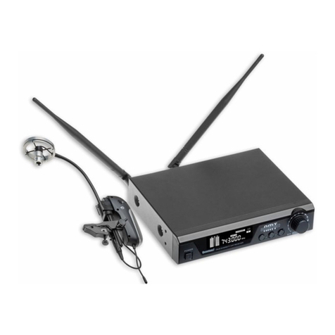
AMT Quantum 7 User manual

AMT Tech Support
104 Hillside Road
Sparta, NJ 07871
Ph: 973-222-1865
AMT Limited Warranty. Duration of this warrantee will remain in effect for one year from the date of the original purchase.
This warranty may be enforced by the original dated sales receipt or other proof of warranty coverage is presented when warranty
service is required.
What is covered? Except as specified below, this warranty covers all defects in materials and workmanship in this product. The
following are not covered by the warranty:
1. Damage resulting from accident, misuse, abuse or neglect.
2. Failure to follow instructions included with microphone.
3. Repair or attempted repair by anyone not authorized by A.M.T.
4. Failure to remove battery when storing.
5. Cause other than product defects including: lack of skill, competence, or experience of use.
6. Damages occurring during any shipment of this product (claims must be presented to carrier).
7. Damage to any unit which has been altered, or which the serial number has been defaced, modified, or removed.
AMT will pay all labor and material expense for covered items. Shipping charges are discussed later in this warranty. If your unit
needs service, please write or telephone us and we will advise you where the unit should be taken or sent. If you write us, include
your name, complete address, daytime telephone number, and a description of the problem.
DO NOT RETURN YOUR UNIT TO AMT WITHOUT A REPAIR AUTHORIZATION NUMBER.
If it is necessary to ship the product for service:
1. You must pay initial shipping charges, but if necessary repairs are covered by the warrantee, AMT will cover the return
shipping charges via carrier of AMT's choice to any destination within the United States.
2. Whenever warranty service is required a copy of the original dated sales receipt must be presented.
3. For products purchased outside of the USA, please contact 973-222-1865 for information pertaining to your country.
Exclusion of certain damages: AMT's liability for any defective product is limited to repair of replacement of the product of our
option. AMT shall not be liable for damages based upon inconvenience, loss of use of the product, loss of time, interrupted
operation, commercial loss; or any other damages whether incidental, consequential, or otherwise. Some states do not allow
limitations an implied warrantee lasts, and/or do not allow the exclusion or limitations of incidental or consequential damages, so the
above limitations may not apply to you. This warrantee is not enforceable outside of North America. This warrantee gives you
specific legal rights, and you may also have other rights, which vary from state to state.
For International Customers (Outside of the United States):
If the product is purchased inside of the United States and taken to another country, it is the responsibility of the product owner to
cover all shipping, customs, and duty if a warranty, upgrades, and repair issue is necessary. All provisions of the warranty above
apply except for Shipping and all costs related to shipping. Ie Customs charges and V.A.T. are not covered by AMT. All outside
charges associated with re-entry of the product into the USA is the sole responsibility of the product owner. At no time shall a
distributor or a dealer take it upon them selves to replace a defective system with a new system. This can only be done with the
permission of AMT’s tech support (973-222-1865) directly or through a distributor of the country purchased with AMT tech support
approval.
Repairs:
1) The customer, dealer, or distributor should contact AMT tech support via phone (973-222-1865 E.S.T. 12pm - 12am) or email with
a short description of the problem. Use the RETURN REPAIR form to send products for repair.
2) If out of warranty, we then advise the customer to call by phone to our tech support 1-973-222-1865 for a return authorization and
to discuss possible solutions before sending.
3) Date and origin of purchase required for warranty repair. If the product is covered under warranty, the product must ship back to
AMT, when completed, AMT will ship it back with the distributor’s next order.

Under warranty regulations, if a product has been damaged from miss-use such as:
Damage resulting from accident, misuse, abuse or neglect.
Failure to follow instructions included with microphone.
Repair or attempted repair by anyone not authorized by A.M.T.
Failure to remove battery when storing.
Cause other than product defects including: lack of skill, competence, or experience of use.
Damages occurring during any shipment of this product (claims must be presented to carrier).
Damage to any unit which has been altered, or which the serial number has been defaced, modified, or removed.
4) Most common problems found to be are over stressed goosenecks, broken cables, and plugs that have been crushed or bent.
These problems are NOT covered under warranty BUT in certain cases, if the shipping is taken care of both ways, we will repair it for
free. Due to this unique product, which is specialized in the audio field, most components that make up this product are proprietary.
In most cases, the entire product must be taken apart to its manufacturing stage in order to rebuild or replace damaged components.
This makes it almost impossible to use outside of the USA repair stations.
Thank you for choosing our wireless system, In order to obtain the best efficiency from the
system, you are recommended to read this instruction manual carefully.
Table of Contents
System Components…
Receiver Features…………………………………………
Transmitter Features………
System Setup…
Specifications…
System Components
All wireless systems include:
. True diversity receiver
. 6.35mm audio cable
. 2* BNC antennas
. Power supply
. User guide

Vocalist systems include:
. Handheld microphone
(Optional choices)
Body-pack systems include:
. Body-pack transmitter
Acoustic instrument clip-on systems include:
. Microphone transmitter with Ta3 connector.
. AMT microphone depending on package ordered.
. Built-in clip (located on transmitter) to secure to AMT microphones.
System Features:
UHF 600-952MHz frequency range (region dependant)
True diversity for maximum range and dropout protection
PLL Synthesized circuit
Pre-set 100 (10*10) selectable frequencies (bandwidth dependant)
IR sync downloading the frequency from receiver
LCD display shows status of frequency, AF and RF signal etc
EIA standard 1/2U rack-mountable metal chassis
Up to 500 feet(150m) line-of-sight operating range
Designed for vocalist and musical instrument applications
Receiver Features:
Front Panel
1. Power switch
Tap to turn on / tap to turn off. A blue light will illuminate when receiver turns on.
2. LCD display
The 63mm*22mm high resolution LCD display shows the group, channel, frequency, antenna
status, AF & RF level, and IR set.
3. IR (Infrared) port
Send IR signal to transmitter for synchronization
4. UP button
Adjust the frequency, channel, and group incrementally.
5. SET button
Menu control to set group, channel, frequency, IR Sync

6. DOWN button
Adjust the frequency, channel, group incrementally.
7. Volume control
Adjust the volume level. Volume knob outlined by blue light.
Back Panel
8. Power supply jack (DC12-18V / 500mA)
Connecting the power supply unit
9. 6.35mm (1/4”) unbalanced output jack
Connect the unbalanced input, e.g. of mixer or amplifier
10. Balanced XLR output jack
Connect the unbalanced input, e.g. of mixer or amplifier
11. TNC antennas sockets
Connect the high gain antennas
Transmitter Features:
Handheld Transmitter Option

1. Microphone head with cartridge inside
2. Metal pipe (Aluminum alloy)
Anodize any different colors, never fade.
3. Backlit LCD
Display group, channel, frequency and battery life.
4. IR infrared port
Receiver infrared beam to synchronize frequencies, hold the transmitter with its IR port facing
directly towards the receiver’s IR port with a distance between 5-20cm.
Note: When using multiple systems, only one transmitter IR port should be sync’d at a time.
5. ON/OFF and Mute switch
Push up the switch to turn on, Mute at the mid position.
6. Battery compartment
To replace batteries, unscrew the bottom pipe part counter-clockwise, make sure to put the
battery in the right polar directions.
7. Caps-on (three different choices)
Body-pack Transmitter

1. Antenna
1/4 wave length wire type antenna, it should be fully extended during normal operations
2. Backlit LCD
Displays frequency and battery life, if the battery symbol blinks, the battery needs to be replaced
immediately.
3. UP button
Adjust the frequency, incrementally
4. SET button
Menu control to set frequency
5. DOWN button
Adjust the frequency incrementally
6. IR infrared port
Receiver infrared beam to synchronize frequencies, hold the transmitter with its IR port facing
directly towards the receiver’s IR port with a distance between 5-20cm.
Note: When using multiple systems, only one transmitter IR port should be expose at a time.
7. Battery compartment
To replace batteries, slightly press the marked positions on left and right side of the cover and
open forward, make sure to put the battery in the right polar directions.
8. Input
4-pin mini XLR input for supplier microphone, guitar cable or other musical instrument
microphones (Saxophone, violin, viola, cello, acoustic guitar etc)
9. Volume control
Clockwise to increase volume, counter-clockwise to reduce volume.
10. Light touch power switch
Tap to turn on, long press (2 seconds) to turn off.

11. Belt-clip
Clip to the belt or guitar strap
Acoustic Instrument Transmitter:
1. Each AMT microphone has a disconnect. (D.C.T.) Connect the cable from the Q7 Transmitter
to the 3pin (Ta3) input connector on the microphone.
2. Adjustable Gooseneck
Adjustable at angle to allow sound to escape from instrument and develop naturally.
3. Mounting Screw
To REINFORCE the transmitter’s stability on the bell of saxophone / horn, rubber protection
avoids damage of the instrument.
4. BATT/PO
Power and battery LED, the blue LED remains lit as long as the transmitter has power; if the
blue LED is flashing, the battery need to be replaced immediately.
5. Mute Button
6. Light touch power switch
Tap to turn on, long press (2 seconds) to turn off.
7. Antenna
1/4 wave-length wire type antenna, MUST be fully connected and extended during normal
operations. Reception will be poor without antennas connected.
8. IR infrared port
Receiver infrared beam to synchronize frequencies, hold the transmitter with its IR port
facing directly towards the receiver’s IR port with a distance between 5-20cm.
9. Battery compartment
Insert a standard AA alkaline battery here, make sure to put the battery in the right polar
directions.
10. Battery cover
Pull back gently on this cover at the ribbing and pry upwards to remove
System Setup
1. Connect the included AC power supply to the rear of the receiver and turn on the receiver.

2. Standard Display
The standard display shows the preselected group and channel.
Group
Push the SET button and hold for 1 second, the GROUP icon will blink. Push the up and down
buttons to set the desired group (01-10), Press SET again to confirm.
The display will return to the standard operating setting after a short period of non-activity
automatically.
NOTE: Each group 01-10 consists of 10 channels, each corresponding to a specific frequency.
Some frequency bands, for specific regions, will not have 10 channels per group. (Groups vary by
region.)
Channel
After setting the group, press SET again, the CHANNEL will blink. Push the up and down buttons
to set the desired channel (01-10 region dependent) Press SET again to confirm.
The display will return to the standard operating appearance after a short period of non-activity
automatically.
IR Sync
After setting channel, press the SET again, the IR Icon will blink (picture 1). Push the SET button
and hold for 1 second, the receiver will start to send the infrared signals (picture 2), then put the
transmitter (handheld, body-pack or musical instrument) IR port close to the receiver’s IR port.
The transmitter has to be synchronized to the same frequency (group and channel) before using.
After a successful sync, the display RF signal and Antenna icon appears. (Picture 3)

Transmitter / Receiver IR Quick Sync
With the receiver in normal operating mode, and the TRANSMITTER OFF, push and hold the SET
button on the receiver to sync the transmitter to the receiver. While the receiver is sending the signal,
turn the transmitter ON. If, for some reason, your transmitter is not on the same channel from the last
usage, you can use the IR Quick Sync method to quickly sync the transmitter without having to page
through the group and channel setting functions.
Transmitter Sync’ing
When sync’ing the transmitter, it is best to power the transmitter OFF first, then power the
transmitter on while your sending the sync from the receiver. This procedure will re-set the
transmitter, allowing for it to sync to the newly selected channel before it locks / syncs to a
channel on the receiver.
Specifications:
Receiver
Frequency Preparation:PLL Synthesized Control
Frequency Range:600-952MHz(Region dependent)
Frequency Type:F3E
Modulation Type:FM
Channels: 100(10x10)
Oscillation System:VCO
Type of reception:True Diversity
Receive Sensitivity:-11dBm (sinad≥30dB)
Frequency Response:60Hz-17KHz+/-3dB
S/N Ratio: ≥105dB
T.H.D:<0.5% at 1KHz
Dynamic Range:>100dB
Operating Temperature: -10-+50℃
Display: Backlit LCD (63mm*22mm)
Audio Output:1*Balanced XLR Socket 1*6.35mm Jack
Antenna: 2*BNC
Power Supply:DC12V-18V/500mA
Dimensions( L*W*H): 210*170*44mm

Handheld Transmitter
Frequency Preparation:PLL Synthesized Control
Frequency Range:600-952MHz(Region dependent)
Frequency Deviation:±48KHz
Microphone Type:Dynamic
Polar Pattern:Cardioid
RF Output Power:10mW
Controls:ON/MUTE/OFF
Indicators:Backlit LCD
Interface:Infrared
Power Supply: 2*AA battery
Operating Voltage:3V
Operating time: 10h (depending on batteries)
Dimensions:265mm
Body-pack Transmitter
Frequency Preparation:PLL Synthesized Control
Frequency Range:600-952MHz(Region dependent)
Frequency Deviation:±48KHz
Input:3 pin mini-XLR
RF Output Power:10mW
Controls:Power ON//OFF, Volume, SET frequency
Indicators:LED (AF)
Interface:Infrared
Antenna: 1/4 wave Length Wire Type
Power Supply: 2*AA battery
Operating Voltage:3V
Operating time: 10h (depending on batteries)
Dimensions( L*W*H):110*63*21mm
Acoustic Instrument Transmitter
Frequency Preparation:PLL Synthesized Control
Frequency Range:600-952MHz(Region dependent)
Microphone Type: Condenser
Frequency Deviation:±48KHz
RF Output Power:10mW
Controls: ON/OFF, MUTE
Indicators:LED(PO/BATT)
Interface:Infrared
Antenna: 1/4 wave Length Wire Type
Power Supply: 1*AA battery

Operating Voltage:1.2-1.5V
Operating time: 10h (depending on batteries)
Dimensions: 115*25*62mm
FCC CE1622 ROHS ….
Table of contents
Other AMT Microphone System manuals