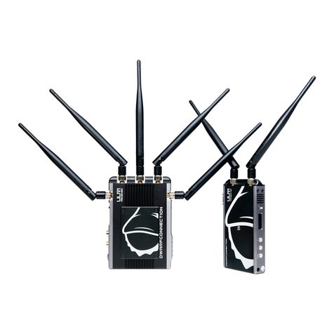
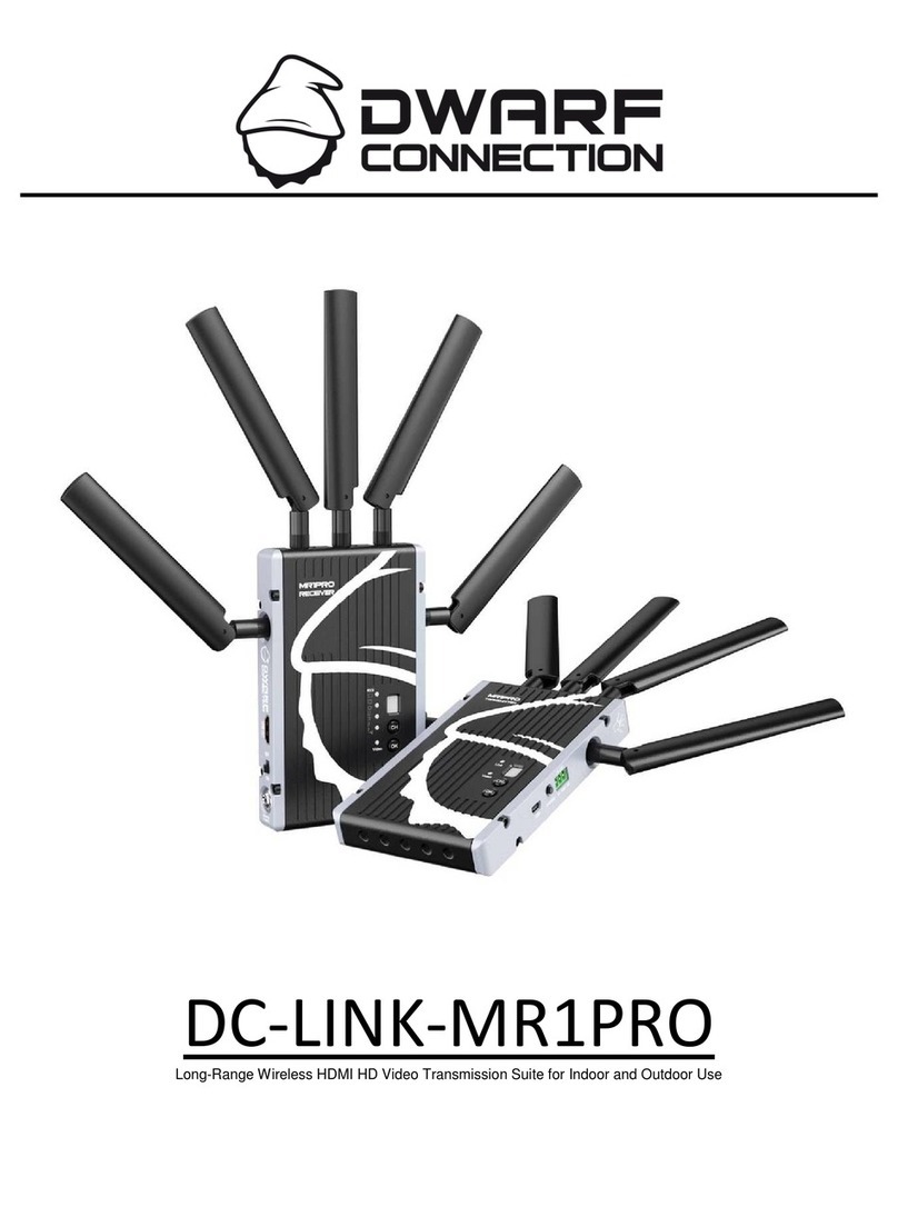
Dwarf Connection DC-Link-LR1 User manual

DC-LINK-LR1
Long Range Wireless HDMI/SDI HD Video Transmission Suite for Indoor use
Manual / Handbuch

Introduction
Congratulations on purchasing the DC-Link-LR1 Video Transmission System. Please
read this manual carefully before operating your product, and ensure it is kept in a
safe place.
The technology contained in this product, including the device itself as well as
related software and trademarks, is protected by law. Any duplication or
reproduction without the written permission of the copyright owner is prohibited, in
part or in full. All third-party brands or copyrights mentioned in this manual are the
property of their respective owners.
This product has a limited warranty of one year. Warranty may be voided by:
!Physical damage to the product
!Any damage caused by improper use, maintenance or storage
!Damage resulting from the use of incorrect power supplies
!Damage not related to the design of the product or the quality of its
manufacture
2

Safety Precautions
The Video Transmission System
Do not block or obstruct air vents, as this may cause short circuits, fire or electric
shocks. Turn the device off immediately if it comes into contact with liquids.
The Power Supply
The device may be used with batteries or AC-DC power supplies of the voltage
specified on the device or in the enclosed documentation.
If batteries are used, please ensure that the batteries are compatible and have no
cracks or leaks.
Please use the enclosed power adapter. When using a third-party power adapter,
please ensure that the adapter conforms to the specifications of the device and has
the correct polarity.
Remove the power supply if:
-The device will not be used for an extended period of time
-The power cable is damaged
-The exterior of the device is damaged.
Operating Environments
-Due to current regulations governing the use of radio-based systems, this
device is authorised for indoor use with the pre-installed channels five and six
(by law, “indoor use” is defined as use in a building including places
assimilated thereto in which the shielding will typically provide the necessary
attenuation).
-Do not place the device on metallic surfaces, to ensure effective data transfer.
-Do not place the device on dirty or damp surfaces.
-Do not use the device in the proximity of water or in high humidity, near open
fires or gas pipes, or near electrical mains.
3
ENGLISH

Overview
The DC-Link-LR1 is a high-performance WHDI video transmission system which
transmits uncompressed video and audio signals up to 700m with low latency
(1 ms delay).
Due to the conscious decision not to implement the DFS (Dynamic Frequency
Selection) System, which is compulsory for outdoor use, the device has a longer
range, greater stability and better usability than comparable systems, but is only
authorised for indoor use.
Transmitter and receiver both have 3G-HD-SDI and HDMI connectors (Plug & Play).
When a video source is attached, the transmitter automatically selects the input (SDI
is prioritised). The receiver’s 3G-HD-SDI and HDMI outputs may be used
simultaneously.
Four receivers may be used for every transmitter.
The DC-Link-LR1 Video Transmission System is compatible with the DC-Link-CLR1
Video Transmission System.
4

Characteristics
!700m Range
Transmission ranges of up to 700m are possible with good line-of-sight and optimum
antenna positioning
!Rapid and Reliable Connectivity
The decision not to implement the DFS System compulsory for outdoor use, as well as the
preinstalled transmission channels, mean there is no need for complex pairing procedures. In
addition, transmission stability is increased
!Real-Time Transmission
With a latency of less than 1ms, the system is suitable for live monitoring applications
!Uncompressed Transmission
10-bit, 4:2:2 transmissions via 3G-SDI and HDMI without format conversion
!Supports Formats up to and including 1080p 60Hz
!2- Channel Audio Transmission
Embedded audio transmission on CH1 & CH2 via SDI and HDMI, incl. formats such as Dolby
TrueHD, DTS-Master etc.
!License-free Frequency Band
Functions in the license-free 5GHz ISM frequency range from 5.1-5.9GHz
!Multicast Support
1:1 or 1:n transmissions with up to four parallel systems
!Metadata- and Timecode Transmission
!AES-128 Encryption
!Metal Casing
Transmitter and receiver are extremely durable
!Variable Input Voltage
Input voltage range from 6.5-16.8V DC allows the system to be operated with a variety of
batteries or power supplies
!Status Displays
Status displays for DC power, video and RSSI signal strength
!Mount
1/4" tripod mount
!Battery Adapter Plate
Delivered with NPF/V-Mount battery plates as standard
!Plug-and-Play Design
Ready to use without the need for complex configuration
!1 Year Manufacturer’s Guarantee
5
ENGLISH

Product Description
Transmitter:
1) ¼“ Tripod Mount
2) Antenna Connection: RP-SMA (male) Connector
3) Video Status Display: Yellow LED
4) Power Status Display: Green LED
5) Frequency Selector: 10 Channels at Positions 0-9
(Channels 5&6 permitted in Europe)
6) SDI-IN: 3G/HD/SD-SDI Input, (BNC Female Connector)
7) HDMI-IN: HDMI Input (Type A Female Connector)
8) ON-OFF: Power Switch
9) DC-IN: 6.5 – 16.8V DC
6

Product Description
Receiver:
1) ¼“ Tripod Mount
2) Antenna Connection: RP-SMA (male) Connector
3) RSSI Status Display: Signal Strength (5 Green LEDs)
4) Video Status Display: Yellow LED
5) Power Status Display: Green LED
6) Frequency Selector: 10 Channels at Positions 0-9
(Channels 5&6 permitted in Europe)
7) SDI-IN: 3G/HD/SD-SDI Input, (BNC Female Connector)
8) HDMI-IN: HDMI Input (Type A Female Connector)
9) ON-OFF: Power Switch
10) DC-IN: 6.5 – 16.8V DC
7
ENGLISH

Operation
Transmitter
1. Connect the two omni-directional antennas to the RP-SMA male connectors.
2. There is a ¼“ tripod mount at the base of the transmitter if required.
3. Use the enclosed 4-pin male-to-D-TAP cable to connect to a power supply with a
suitable voltage.
4. In order to comply with local laws, please ensure you select the appropriate
frequency for your country (more information on page 10).!
Receiver
1. There is a ¼“ tripod mount at the base of the receiver if required.
2. Use the enclosed 4-pin male-to-D-TAP cable to connect to a power supply with a
suitable voltage.
3. Ensure you have selected the frequency that corresponds to that of the
transmitter.
Signal Distribution
Connect the camera’s SDI or HDMI output to the transmitter’s SDI or HDMI input. If
both SDI and HDMI inputs are active, the transmitter will prioritise the SDI signal.
Connect the receiver’s SDI or HDMI output to the SDI or HDMI input of the
monitoring/recording device. During active transmission, both the SDI and the HDMI
output on the receiver may be used simultaneously.
Ensure that the antennas are connected firmly, that all other connections are stable,
and that the batteries are suitable.
8

Operation
Antenna Positioning
Position the antennas on transmitter and receiver at right angles as shown in the
illustration. This ensures the best possible RF performance.
Install the transmitter and the receiver as high as possible (at least 1.5 metres above
ground level), to maintain a good line-of-sight. During operation, try to keep the
transmitter and the receiver at similar heights.
Avoid obstacles such as walls, trees, water and steel structures between transmitter
and receiver as much as possible.
The connection is at its strongest when the flat surfaces of the transmitter and
receiver face each other (see illustration).
9
ENGLISH

Operation
Choosing a Frequency
The system functions with 10 channels in the license-free 5 GHz ISM frequency band.
Both the transmitter and the receiver have a frequency
selector with positions from 0-9. Only channels 5 & 6
are permitted for use within Europe.
Both the transmitter and the receiver have to be set to
the same channel in order to communicate with each other. If several systems are
used at once, then the channels used should be as far from each other as possible to
avoid interference or a reduction in range. A maximum number of 4 systems
simultaneously is recommended.
Authorised Channels by Country (Selection)
Please ensure you are aware of the local regulations regarding radio frequencies in
the relevant country before operating the system.
Position
(Channel)
Frequency
Europe
U.S.A.
Canada
Russia
Japan
China
Turkey
0
5550 MHz
x
x
x
✓
x
x
x
1
5590 MHz
x
x
x
✓
x
x
x
2
5630 MHz
x
x
x
✓
x
x
x
3
5670 MHz
x
x
x
✓
x
x
x
4
5150 MHz
x
x
x
✓
x
x
x
5
5190 MHz
Indoor
Indoor
Indoor
✓
Indoor
✓
Indoor
6
5230 MHz
Indoor
Indoor
Indoor
✓
Indoor
✓
Indoor
7
5270 MHz
x
x
x
✓
x
x
Indoor
8
5310 MHz
x
x
x
✓
x
x
Indoor
9
5510 MHz
x
x
x
✓
x
x
x
10

Operation
RSSI Display
The RSSI (Wireless Received Signal Strength Indicator) display shows the strength
of the signal, allowing the operator to ensure the system is working reliably.
Display
Status
Description
RSSI
0-1 LEDs
Radio signal strength is weak and artefacts are visible in the
video signal
2-3 LEDs
Radio signal strength is normal and video quality is good
4-5 LEDs
Radio signal strength is very strong and video quality is very
good
11
ENGLISH

Operation
Establishing a Connection
Once all previous steps have been performed, turn on the transmitter and the receiver
using the power switch. The “Power” LED lights up.
Once the transmitter recognises a video input, the “Video” LED lights up.
!
It takes approximately 20-30 seconds for the transmitter to connect to the receiver.
During this brief period, the receiver’s video out displays “Link Connecting…”.
Once the connection is established the “RSSI” and “Video” LEDs on the receiver light
up. The OSD disappears and the system is operational.
Display
Status
Description
Power
continuous
Power is connected, device is on
off
Power is disconnected, or the device is turned off
Video
continuous
Video connected to input, video format has been
recognised
off
Video input is inactive or the video format is not
recognised
12

Transmission Information
The system’s maximum possible range is dependent on each location’s operating
conditions. The stated range of 700 metres cannot always be guaranteed.
Transmission takes place in a non-exclusive bandwidth. As a result, interference from
other devices operating in the 5GHz bandwidth may occur occasionally.
Transmission range may be affected by construction methods or materials used in
surrounding buildings. Environmental conditions such as humidity and the physical
surroundings may have an effect on transmission, irrespective of the transmitter or
receiver.
The strength of the signal is also dependent on the correct positioning of the
antennas, as well as the location, height and angle of the transmitter and the receiver
to each other. If you are unable to achieve a stable transmission, try changing these
factors or choose a different frequency.
Due to the conscious decision not to implement the DFS System required for outdoor
use, the use of this system may impact other radio systems such as air traffic control
or weather radar systems. DwarfConnection hereby declares that it has informed
purchasers of this system of its legal and appropriate use within the guidelines of the
European Telecommunications Standards Institute (ETSI), and assumes no
responsibility for any consequences resulting from inappropriate use of these devices.
13
ENGLISH

Maintenance
Please do not attempt to repair, modify or alter these devices under any
circumstances.
Clean the devices with a soft, clean, dry and lint-free cloth. Do not open the devices,
they contain no user-serviceable parts.
Storage
The devices can be stored at temperatures between -20°C and 60°C. For long-term
storage, please use the original transport case and avoid environmental conditions
such as high humidity, dust, or excessively acidic or base surroundings.
Warning!
To ensure your own safety, please use only high-quality brand name
batteries, and follow the safety information and instructions provided by
the manufacturer.
14

Troubleshooting
Possible Cause
Possible Solution
No video output
Lack of power
Check power supplies of transmitter and
receiver and ensure that all cables are
connected correctly and that there is sufficient
power
Antennas
Ensure antennas are not damaged and are
firmly connected
Video connection cable
Examine the transmitter’s “Video” LED display.
If the LED is dark, check the HDMI or SDI
connection cable
Frequency selection
Ensure that the transmitter and receiver are set
to the same channel
Unsupported video
format
Check your selected video format agains the
product’s technical specifications
Inadequate
video quality
Connections
Check to ensure that all SDI or HDMI cables are
firmly connected
Range is too great or
signal is obstructed
Check how many “RSSI” LEDs are lit on the
receiver. For decent quality, at least 2-3 LEDS
should be lit. If only one is lit, the signal is weak
and the distance between transmitter and
receiver should be reduced. Alternatively,
obstacles between the devices should be
removed or another channel selected
Radio signal is
experiencing
interference
Wait one minute then restart transmitter and
receiver or change the frequency channel
15
ENGLISH

Technical Specifications
Transmitter
Receiver
Connections
1x SDI Input (BNC female)
1x HDMI Input (Type A female)
2x Antenna (RP-SMA male)
1x DC Input (4-pin female)
1x SDI Output (BNC female)
1x HDMI Output (Type A
female)
5x Antenna (RP-SMA male)
1x DC Input (4-pin female)
Power
6.5 – 16.8V DC
6.5 – 16.8V DC
Power Consumption
< 6 W
< 7 W
Dimensions (LxBxH), w/o
Antennas
120 x 70 x 25mm
160 x 110 x 25mm
Weight
380g
540g
Supported Video Formats
1080p(60, 59.94, 50, 30,
29.97, 25, 24, 23.98)!
1080i (60, 59.94, 50)!
720p (60, 59.94, 50)!
576i (50)!
480i (59,94)
1080p(60, 59.94, 50, 30,
29.97, 25, 24, 23.98)!
1080i (60, 59.94, 50)!
720p (60, 59.94, 50)!
576i (50)!
480i (59,94)
Audio Format
SDI Embedded 2 Channel
Audio 24bit/48kHz
SDI Embedded 2 Channel
Audio 24bit/48kHz
Displays
POWER – Green
VIDEO – Yellow
Power – Green
VIDEO – Yellow
Wireless RSSI – Green (5
LEDs)
Frequency Range
5.1 – 5.9 GHz ISM Band
Modulation Process
OFDM 16 QAM
OFDM 16 QAM
Transmitting Power
max 21 dBm
-
Receiver Sensitivity
-
- 75 dBm
Bandwidth
40MHz
40MHz
Operating Temperature
0 – 40°C (Operation)
-20 – 60°C (Storage)
0 – 40°C (Operation)
-20 – 60°C (Storage )
Certification
FCC, CE
FCC, CE
16

Included with Purchase
1x Transmitter !
1x Receiver!
8x External Antennas (can be ordered individually)!
2x DC Adapter Cables from Anton Bauer (D-Tap) (m) to 4-pin DC Connector(m)!
2x Power Supplies
1x Pro Clamp!
1x Magic-Arm with 1/4" Screw
1x Hot Shoe Adapter
2x Slot Screwdriver
1x Quickstart Manual (English/Deutsch)
1x Transport Case
17
ENGLISH

Notes
Vorwort
18

Vorwort
Herzlichen Glückwunsch zum Kauf des DC-Link-LR1 Indoor Videofunksystems.
Bitte lesen Sie sich das Handbuch aufmerksam durch, bevor Sie das Gerät in
Betrieb nehmen und bewahren Sie es sorgfältig auf.
Die in diesem Produkt verbaute Technologie ist rechtlich geschützt, inbegriffen
Gerät, Software und Markenzeichen. Eine Vervielfältigung ohne die vorherige
schriftliche Genehmigung des Urheberrechtsinhabers ist weder auszugsweise noch
insgesamt gestattet. Alle in diesem Handbuch genannten und ggf. durch Dritte
geschützten Marken- und Warenzeichen sind das Eigentum des jeweiligen Besitzers.
Die Garantiezeit für dieses Produkt beträgt 1 Jahr, ausgeschlossen sind:
!Physikalische Beschädigung des Produktes
!Jegliche Beschädigung oder Zerstörung hervorgerufen durch unsachgemäße
Benutzung, Wartung oder Lagerung
!Eine Beschädigung des Produktes hervorgerufen durch Verwendung einer
falschen Spannungsversorgung
!Eine Beschädigung des Produktes, nicht zurückzuführen auf das Produktdesign
oder die Verarbeitungsqualität
Öffnen Sie das Gerät nicht, es enthält keine durch den Anwender zu wartenden
Teile. Im Fehlerfall schicken Sie das Gerät an den Service. Jeder andere Einsatz, als
der in dieser Bedienungsanleitung beschriebene, ist nicht bestimmungsgemäß und
führt zu Garantie- und Haftungsausschluss.
Für Anregungen oder Fragen zu diesem Produkt kontaktieren Sie uns bitte per
Email.
19
DEUTSCH

Sicherheitshinweis
Der Videofunk
Blockieren und verstopfen Sie niemals die Lüftungsschlitze des Gerätes, andernfalls
kann es zu Kurzschluss, Feuer oder elektrischem Schock kommen.
Schalten Sie das Gerät sofort aus, wenn es mit Flüssigkeiten in Kontakt kommt.
Die Spannungsversorgung
Das Gerät kann mit Akkus oder einem AC-DC Netzgerät im gerätespezifischen
Spannungsbereich betrieben werden.
Falls das Gerät mit Akku betrieben wird, vergewissern Sie sich dass der Akku
kompatibel ist und dieser fest verriegelt ist.
Verwenden Sie den beigelegten Spannungsadapter. Bei Verwendung eines
Netzgerätes eines Drittanbieters vergewissern Sie sich, dass der Spannungsbereich
des Netzgerätes sich in den gerätespezifischen Grenzen befindet und die Polarität
korrekt ist.
Trennen Sie die Spannungsversorgung unter folgenden Umständen:
-Wenn Sie das Gerät für einen längeren Zeitraum nicht benutzen
-Wenn das Stromkabel beschädigt ist
-Wenn das Gehäuse des Produktes beschädigt ist
Die Betriebsumgebung
-Auf Grund der geltenden Funklizenz Vorschriften ist dieses System nur für die
Anwendung in Innenräumen und unter Verwendung der voreingestellten
Kanäle fünf und sechs, zugelassen (per Definition gilt eine bauliche Substanz,
die nach außen einem Gebäude ähnliche Dämpfungswerte aufweist als
Innenraum)
-Stellen Sie das Gerät nicht auf metallische Gegenstände, damit eine effektive
Datenübertragung gewährleistet werden kann
-Stellen Sie das Gerät nicht auf einen verschmutzen oder feuchten Untergrund
-Betreiben Sie den Videofunk nicht in der Nähe von Wasser oder bei hoher
Luftfeuchtigkeit, in der Nähe von offenem Feuer oder Gasleitungen und nahe
spannungsführenden Leitungen
20
Table of contents
Languages:
Other Dwarf Connection Microphone System manuals
Popular Microphone System manuals by other brands

Polymap Wireless
Polymap Wireless Polytel user manual

Listen Technologies
Listen Technologies LA-123 90 Design guide

Simpleway
Simpleway nnounce micnode aux Hardware user's guide

Lectrosonics
Lectrosonics SMWB series instruction manual

Samson
Samson Airline 88 owner's manual

Eaton
Eaton TRSM0020 Service manual

Audio Technica
Audio Technica 1600 Series Installation and operation guide

Sennheiser
Sennheiser EW 322 G3 datasheet

Shure
Shure BLX Wireless System user guide

Gemini
Gemini Professional UHF Wireless System UX-16 H Features

Nissindo
Nissindo LX-2020 G2 Operation manual

Audio Technica
Audio Technica ATW-901a/L Installation and operation manual