For full warranty information, refer to the AMX Instruction Manual(s) associated with your Product(s).
6/08
©2008 AMX. All rights reserved. AMX and the AMX logo are registered trademarks of AMX.
AMX reserves the right to alter specifications without notice at any time.
3000 RESEARCH DRIVE, RICHARDSON, TX 75082 • 800.222.0193 • fax 469.624.7153 • technical support 800.932.6993 • www.amx.com
93-1600-01 REV: C
Connecting the RF Input
Connect the RF feed from your cable or satellite provider to the RF Input connector
on the rear panel.
• The coaxial RF feed that is delivered from your cable provider or satellite
headend must be terminated to a male F Type connector (FIG. 4).
• The signal level must be between +20 dbmV and +40 dbmV with no more than
a 6db variation between channels.
Network Configuration
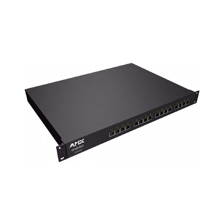
1. Connect the supplied serial console cable (RJ12-DB9) from a laptop/desktop
to the serial connector on the TVM-1600.
2. Open a console session (Hyperterminal, Terminal, etc.) with default terminal
settings as follows:
• Baud Rate = 9600 bits per second
• Data Bits = 8
• Parity = None
•StopBits=1
• Flow Control = None
3. Start the terminal session and enter the administrator password "admin" when
prompted.
4. Configure the TVM-1600's TCP/IP address.
Note: The TVM-1600 does not support DHCP so you must configure a static IP
Address.
5. i [return] will display the current default TCP/IP address i.e. 192.168.0.96
6. To set the TVM-1600's TCP/IP Address type:
i xxx.xxx.xxx.xxx where xxx.xxx.xxx.xxx is the new IP address of this unit.
For example i 192.168.0.100 [return], to set the IP address as 192.168.0.100.
7. To set the Network Subnet Mask type: is xxx.xxx.xxx.xxx.
For example is 255.255.255.0 [return].
8. To set the Default Gateway type: ig xxx.xxx.xxx.xxx.
For example ig 192.168.0.1 [return].
Connecting to the TVM-1600
1. With the TCP/IP address configured, connect the TVM-1600 to your network
equipment (switch, hub) - or if required use the provided Ethernet Crossover
cable to connect your PC directly to the TVM-1600.
2. From a browser on your PC, browse to the newly defined IP address.
For example http://192.168.0.100.
3. You will be prompted for your admin password.
Note: Do not enter a username as this is the administrative login - but do type
in your password.
4. Once authenticated you will be presented with the on-board system
management web pages. Refer to the TVM Endeleo Browser Guide for details
of configuration but for now configure the system in the following order.
Setup
Perform the following for basic configuration from the Setup option. Click on the
Setup option.
1. Configure TCP/IP settings for Gateway/Subnet Mask and UTP Port if
required.
2. Define Hub Name if required. Click Update when complete.
Configuring Channel Names
Configure the Channel Names from the Channel Lineup Option. Click on Channel
Lineup.
1. Name each Channel with its appropriate call letters. For example CBS, ABC,
Bloomberg, etc.
2. Define the channel frequencies if required.
Each web page has 16 channels - to define a channel range choose the range
from the top of the page.
3. Define TV System Type:
• US version (FG-TVM-1600): This is set as "M" for standard US NTSC
frequencies and is preconfigured before shipment.
• UK version (FG-TVM-1600-PSC): this is set as “PAL I” for standard UK PAL
frequencies and is preconfigured before shipment.
4. Define your Max Channels - this is set at 128 by default. This setting should
remain at 128.
User Access
To configure which channels a port can receive, user access must be configured.
Click on the User Access option.
1. Grant each port access to channels by checking the appropriate box in the
grid. A green check means the port has access to that channel.
2. Each web page contains 16 channels to manage. To choose a different
channel range to configure click on the Channel range at the top of the
screen. For example click on 17-32 to manage channels 17-32 or click on
33-48 to manage channels 33-48.
Configuring Individual Ports
To configure ports for different channels or volume settings click on the Status
option. Ports can also be managed and controlled from the Status screen.
1. Name each individual port by clicking on the Port number - by default these are
Port 1 through Port 16. Ports can be named by location (Lobby TV) or by User
(John Doe).
2. Each port can be administered from the Status Page. The following
administration tasks can be performed.
• Change the channel by either number or name under the Channel Column.
• Adjust the Volume setting by number (from 0 - 63).
•Mute the volume on a given port by checking the Mute box.
•Lock the port to force that user/area to watch a specific channel at a specific
volume.
• Apply any of these changes by using the row at the top of the web page and
choosing the ports by checking the Included box next to the port. Then choose
either Channel Only, Volume Only or Execute All.
For instructions on the remaining Web Page options or a more detailed description of
the pages described above please refer to the TVM-1600 Operation/Reference
Guide.
Additional Documentation
Refer to the TVM-1600 Operation/Reference Guide (available online at
www.amx.com) for detailed information on configuring the TVM-1600 (including
(Devices, Port Control, and Messaging), TVM-RX03 receivers and source devices.
FIG. 4 RF Feed
FIG. 5 Setup
FIG. 6 Channel Names
FIG. 7 User Access
FIG. 8 Individual Ports
