Installation Guide
NXA-UPS1500 (120v/240v) Uninterruptible Power Supply
NXA-UPS1500 (120v/240v) UPS
The NXA-UPS1500 is a Uninterruptible Power Supply (UPS) featuring Double AVR Boost
and Double Buck, Pure Sine Wave Output, LCD Display and Hot-Swappable Battery. The
NXA-UPS1500 supports RS232 control. The NXA-UPS1500 is available in two voltages:
• 120V (FG678-15)
• 240V (FG678-20)
The NXA-UPS1500 features tower/rack-convertible design making it ideal for use with AMX’s
line of MAX devices (FIG. 1). IMPORTANT SAFETY INSTRUCTIONS
SAVE THESE INSTRUCTIONS: This manual contains important safety instructions. Please
follow all instructions carefully during installation. Read this manual thoroughly before
attempting to unpack, install or operate.
CAUTION - To prevent the risk of fire or electric shock, install in a temperature and humidity
controlled indoor area, free of conductive contaminants.
CAUTION - Risk of electric shock, do not remove the cover. No user serviceable parts. Refer
servicing to qualified service personnel.
CAUTION - Risk of electric shock, hazardous live parts inside this UPS can be energized
from the battery supply even when the input AC power is disconnected.
WARNING - This is a Class A-UPS Product. In a domestic environment, this product may
cause radio interference, in which case, the user may be required to take additional
measures.
NOTICE - The UPS is designed to be for use with computer loads only.
NOTICE- To prevent injury, do not carry with the handle of front cover when moving the UPS.
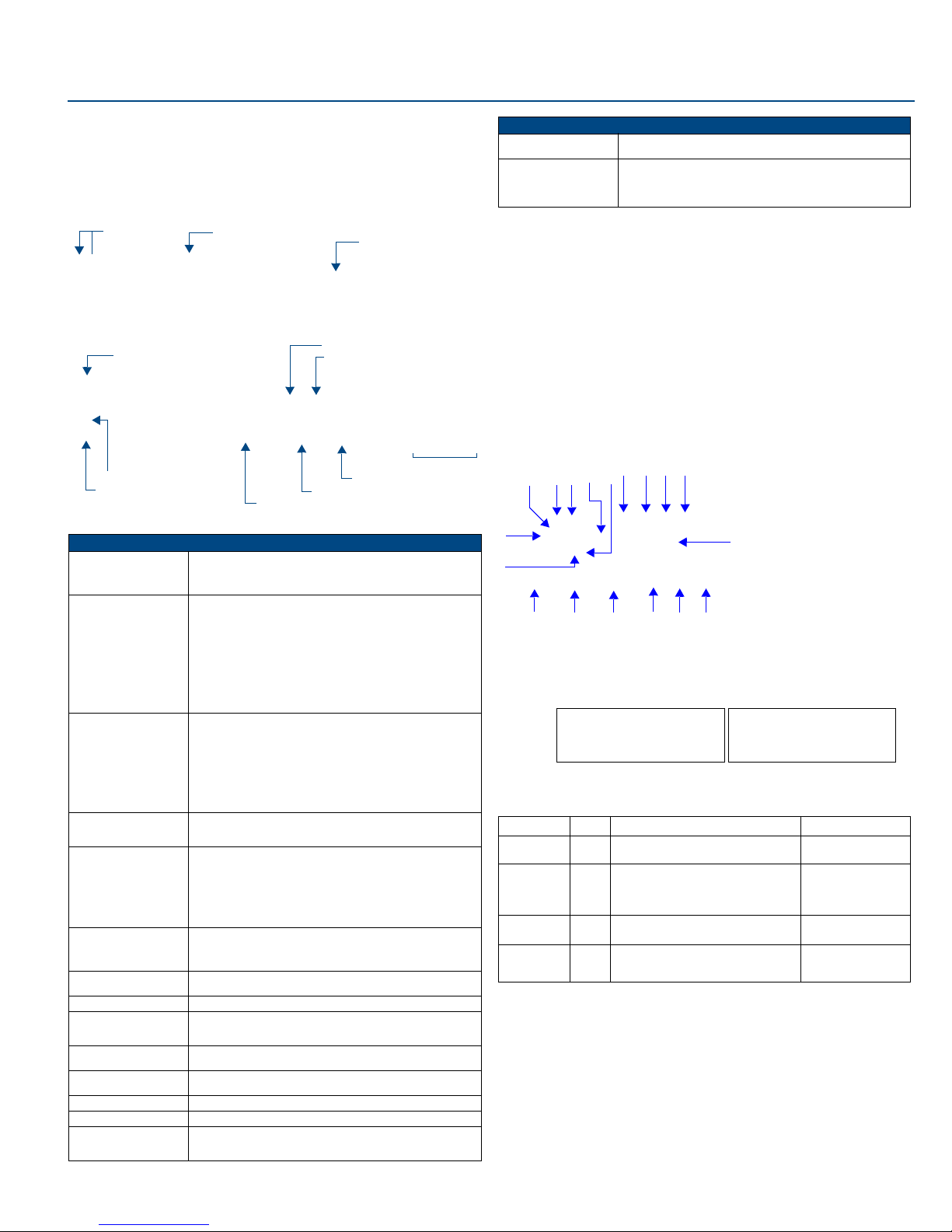
Front Panel LCD and LEDs
FIG. 2 describes the elements of the front panel LCD:
DIP Switch Setting
The nominal voltage of the UPS can be reset by the DIP Switch on the rear panel of the UPS.
The following charts describe the voltage settings.
Indicators & Alarms
Setup Instructions
Connecting the Batteries
The UPS1500 ships with the four batteries installed inside the unit. Before use, you will need
to connect the main power connector inside the unit:
1. Remove the Release tabs on the front panel (see FIG. 1) to expose the screws that
secure the Battery Compartment Cover.
2. Remove the screws beneath the Release tabs (FIG. 4).
3. Remove the Battery Compartment Cover to access the Battery Compartment.
4. Remove the screw holding the metal securing piece in place.
5. Slide the metal securing piece into the groove on the 4-pin connector (red) from the
battery cable harness.
6. Connect the 4-pin connector to the matching connector inside the unit.
7. Reattach the metal securing piece above the connector with the screw (FIG. 5).
FIG. 1 NXA-UPS1500 Uninterruptible Power Supply
NXA-UPS1500 Product Specifications
Input: • Voltage Window (DIP Switch selectable):
120V version (FG678-15): 110/115/120 Vac +35% ˜ -32%
240V version (FG678-20): 220/230/240 Vac +35% ˜ -32%
• Frequency: 45 ˜ 65Hz (50/60Hz auto-sensing)
Output: • Voltage Window (AC Mode):
120V version (FG678-15): 110/115/120 Vac +8% ˜ -12%
240V version (FG678-20): 220/230/240 Vac +8% ˜ -12%
• Voltage Window (INV Mode):
120V version (FG678-15): 110/115/120 Vac +/-5%
240V version (FG678-20): 220/230/240 Vac +/-5%
• Capacity (VA/W):1500/900
• Wave Form: Pure sine wave
• Frequency: 50Hz/60Hz +/-0.1Hz
• Transfer Time:2 ms typical
• Autonomy: > 8 min.
• DC Start: Yes
Battery: • Type: 12V, sealed lead acid maintenance-free
• Capacity: 9AH
• Quantity: 4 12V batteries required
• Voltage:
120V version (FG678-15): 24 Vdc
240V version (FG678-20): 48 Vdc
• Recharge Time: 2 ˜ 4 hours to 90%
• Storage: Store at -15 to +30 °C (+5 to +86 °F), charge the UPS
battery every 6 months / Store at +30 to +45 °C (+86 to +113 °F),
charge the UPS battery every 3 months.
LED indicators: • Utility mode
• Backup mode
• Battery conditions
Display LCD: • Load level (%)
• Battery level (%)
• Bypass
• AVR-Boost/AVR Buck
• Battery Low/Replace/Fault
• UPS Fault
• Site Wiring Fault
• Overload
Overload Protection: • AC Mode: >110% Buzzer continuously alarms, and shuts down in
10 minutes.
• Inverter Mode: >120% Buzzer continuously alarms, and shuts
down in 10 seconds.
Short Circuit Protection: • AC Mode: Breaker and electronic circuit
• Inverter Mode: Shut down automatically in 8 cycles
Self-Diagnostics: Upon Power-on
Alarms: • Line Failure
• Battery Low
• Overload and Fault
Operation Environment: • Temperature: 32° - 104°F (0-40° C)
• Operation Humidity: 95% RH Maximum, non-condensing
Dimensions (HWD): • 3.46” x 17.32” x 18.97” (8.80cm x 44.0cm x 48.2 cm)
• 2U rack height
Control Communication: RS-232
Weight (with batteries): 70.3 lbs (31.89 kg)
Certifications: • EN50091-1-1:1996 (Safety)
• FCC Part 15, Subpart B - Class A
• UL: YEDU.E166979
(front)
(rear)
Front Panel LCD
Battery Compartment
RS232 Communication Port
DIP Switch
USB Communication Port
RJ-45 Ports (Network Surge Protection)
Power Outlets
Output Breaker
Input Breaker
External Battery Terminal
Input Power Socket (Inlet)
Release tabs
NXA-UPS1500 Product Specifications (Cont.)
Included Accessories: • AC Input Power Cord
• Tower and rack-mounting accessories
Other AMX Equipment: NXA-UPS1500 EPM Extended Power Module (FG 678-16)
NXA-UPS1500ECJ, European Power Cable (FG 678-17)
NXA-UPS1500UKCJ, United Kingdom Power Cable (FG678-18)
NXA-UPS1500ACJ, Australian Power Cable (FG678-19)
FIG. 2 Front Panel LCD and LEDs
FIG. 3 DIP Switch Settings (sets nominal voltage)
Indicator Color Description Alarm
Utility Mode Green • Steady: Output Load is supplied by Utility.
•Blinking: Polarity error or Ground Fault.
None
Backup Mode Amber •Steady (with alarm): Output Load is
supplied by Battery.
•Blinking every 5 seconds (no alarm):
Stand by for Utility recovery to re-start up.
Every 2 seconds before
battery Low and every 1
second before battery
Cutoff.
Fault Red When Overload, short circuit, or Output
Voltage Abnormal occurs.
Buzzer beeps
continuously
Battery
Replacement
N.A.
(LCD)
•Blinking: Battery is weak and needs to be
recharged.
•Steady: Battery is dead.
None
1. Utility (Green LED)
2. Fault (Red LED)
3. On Switch
4. Off Switch
5. Battery Replacement
6. Battery Backup (Amber LED)
7. Battery Low
8. Bypass
9. Utility Low, UPS Boost
10. Utility High, UPS Buck
11. UPS Output Indicator
12. Polarity Error or Ground Fault
13. Overload
14. Load/Battery Level (%)
15. Load/Battery Level
1234
5
6
7
891011
12 13
14
15
1
6
2
Indication Control Button
FUNCTION 2 1
VOLTAGE=110V
VOLTAGE=115V
VOLTAGE=120V
ON OFF
OFF OFF
OFF ON
FUNCTION 2 1
VOLTAGE=220V
VOLTAGE=230V
VOLTAGE=240V
ON OFF
OFF OFF
OFF ON
120V (FG678-15) 240V (FG678-20)


 Plus Startup manual")


