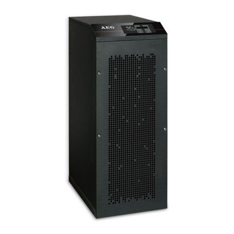
AEG Fluxpower HE Series Installation and operation manual

INSTALLATION AND START-UP MANUAL
EN
Fluxpower HE 10 kVA
Fluxpower HE 15 kVA
Fluxpower HE 20 kVA
Fluxpower HE 30 kVA
Fluxpower HE 40 kVA
Fluxpower HE

2

3
WARNING
This is a Class A-UPS Product. In a domestic environment, this product
may cause radio interference, in which case, the user may be take
additional measures.

4
1. Scope ..................................................................................7
2. Safety rules and warnings ................................................8
2.1 UPS use................................................................................ 8
2.2 Fluxpower HE rating ............................................................. 9
2.3 Special safety warnings ...................................................... 10
2.3.1 General warnings........................................................ 10
2.3.2 Personnel.................................................................... 10
2.3.3 Transport and handling ............................................... 10
2.3.4 Installation................................................................... 11
2.3.5 Electrical connection ................................................... 12
2.3.6 Operation .................................................................... 13
2.3.7 Maintenance ............................................................... 14
2.3.8 Storage ....................................................................... 15
2.4 Environmental protection .................................................... 15
2.4.1 ISO 14001 certification................................................ 15
2.4.2 Recycling of packing materials.................................... 15
2.4.3 Device disposal........................................................... 15
3. Installation ........................................................................16
3.1 Receipt of the UPS ............................................................. 16
3.1.1 Storage ....................................................................... 16
3.2 Handling of the UPS ........................................................... 16
3.3 Positioning and installation ................................................. 17
3.3.1 Base plan, static load and weights.............................. 18
3.3.2 Overall dimensions, minimum distances from
the walls and ventilation .............................................. 19
3.3.3 Environmental installation conditions .......................... 21
CONTENT

5
4. Electrical connection.......................................................25
4.1 Terminal boards.................................................................. 27
4.2 Connection of power cables................................................ 28
4.3 Battery ................................................................................ 28
4.3.1 Battery connection and positioning ............................. 29
4.3.1.1 3.3 Ah 12 V battery connection and
positioning Fluxpower HE 10 kVA ....................... 30
4.3.1.2 7 Ah / 9 Ah 12 V battery connection and
positioning – Fluxpower HE 10-15-20 kVA .......... 33
4.4 Fuses positioning BCB – Fluxpower HE 10-15-20 kVA ..... 36
4.5 AS553 external battery ....................................................... 37
4.5.1 Dimensions and weights ............................................. 38
4.5.2 7 Ah/9 Ah/12 Ah 12 V battery connection and
positioning 120 elements. ........................................... 40
4.5.3 Connections ................................................................ 42
4.6 Serial interfaces .................................................................. 42
4.7 Relay card connection (optional)......................................... 44
4.8 Back-feed protection (optional only for 30 – 40 kVA) .......... 46
5. Start-up and shutdown....................................................47
5.1 Preliminary checks.............................................................. 47
5.2 Start-up procedure .............................................................. 47
5.3 Basic troubleshooting.......................................................... 49
5.4 Shut-down procedure.......................................................... 50
5.5 Switching procedure to manual bypass .............................. 50
5.6 Restart from manual bypass ............................................... 52

6
Figure 1: Rating plate of Fluxpower HE........................................................... 9
Figure 2: Handling of Fluxpower HE.............................................................. 17
Figure 3: Base plan....................................................................................... 18
Figure 4: Minimum distances fromthe walls.................................................. 19
Figure 5:Terminal board Fluxpower HE Three phase 10-15-20 kVA.............. 27
Figure 6: Terminal board Fluxpower HE Three phase 30 – 40 kVA ............... 27
Figure 7: Cabling of BCB fuse holder ............................................................ 29
Figure 8: Cardboard 3.3 Ah battery protection............................................... 30
Figure 9: 3.3 Ah batteryconnection............................................................... 31
Figure 10: 3.3 Ah batteryconnected.............................................................. 32
Figure 11: Cardboard 7Ah/9Ah battery protection ......................................... 33
Figure 12: 7Ah/9 Ah batteryconnection ....................................................... 34
Figure 13: 7Ah/9 Ah batteryconnected ........................................................ 35
Figure 14: Fuses positioning on the fuse holder BCB .................................... 36
Figure 15: Base planofthe external battery cabinet....................................... 38
Figure 16: Dimensions of the external battery cabinet ................................... 38
Figure 17: Cardboard 7 Ah/9 Ah/12 Ah battery protection ............................. 40
Figure 18: 7Ah/9 Ah/12 Ah battery connection ............................................. 40
Figure 19: 7Ah/9 Ah/12 Ah battery connection ............................................. 41
Figure 20: Batterycircuit breaker and fuses .................................................. 41
Figure 21: Batterycabinet and UPS connections .......................................... 42
Figure 22: Interfaces of Fluxpower HE .......................................................... 43
Figure 23: Relay card.................................................................................... 44
Figure 24: Fuse F12 back-feed protection 30 – 40 kVA................................. 46
INDEX OF FIGURES

7
The instructions contained in the operating manual are applicable to the whole
production range of Fluxpower HE three phase UPS systems, as indicated
below.
•Fluxpower HE 10 kVA
•Fluxpower HE 15 kVA
•Fluxpower HE 20 kVA
•Fluxpower HE 30 kVA
•Fluxpower HE 40 kVA
STORING DOCUMENTATION
This manual and any other supporting technical documentation relating to the
product must be stored and made accessible to personnel in the immediate
vicinity of the UPS.
FURTHER INFORMATION
In the event that the information provided in this manual is not sufficiently
exhaustive, please contact the manufacturer of the device, whose details
are available in the “Contacts”section.
1. SCOPE

8
2.1 UPS USE
Congratulations on choosing a product from AEG Power Solutionsfor the
safety of your equipment. To obtain the best performance from your
Fluxpower HE UPS system (Uninterruptible Power Supply), we suggest
that you take your time to read the following manual.
The purpose of this manual is to give a short description of the parts
composing the UPS and to guide the installer or the user through the
installation of the unit in its using environment.
The installer or the user must read and correctly perform the instructions
included in the present manual, with particular reference tothe requirements
regarding safety, in compliance with the current regulations.
READ THE TECHNICAL DOCUMENTATION
Before installing and using the device, make sure you have read and
understood all the instructionscontained in the present manual and
in the technical supporting documentation.
2. SAFETY RULES AND WARNINGS

9
2.2 FLUXPOWER HE RATING
Fluxpower HE is provided with an identification plate containing the operation
ratings. The plate is fixed outside, on the rear of UPS.
CHECK THE TECHNICAL CHARACTERISTICS
Before carrying out any installation or start-up operation on the UPS, make
sure its technical characteristics are compatible with the AC supply line and
with the output loads.
Figure 1: Rating plate of Fluxpower HE

10
2.3 SPECIAL SAFETY WARNINGS
2.3.1 GENERAL WARNINGS
Fluxpower HE is provided with various stickers with indications regarding
specific dangers. These stickers must always be well visible and replaced
in cases where they are damaged. The present documentation must always
be available in proximity tothe device. Incase of loss we recommendto
request a copy from the manufacturer, whose details are available in the
“Contacts” section.
2.3.2 PERSONNEL
Any operation on Fluxpower HE must be carried out by qualified personnel.
By qualified and trained person we mean someone skilled in assembling,
installing, starting up and checking the correct operation of the product,
who is qualified to perform his/her job and has entirely read and understood
this manual, especially the part regarding safety. Such training and
qualification shall be considered as such, only when certified by the
manufacturer.
2.3.3 TRANSPORT AND HANDLING
Avoid bending or deforming the components and altering the insulation
distances while transporting and handling the product.
UNDISTRIBUTED WEIGHT
The weight of the UPS is not uniformly distributed.Pay attention when lifting.
Please inspect the device before installing it. In case any damage is observed
from the conditions of the package and/or from the outside appearance of the
equipment, contact the shipping company or your dealer immediately. The
damage statement must be made within 6 days of receipt of the product and
must be notified tothe shipping carrier directly. Should the product need to be
returned tothe manufacturer, please use the original package.
INJURY HAZARD DUE TO MECHANICAL DAMAGE
Mechanical damagetothe electrical components constitutes a serious danger
to persons and property. Incase of doubt regarding the non-integrity of the
package or of the product contained therein, contact the manufacturer before
carrying out the installation and/or the start-up.
11
2.3.4 INSTALLATION
The product must be installed in strict compliance with the instructions
contained in the technical back-up documentation, including the present safety
instructions. In particular, the following points must be taken into account:
•The product must be placed on a base suitable for carrying its weight and
that ensures a vertical position;
•The UPS must be installed in a room with restricted access, according to
standard IEC EN62040-1-2;
•Never install the equipment near liquids or in an excessively damp
environment;
•Never let a liquid or foreign body penetrate inside the device;
•Never block the ventilation grates;
•Never expose the device to direct sunlight or place it near a source of heat.
SPECIAL ENVIRONMENTAL CONDITIONS
Fluxpower HE is designed for normal climatic and environmental operating
conditions as defined in the technical specification: altitude, ambient operating
temperature, relative humidity and environmental transport and storage
conditions. It is necessary to implement specific protective measures in case of
unusual conditions:
•harmful smoke, dust, abrasive dust;
•humidity, vapor, salt air, bad weather or dripping;
•explosive dust and gas mixture;
•extreme temperature variations;
•bad ventilation;
•conductive or radiant heat from other sources;
•strong electromagnetic fields;
•radioactive levels higher than those of the natural environment;
•fungus, insects, vermin.
USE AUTHORIZED PERSONNEL ONLY
All transport, installation and start-up operations must be carried out by
qualified and trained personnel.
The installation of Fluxpower HE must be carried out by authorized personnel,
in compliance with national and local regulations.

12
DO NOT MODIFY THE DEVICE
Do not modify the device in any way: this may result in damage to the
equipment itself as well as to objects and persons. Maintenance and repair
must be carried out by authorized personnel only. Contact the manufacturer
for details of the nearest service center.
2.3.5 ELECTRICAL CONNECTION
The UPS connection tothe AC power must be carried out in compliance with
the current regulations.
Make sure the indications specified on the identification plate correspond to
the AC power system and to the actual electrical consumption of all of the
equipment connected.
CHECK THE CONFORMITY OF THE DOCUMENTATION
The UPS must be installed according to the requirements of HD 384.4.42
S1/A2 and in compliance with standard IEC 60364-4-482 – Chapter 482:
protection against fire.
Before connecting the unit tothe distribution network, make sure you have
received the approval of the relevant electrical power distribution authority, as
provided for by the current national regulations.
All the electrical connections must be carried out by authorized personnel.
Before connecting the device make sure that:
•the connection cable tothe AC line is properly protected;
•the nominal voltages, the frequency and the phase rotation of the ACsupply
are respected;
•the polarities of the DC cables coming from the battery have been checked;
•no leakage current to earth is present.
The device is connected to the following voltage supplies:
•DC battery voltage;
•AC mains voltage;
•AC bypass voltage.

13
INJURY HAZARD DUE TO ELECTRIC SHOCK!
The device is subject to high voltages, thus all safety instructions must be
scrupulously adhered to before performing any operation on Fluxpower HE:
•Isolate the battery via DC circuit breakers before connecting it tothe UPS
•Connect the ground cable tothe relevant bar before carrying out any other
connection inside the device
INJURY HAZARD DUE TO ELECTRIC SHOCK!
If primary power isolators are installed in an area other than the UPS one,
you must stick the following warning label on the UPS. “ISOLATE THE
UNINTERRUPTIBLE POWER SUPPLY (UPS) BEFORE WORKING ON
THIS CIRCUIT”
2.3.6 OPERATION
The installation to which the UPS systems belong must comply with all the
current safety standards (technical equipment and accident-prevention
regulations). The device can be started, operated and disconnected only
by authorized personnel.
The settings can only be changed using the original interface software.
INJURY HAZARD DUE TO ELECTRIC SHOCK!
During operation, Fluxpower HE converts power characterized by high
voltages and currents.
•All the doors and the covers must remain closed.
INJURY HAZARD DUE TO CONTACT WITH TOXIC SUBSTANCES
The battery supplied with the UPS contains small amounts of toxic materials.
To avoid accidents, the directives listed below must be observed:
•Never operate the UPS if the ambient temperature and relative humidity
are higher than the levels specified in the technical documentation.
•Never burn the battery (risk of explosion).
•Do not attempt to open the battery (the electrolyte is dangerous for the eyes
and skin).
Comply with all applicable regulations for the disposal of the battery.

14
2.3.7 MAINTENANCE
Service and repairs must be carried out by skilled and authorized personnel.
Before carrying out any maintenance operation, Fluxpower HE must be
disconnected from AC and DC supply sources.
The device is provided with internal isolators which allow it to isolate the
internal power circuits. However the voltages of the supply sources are present
at the terminals. To isolate the device completely, provide externalcircuit
breakers on the lines.
The device contains dangerous voltages even after shutdown and
disconnection from the supply sources, due to the internalcapacitors which
discharge slowly. Thus we recommendto wait at least 5 minutes before
opening the device doors.
INJURY HAZARD DUE TO ELECTRIC SHOCK!
Any operation must be carried out only when voltage is absent and in
compliance with safety directives.
•Make sure the battery circuit breaker that may be placed near the battery
has been opened
•Isolate the device completely by operating the externalcircuit breakers
•Wait at least 5 minutes in order to allow the capacitorsto discharge
After switching off and disconnecting the device there might still be very hot
components (magnetic parts, heatsinks); therefore we recommend using
protective gloves.
HIGH TEMPERATURE OF COMPONENTS
It is strongly recommended to use protective gloves due to the high
temperaturesthat may be reached during operation.

15
2.3.8 STORAGE
If the product is stored prior to installation, it should remain stored in its original
package in a dry place with a temperature ranging from -10 °C to +45 °C.
SPECIAL ENVIRONMENTAL CONDITIONS
It is necessaryto implement specific protective measures in case of unusual
environmental conditions:
•harmful smoke, dust, abrasive dust;
•humidity, vapor, salt air, bad weather or dripping;
•explosive dust and gas mixture;
•extreme temperature variations;
•bad ventilation;
•conductive or radiant heat from other sources;
•fungus, insects, vermin.
2.4 ENVIRONMENTAL PROTECTION
2.4.1 ISO 14001 CERTIFICATION
AEGPOWER SOLUTIONS is particularly sensitive to the environmental
impact of its products. That is why Fluxpower HE has been manufactured with
cutting-edge eco-design criteria (ISO 14001 certification).
Special care was taken in using fully recyclable materials and in reducing the
amounts of raw materials used.
2.4.2 RECYCLING OF PACKING MATERIALS
Packing materials must be recycled or disposed of in compliance with
applicable local and national laws and regulations.
2.4.3 DEVICE DISPOSAL
At the end of their product life, the materials composing the device must be
recycled or disposed of in compliance with the current local and national laws
and regulations.

16
3.1 RECEIPT OF THE UPS
Please inspect the device before installing it. In case any damage is noticed
from the conditions of the package and/or from the outside appearance of
the equipment, contact the shipping company or your dealer immediately.
The damage statement must be made within 6 days of receipt of the product
and must be notified to the shipping carrier directly. Should the product need
to be returned to the manufacturer, please use the original packaging.
DANGER TO PERSONS DUE TO TRANSPORTATION DAMAGE
Mechanical damagetothe electrical components constitutes a serious danger
to persons and property. Incase of doubt regarding the non-integrity of the
packaging or of the product contained therein, contact the manufacturer before
carrying out the installation and/or the start-up.
3.1.1 STORAGE
The package normally ensures protection from humidity and possible
damages during transport. Do not store the UPS outdoors.
RISK OF DAMAGE DUE TO INAPPROPRIATE STORAGE
•For the environmental storage conditions, refer to the indications given for
the installation of the device.
•The device must only be stored in rooms protected from dust and humidity.
•The device cannot be stored outdoors.
3.2 HANDLING OF THE UPS
The UPS is packed on a pallet. It is handled from the transport vehicle to the
installation (or storage) place via a fork lift.
THE DEVICE IS HEAVY
•Avoid turnover during the transport of the UPS.
•Cabinets must always be handled in upright position.
•During loading and unloading operations, always respect the indications
regarding the device “right way up” orientation marked on the packaging.
Before positioning the UPS, and in order to avoid risk of turnover,
it’s recommended to move the system on the wood pallet on which the
UPS is fixed.
Before positioning in its final location, remove the UPS from the pallet.
3. INSTALLATION

17
HANDLING OF THE UPS
The Fluxpower HE can be handled by means of the four wheels fixed
onto the bottom.
4x Wheels
3.3 POSITIONING AND INSTALLATION
Fluxpower HE must be installed indoors, in a clean and dry room, preferably
without dust or humidity incursion. For the environmental conditions in the
place of installation, in compliance with the current legislation, please refer
to the “Overall dimensions, minimum distances from the walls and ventilation”
section.
SPECIAL ENVIRONMENTAL CONDITIONS
It is necessaryto implement specific protective measures in case of
unusual environmental conditions:
•harmful smoke, dust, abrasive dust;
•humidity, vapor, salt air, bad weather or dripping;
•explosive dust and gas mixture;
•extreme temperature variations;
•bad ventilation;
•conductive or radiant heat from other sources;
•fungus, insects, vermin.
Figure 2: Handling of Fluxpower HE

18
3.3.1 BASE PLAN, STATIC LOAD AND WEIGHTS
Power (kVA) 10 15 20 30 40
Three phase
L1 (mm) 450
P1 (mm) 640
L2 (mm) –
The supporting base of the UPS must be designed tocarrythe UPS weight
and to ensure its steady and safe support.
Its carrying capacity must be adequate for the static loads indicated in the
table below.
Power (kVA) 10 15 20 30 40
Three phase
Weight without battery (kg) 100 110 140
Weight with battery (max) (kg) 285 275 –
Static load without battery (kg/m2) 347 381 486
Static load with battery (max) (kg/m2) 989 954 –
Figure 3: Base plan

19
3.3.2 OVERALL DIMENSIONS, MINIMUM DISTANCES
FROM THE WALLS AND VENTILATION
The UPS must be so installed as to ensure its serviceability and to allow a
correct air flow as much as possible.
With regard tothe minimum distances from the walls, for all of the UPS sizes
the same installation conditions apply as indicated in the table below.
Figure 4: Minimum distances from the walls

20
Power (kVA) 10 15 20 30 40
Three phase
L - mm 450
P - mm 640
H - mm 1200
X (min.)
- mm 50 100
Y (min.) - mm 500
ADD. CABINET
COD. AS553
L1 - mm 503
P1 - mm 647
H1 - mm 1200
The table below shows the air volume required for optimal ventilation and
cooling of the UPS.
Power (kVA) 10 15 20 30 40
Three phase
Air volume (m
3/h) 500 600 800 900
This manual suits for next models
5
Table of contents
Other AEG UPS manuals

AEG
AEG CompuMaster 300 User manual

AEG
AEG Protect C LCD 6000 (S) User manual

AEG
AEG Protect D Series User manual

AEG
AEG Protect C 1000 LCD+ User manual

AEG
AEG UPS 10 kVA User manual

AEG
AEG PROTECT A. 500 User manual

AEG
AEG Protect D Series User manual

AEG
AEG Protect C.1000 User manual

AEG
AEG Protect Home. 600 User manual

AEG
AEG Protect 5.31 User manual

AEG
AEG Protect 2.33 2.0 User manual

AEG
AEG Protect Home User manual

AEG
AEG PROTECT C. 10000 User manual

AEG
AEG Protect A Series User manual

AEG
AEG Protect NAS Owner's manual

AEG
AEG IST7 User manual

AEG
AEG PROTECT 1 Series User manual

AEG
AEG Protect 1. M User manual

AEG
AEG Protect C.3000 User manual

AEG
AEG PDU 10-1 User manual