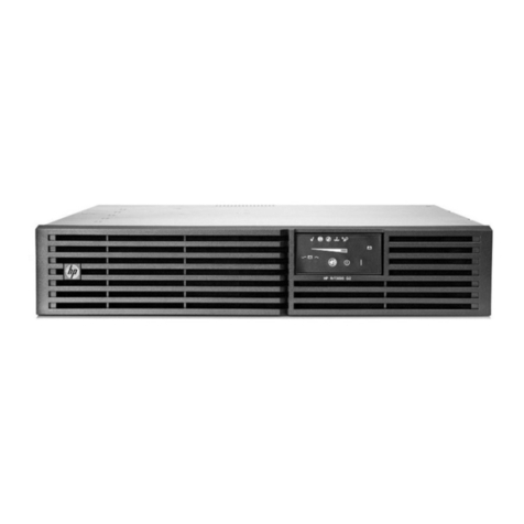
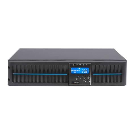
Chloride LP061XHR Operator's manual


Chloride Linear Plus Rack-Mount UPS User Instruction Manual
IMPORTANT SAFETY INSTRUCTIONS
SAVE THESE INSTRUCTIONS.
This manual contains important instructions for models:
Follow these instructions during the unpacking, installation, and maintenance of the UPS. If you have a
problem with the UPS, please refer to this manual before calling technical services.
Entirecontentscopyright©2007ChlorideGroupPLC.Allrightsreserved.Reproductioninwholeorinpartwithoutpermissionisprohibited.Allinformation
subject to change without notice.
913-610 @ Rev. B 07/07
• LP061XHR • LP101XHR • LPBP100-2
Chloride
27944 North Bradley Road
Libertyville, IL 60048-9700
USA
Chloride
George Curl Way
Southampton, Hampshire
SO18 2RY
United Kingdom
T (847) 816-6000
(800) 327-8801
F (847) 680-5124
www.chloride-na.com
T +44 (0) 2380 610311
F +44 (0) 2380 649994


i
Introduction .........................................................................................................................................................................................1
Registering Your UPS .........................................................................................................................................................................1
Technical Support ...............................................................................................................................................................................1
FCC Compliance .................................................................................................................................................................................1
Safety Compliance ..............................................................................................................................................................................1
Safety ...................................................................................................................................................................................................1
Intended Use ................................................................................................................................................................................1
Safety Notices ..............................................................................................................................................................................2
Emergency ...................................................................................................................................................................................3
Leakage Currents .........................................................................................................................................................................3
Radio Interference ........................................................................................................................................................................3
Batteries .......................................................................................................................................................................................3
Repackaging .................................................................................................................................................................................3
Notes Regarding the EU Declaration of Conformity ...................................................................................................................3
About the Operating Instructions ........................................................................................................................................................4
Device Overview ..........................................................................................................................................................................4
Symbols ........................................................................................................................................................................................4
Documentation Structure .............................................................................................................................................................4
Preparation for Use ..............................................................................................................................................................................4
Delivery and Storage ....................................................................................................................................................................4
Installation ...........................................................................................................................................................................................7
Electrical Preparations .................................................................................................................................................................7
Installation Data ...........................................................................................................................................................................8
Cable Sizes and Current ...............................................................................................................................................................9
Neutral Connection ....................................................................................................................................................................10
External Protection and Isolating Devices .................................................................................................................................10
Installation of Differential Protection Devices ..........................................................................................................................10
Terminal Blocks for UPS ...........................................................................................................................................................11
Connecting Mains ......................................................................................................................................................................12
Connecting Load Cables ............................................................................................................................................................12
External Battery Connection ......................................................................................................................................................12
Auxiliary Backfeed Protection ...................................................................................................................................................13
Operation ....................................................................................................................................................................................13
Reset ...........................................................................................................................................................................................13
Operating the Device .........................................................................................................................................................................13
UPS Start-Up Procedure ............................................................................................................................................................14
UPS Shutdown Procedure ..........................................................................................................................................................15
Functional Test ...........................................................................................................................................................................15
Indication and Operating Elements Linear Plus Rack-mount ....................................................................................................15
Indication and Operating Elements ............................................................................................................................................16
Remote Power Off (RPO) ..........................................................................................................................................................18
Emergency Power Off (ESD hardwired) ...................................................................................................................................19
Paralleling UPS Devices ............................................................................................................................................................19
Designing a Parallel System ......................................................................................................................................................19
Parallel System, Installation and Operating ...............................................................................................................................19
Maintenance ......................................................................................................................................................................................21
Battery Replacement ..................................................................................................................................................................21
Storage .......................................................................................................................................................................................22
Cleaning .....................................................................................................................................................................................22
Interfaces ...........................................................................................................................................................................................22
Serial Interface COM 3 ..............................................................................................................................................................22
Optional Isolated Contacts Card ................................................................................................................................................24
Troubleshooting ................................................................................................................................................................................25


Introduction
1 Chloride Linear Plus Series Rack-mount UPS User Instruction Manual
Introduction Thank you for selecting this uninterruptible power supply (UPS). Chloride’s Linear Plus Rack-mount
Series UPS offers the most reliable protection from the harmful effects of electrical line disturbances for
your computing and communications equipment. Chloride’s ISO 9001 certification represents our
commitment to building world-class products. We take pride in every unit that leaves our facility.
Registering
Your UPS To ensure that your Linear Plus Rack-mount Series UPS model and serial number are registered, complete
and mail the enclosed postage-paid warranty card.
Technical
Support Chloride offers 24-hour technical support. To contact Chloride Service:
• North America: (847) 816-6000, option 3
or toll free (800) 327-8801, option 3.
Please check with Chloride Service for assistance ordering, replacing, or disposing of batteries. Please
check with Chloride Service before attempting to repair or return any Chloride product. If a Chloride UPS
needs repair or replacement, Service will issue a Return Material Authorization (RMA) number along
with instructions on how to return the UPS.
FCC
Compliance ATTENTION: Changes or modifications to this unit not expressly approved by the party responsible or
in FCC compliance could void the user’s authority to operate the equipment.
This equipment was tested and complies with the limits for a Class A digital device, pursuant to Part 15
of FCC Rules. These limits are designed to provide reasonable protection against harmful interference
when the UPS is operating in a commercial environment. The UPS generates, uses, and can radiate radio
frequency energy. If installation and use is not in accordance with the instruction manual, it may cause
harmful interference to radio communications.
ATTENTION: Operation of this equipment in a residential area may cause harmful radio
communications interference. The user is responsible for correcting the interference.
Safety
Compliance UL listing to UL1778
TUV compliance to EN62040-1
CE
Safety This device serves as an uninterruptible power supply for connected loads. The device is in compliance
with all relevant safety regulations concerning information technology equipment, including electronic
machines for use in an office environment.
Depending on the type and rating of UPS device, certain configurations of battery extensions must be
connected. These battery extensions may only be connected to the compatible basic UPS unit.
This system, henceforward the “unit”, serves as uninterruptible power supply for connected loads,
available for use in 19-inch racks. The 6 kVA and 10 kVA must be operated with at least one rack-mount
battery extension. These battery extensions may only be connected electrically with the corresponding
base UPS unit.
WARNING: Chloride considers the safety of personnel to be of paramount importance. For this reason
it is essential that procedures relating to safety be studied before commencing work, and properly adhered
to thereafter.
Intended Use

Safety
Chloride Linear Plus Series Rack-mount UPS User Instruction Manual 2
•TheUser or Operator may intervene in the operation of the UPS provided that the instructions laid
out in “Batteries” on page 3, “Control Panel for the Linear Plus Rack-mount” on page 16 and
“Indication and Operating Elements Linear Plus Rack-mount” on page 15 are strictly adhered to.
• The “Installation” of the UPS, described in “Installation” on page 7, may only be carried out by
qualified technical personnel.
• Even when all switches and interrupters are open, hazardous voltages are present within the UPS; any
operation that requires protection panels to be opened and/or removed must be carried out by Chloride
authorized technical personnel only.
The Linear Plus Rack-mount Series UPS listed in Table 1 on page 4, with a mounting height of 3 U (1 U
= 1.75” (44.45 mm)], are designed for horizontal installation in 19-inch racks of industrial standard.
Safety Notices WARNING: Carefully read the following safety notices! Failure to observe the instructions may
endanger your life, your health, the reliability of your device or the security of your data.
• Transport the unit only in suitable packaging (protected against jolts and shocks).
• If the equipment is moved from a cold environment to the operating room, condensation may occur.
Before you switch on the equipment it must be absolutely dry. An acclimatization period of at least
two hours is required.
• The equipment must be installed in accordance with the environmental conditions specified
in “Environmental conditions” on page 5 and in Table 3 on page 8.
• Even with all buttons in “OFF” (see chapter “Control Panel for the Linear Plus Rack-mount” on page
16) the device (UPS) is not isolated from the mains. To isolate completely from the mains, the power
cables must be disconnected.
• In case of interruption of the mains voltage, the integrated battery maintains the power supply to the
user equipment.
• Lay all cables so that nobody can stand on them or trip over them. When connecting the device to the
power supply, follow the instructions in the chapter “Installation” on page 7.
• Make sure that no objects (e.g. pins, necklaces, paper clips, etc.) inside the device.
• In emergencies (e.g. damaged case, controls or power cables, penetration of liquids or foreign matter)
switch off the device and contact the appropriate customer service representative.
• Do not connect equipment that will overload the UPS (e.g. laser printers or vacuum cleaners) or
demand DC-current (e.g. half-wave rectifiers).
• When cleaning the unit, follow the instructions in the chapter “Maintenance” on page 21.
• The sum of the leakage currents (protective conductor current) of the UPS and the connected devices
exceeds 3.5 mA for all ratings of the UPS. Earth connection is essential before connecting supply.
• Data transmission lines should not be connected or disconnected during a thunderstorm.
• Emergency Power Off (EPO) input is located on the rear of the unit (see Fig. 5 on page 11). When this
connection is open, the logic circuit will immediately shut down the UPS output.
• In order that the wiring installation safety comply to the European Harmonized Document
HD384-4-46 S1, an Emergency Switching Device (E.S.D.) shall be fitted downstream of the UPS.
• When mounting the unit into a rack, it has to be hooked on both sides and the front plate of the unit
has to be fixed to the rack by screws. The unit has to be fixed in horizontal position.
• Do not connect:
- more than 5external batteries to the Linear Plus Rack-mount 6 KVA.
- more than 5 external batteries to the Linear Plus Rack-mount 10 KVA.
• The vents for air intake and outlet at the front and rear side must not be obstructed.
• Linear Plus Rack-mount UPSs are equipped with additional safety relays, that protect the input
terminals in special cases.

Safety
3 Chloride Linear Plus Series Rack-mount UPS User Instruction Manual
Emergency WARNING: The supply to the load may be interrupted by opening all the switches.
WARNING: DO NOT USE WATER to extinguish any fires that may occur in the area in which the UPS
is installed.
Leakage Currents WARNING: Connect the earth ground [protection earth (PE)] safety conductor before any other cables
are connected.
Radio Interference Linear Plus Rack-mount is a class A product.
The UPS device may cause radio interference. Do not place it near devices which are especially
susceptible to electromagnetical interference (e.g. transmitters/receivers, radar, metal detectors, anti-theft
devices).
Batteries Battery maintenance must be carried out by authorized personnel.
• The batteries installed in external battery cabinets may contain electrolyte. Under normal conditions
the containers are dry. A damaged battery may leak electrolyte which can be dangerous in contact with
the skin and cause irritation to the eyes. Should this happen wash the affected part with copious
amounts of water and seek immediate medical advice.
• Voltage is always present on the battery contacts.
• Even when discharged a battery has the capacity to supply a high short circuit current, which, in
addition to causing damage to the battery itself and to associated cables, may expose the operator to
the risk of burns.
• The voltage of a single cell of a single battery block is not dangerous. However a number of cells or
battery blocks, connected in series, can produce hazardous voltages.
• The battery is a “hermetic” type battery and must not be kept in storage or disuse for periods
exceeding 6 months at 68°F (20°C) without being recharged (having been charged to 100% at the
beginning of any such period). If this period is exceeded it is essential that the batteries be recharged,
which requires that the UPS be switched on. If these conditions are not respected the performance of
the battery can no longer be guaranteed. We advise recharging the batteries at least once every 4
months.
• Since new batteries often do not provide full capacity after an initial charge it may be necessary to
carry out a number of discharge/recharge cycles before optimum performance is achieved.
• In order to protect the environment batteries must be disposed of in accordance with the regulations
governing disposal of toxic and harmful waste.
Repackaging To re-pack, proceed as follows:
1. Do not pack the equipment until at least six hours have elapsed since the last recharge.
2. Place the equipment in bags made of a material sufficiently porous to allow it to breathe (e.g. 100μm
polyethylene).
3. Do not remove air from the packaging.
Notes Regarding the
EU Declaration of
Conformity
The Linear Plus Rack-mount devices conform to the following European directives:
73/23/EEC
Directive of the council for adaptation of the legal regulations of the memberstates regarding electrical
equipment for use within specific voltage limits, modified by directive 93/68/EEC.
89/336/EEC
Directive of the council for adaptation of the legal regulations of the member states regarding
electromagnetic compatibility, modified by directive 91/263/EEC, 92/31/EEC and 93/68/EEC.

About the Operating Instructions
Chloride Linear Plus Series Rack-mount UPS User Instruction Manual 4
Conformity is established through compliance with the following standards:
• EN 62040-1-1
• EN 62040-2
Additional information regarding adherence to these directives is included in the appendices NSR and
EMC of the EU Declaration of Conformity.
If required, the EU Declaration of Conformity can be requested from Chloride.
About the
Operating
Instructions
This manual contains information regarding the installation, operation and use of the Uninterruptible
Power Supply (UPS) Linear Plus Rack-mount.
It is advised that this User’s Manual be consulted before installation of the equipment, which operation
shall only be carried out be qualified personnel. Thereafter, it shall be kept and referred to whenever it is
necessary to carry out work on the UPS.
Device Overview The Linear Plus Rack-mount devices are available at various nominal power ratings.
The following table provides an overview of the various versions of the device:
Symbols The following symbols are used in this handbook:
WARNING: indicates instructions which, if not observed, may endanger your life, your health, the
reliability of your device or the security of your data.
NOTE: Indicates additional information and tips.
Documentation
Structure These instructions can be supplemented with additional sheets, describing, for example, specific
extensions, options or device status.
Preparation for
Use Delivery
The goods have been checked thoroughly before dispatch. On receipt check the packaging and ensure that
the contents are undamaged. Any damage or missing parts must be reported to the supplier within 8 days
of delivery.
Introduction
Table 1. Overview of UPS devices and batteries (BP = Battery Pack)
Type Designation Order No. Nominal Power
19“ rack-mount UPS Linear Plus Rack-mount 6 kVA LP061XHR- 6000 VA
Linear Plus Rack-mount 10 kVA LP101XHR- 10000 VA
External Battery Standard External Battery LPBP100-2 NA
Delivery and Storage

Preparation for Use
5 Chloride Linear Plus Series Rack-mount UPS User Instruction Manual
Unpacking
The utmost care shall be taken when removing the packaging in order to avoid damaging the equipment.
Check all packaging materials to ensure that no items are discarded. Remove the packaging following the
sequence illustrated in Fig. 1.
Fig. 1: Unpacking
Storage
If it is not intended that the UPS be used immediately upon delivery, attention shall be paid to the storage
conditions.
If the batteries or the equipment are to be stored, they must be kept in a clean, dry environment and away
from extremes of temperature.
Handling
The equipment must be kept upright at all times and handled with care, damage may be caused if dropped
or subjected to severe impact.
Environmental conditions
The Linear Plus Rack-mount UPS must be installed horizontally, and in an area protected from extremes
of temperature, water and humidity and the presence of conductive powder or dust. (See Table 3 on page
8). Do not stack units and do not place any objects on top of a unit.
The functional temperature range of the UPS is 32°F to 104°F (0°C to 40°C).
The ideal ambient temperature range is 59°F to 77°F (15°C to 25°C). The maximum ambient operating
temperature is 104°F (40°C).
The battery life is defined at 68°F (20°C).Operation of the equipment above 77°F (25°C) reduces the
service life of the batteries dramatically.
Access to area
The area must have sufficient space for the installation operation to be carried out. Access doors must be
sufficiently large to permit passage of the unit (See “Installation” on page 7).
Rack loading
Taking into consideration the weight of the Linear Plus Rack-mount UPS/batteries as reported in Table 5
on page 9, it is necessary that the chosen cabinet be capable of supporting the weight of the unit / batteries.
Table 2. Storage data
Temperature limits - Batteries ONLY +32°F to +104°F (0°C to +40°C)
Temperature limits - UPS without batteries -13°F to +131°F (-25°C to +55°C)
Relative humidity from 10% to 90%
TOOLS KIT
PALLET JACK
SCISSORS
SCREWDRIVER

Preparation for Use
Chloride Linear Plus Series Rack-mount UPS User Instruction Manual 6
Inventory list
• Parallelable UPS types are equipped with
(1) control cable, 25-pin
(1) jumper for terminals S1-S2
• Linear Plus Rack-mount UPS contains (1) jumper for disabling the EPO circuit when not in use.
• Battery cabinets/racks contain (1) DC-power cable
• Linear Plus Rack-mount devices are equipped with (1) set of rails and rail guides (Fig. 2 on page 6)
• UPS devices only contain (1) user manual
Mechanical fixing of 19 inch units
Selection of the mounting location
NOTE: The Linear Plus Rack-Mount UPS and its battery racks are designed to be mounted horizontal
in 19-inch racks. When installing the units please consider the weight, especially of the battery extension.
Preferably the units should be installed in the lower section of the rack. UPS systems consisting of several
units must be installed so that the battery extensions are mounted in the lower section of the rack with the
UPS directly above.
Included in each Linear Plus Rack-Mount carton is a rail kit, part number 301-170. The Rail Kit consists
of the following components:
• Rail, left front, part number 203-710
• Rail, right front, part number 203-711
• Rail, rear, part number 203-645 (2 each)
• Bag, hardware part number 360-020
• Bag, hardware, part number 360-021
Before beginning installation, be sure all parts are identified.
Fig. 2: Rack Kit Installation
1. Using Fig. 2, assemble the left rail and right rail guides. Leave enough slack to permit final
alignments in the rack.

Installation
7 Chloride Linear Plus Series Rack-mount UPS User Instruction Manual
2. Position the left and right rail guides in the four-post rack and tighten all fasteners.
CAUTION: The rail guide for the lowest battery cabinet should be installed first at the lowest position in
the rack. Once the first battery is installed, then subsequent battery rail guides should be installed above.
The final rail guide assembly, located above the last battery cabinet, should support the UPS cabinet at
the top.
3. Using Fig. 3, assemble the mounting rails to the body of the UPS or battery extension.
4. Slide the Linear Plus battery chassis,with its left and right hand channels attached, onto the rail guide
until the front of the chassis is in contact with the front of the rail guide.
5. Fasten the chassis to the rack as shown in usig the screws (D) and flat washers (E).
Repeat for each subsequent chassis.
When all of the chassis units are securely in the rack continue with the electrical installation. See
“Electrical Preparations” on page 7.
The units must be secured in the rack on both sides. When using the UPS attached mounting rails (see
Fig. 3 below), the single unit can easily be inserted into a 3 U mounting space. In order to secure the unit
in the horizontal position, the front-plate has to be secured to the 19-inch rack at the indicated points on
both sides of the unit. It is not permissible to secure the unit only at the front-plate. This may damage the
unit and/or other mounted units.
Fig. 3: Mounting the rails to the body of the UPS or battery extension
Installation During installation the input source must be isolated and secured against the possibility of being
reconnected. The Input miniature circuit breaker located at the rear of the UPS and both circuit breaker
poles of the battery cabinet(s) must be in “OFF” position. Connect the UPS and battery cabinet(s)
according to these instruction.
NOTE: It must be ensured that the live input source cannot accidentally be connected to the UPS during
installation.
WARNING: Installation may be carried out only by qualified technicians and in conformity with the
applicable safety standards.
WARNING: Electrical shock hazard: Even when the unit is disconnected from the mains, hazardous
voltage may still be supplied by the battery. Both circuit breaker poles should, therefore, be disconnected
before carrying out maintenance or installation work inside the UPS.
For electrical installation, the nominal current rating of the source must be observed. The UPS must be
connected to a suitably rated circuit.
Mounting rail of UPS or bat-
tery extension on the right
side. A separate second rail is
mounted on the left side
Front plate
Electrical
Preparations

Installation
Chloride Linear Plus Series Rack-mount UPS User Instruction Manual 8
Installation Data
Table 3. Environment data
Ambient temperature +32°F to +104°F (0 °C to +40 °C)
Relative humidity (w/o condensing at 20°C) 90%
Max. altitude (w/o derating) 1000 m a.s.l.
Cable inlet bottom at the rear side
Air inlet front
Air outlet rear
Table 4. Electrical data Linear Plus Rack-mount 6 kVA/10 kVA
UPS-TYPE Linear Plus
Rack-mount 6 kVA Linear Plus
Rack-mount 10 kVA
Electrical Data
Rating 6 kVA 10 kVA
Input Voltage 208, 220, 230, 240 VAC, 1 phase
Frequency 50/60Hz ±5%,
automatic frequency sensing
Current @ 208 VAC 29 A 48 A
Battery
external
TypeaExternal battery
packs only (1 to 5
packs)
External battery
packs only (1 to 5
packs)
Voltage/Ah
Type 240V/ 20x (12V/8 Ah)
Yuasa Rew 45-12FR
Output
Voltage 208, 220, 230, 240V ±2%
Frequency with mains
control see input frequency
Frequency with internal
clock 50/60Hz ±0.5%
Nominal current at
cos ϕ= 0.7 and 208 V 28.8 A 48 A
General
Over voltage category II
Protection class IP 20
Cooling Ventilator
a. use battery type for replacement purpose also. No other type permitted

Installation
9 Chloride Linear Plus Series Rack-mount UPS User Instruction Manual
inearP
Cable Sizes and
Current The following table indicates the recommended sizes of conductors in accordance with the NEC®. (Air
temperature surrounding the conduits not greater than 86°F (30°C).)
NOTE: Cable sizes are suggested and based on standard configurations. Installers should verify correct
conductor sizes pursuant to NEC®and/or state or local codes. If the installation requires long conductor
runs, consult NEC®and/or state or local codes to account for electrical losses.
WARNING: Particularly sensitive equipment may be susceptible to interference, in order to prevent this
it is suggested that input, output and any external battery cables to the UPS be housed in earthed, metal
conduits or that shielded cables be used. Routing of cables (e.g. power supplies, communication or data
Table 5. Mechanical data Linear Plus Rack-mount 6 kVA/10 kVA
UPS-TYPE Linear Plus
Rack-mount 6 kVA Linear Plus
Rack-mount 10 kVA
Mechanical Data
UPS Net Weight - lbs (kg) 53 (24) 57 (26)
Unit dimensions Width 19 (482.6)
Height 5.1 (130)
Depth 26 (660) 28.1 (715)
Body dimensions
Dimensions - in (mm)
Width 16.1 (410)
Height 5.25 (130) (3 U)
Depth 26 (660)
Battery
extensions Type LPBP100-2
Weight - lbs (kg) 152 (69)
Battery
dimensions
Dimensions - in (mm)
Width (16.1) 410
Height 5.25 (130) (3 U)
Depth 26 (660) 26 (660)
Table 6. Cable Sizes
Term ID Description
6 kVA 10 kVA
main wire
gauge
(awg
term
torque
(in-lbs)
min wire
temp
(°C)*
main
wire
gauge
(awg
term
torque
(in-lbs)
min wire
temp (°C)*
MAIN
L/N Line 1 (Main) 840 75 645 75
LLine 2 (Main) 840 75 645 75
Chassis Ground ** 40 75 ** 45 75
OUTPUT
L/N Output Term 1 10 35 75 645 75
LOutput Term 2 10 35 75 645 75
Output Term 3 10 35 75 645 75
* Use insulated copper wire rated 75°C minimum.
** Must be no smaller than wire connected to mains L and L/N.
NOTE: For installation per IEC regulations: If installing units per regulations IEC-287 and DIN VDE 0298, 6 kVA model
should be wired (inputs and outputs) with 6 mm2cable torqued to 4.5 nt-m; and 10kVA model (inputs and outputs) should
be wired with 10 mm2cable torqued to 5.0 nt-m. (Based on 70°C cable and ambient of 30°C)

Installation
Chloride Linear Plus Series Rack-mount UPS User Instruction Manual 10
lines) to other equipment, should be kept separate from that of UPS cables.
Neutral Connection The installation of the UPS does not affect the existing Neutral system.
The Neutral system may be affected if the UPS is operating with the Neutral switched upstream.
External Protection
and Isolating
Devices
WARNING: A disconnect switch shall be provided by others for AC input/output circuit. To reduce the
risk of fire, connect only to a circuit provided with branch circuit over current protection for Table 7
Amperes rating in accordance with the National Electric Code, ANSI/NFPA 70.
The following table indicates the protection devices (circuit breakers and fuses) which must be installed
by the installing personnel for protection of both the cables and the equipment.
NOTE: The external battery cabinet shall be located adjacent to the UPS. When such an option is
supplied by Chloride it comes complete with protection devices and correctly-sized cables. When batteries
are sourced from other suppliers it is advised that Chloride be contacted for correct sizing of protection
devices and interconnection cables.
Installation of
Differential
Protection Devices
Fig. 4 illustrates the method of installing differential breakers.
To avoid spurious operation, differential protection devices must:
• be rated at differential current NOT LESS THAN 100 mA
• be a SELECTIVE type (delayed intervention)
• be Type A
Fig. 4: Standard configuration
Table 7. Fuses or circuit breakers
UPS Type Linear Plus Rack-mount
6kVA Linear Plus Rack-mount
10 kVA
Input Fuse / A 40 A 60 A
Circuit breaker / A 40 A 60 A
Output Circuit breaker 30 A 50 A
Output
External Battery Pack
D1

Installation
11 Chloride Linear Plus Series Rack-mount UPS User Instruction Manual
Terminal Blocks for
UPS The following figuresshow the units with the external battery extension.
To connect the external battery to the UPS, plug the battery cable (16) into the socket (9) and into a battery
extension socket (13).
Fig. 5: Rear View Linear Plus Rack-mount UPS (top), Battery (center), and Cable (bottom)
Legend:
NOTE: Each external battery cabinet is supplied with one battery connection cable (16). The first
16
14 12
15 13
16
|o
1. Output socket(s) IEC 320 - C19
2. 2 Output circuit breaker (for plugged outlets)
3. Input miniature circuit breaker
4. Fan
5. Cover of parallel port
6. Communication Slot (Option)
7. ESD Contacts (control)
7a. ESD Contacts, hardwired
8. UPS interface COM 3
9. Battery socket
10. Strain relief
11. Mains connection, Terminal Block
12. Battery socket for battery connection cable to
UPS
13. Battery extension cable socket. Connected to
UPS or another battery extension
14. Battery extension circuit breaker
15. Earth connection
16. Battery extension connection cable
17. S1, S2: Paralleling terminals (bridged 10
mm2if UPS works in single block mode,
open if UPS in parallel operation)
18. Terminals for backfeed control

Installation
Chloride Linear Plus Series Rack-mount UPS User Instruction Manual 12
extension is connected to the battery connection the UPS (9), each subsequent extension is connected by
means of the battery extension connection cables (16). The cables are designed to be
non-interchangeable, because the sockets (13) are coded.
Connecting Mains Connect the mains supply to the input terminals of the UPS (see Fig. 5 on page 11 and Table 6 on page 9).
Connecting parallel UPS configurations: refer to chapter “Paralleling UPS Devices” on page 19.
Connecting Load
Cables 1. Open UPS input breaker.
2. Remove terminal area safety cover.
3. Connect loads to “Output” terminals (see Fig. 5 on page 11 and Table 6 on page 9).
4. Connect mains to the corresponding input terminals (see Fig. 5 on page 11 and Table 6 on page 9).
Preparing single mode / parallel mode:
• If UPS is to be operated as single unit connect a 6 awg (10 mm2) jumper between S1 and S2.
• If UPS is to be operated as parallel unit ensure that no jumper is connected between S1 / S2.
External Battery
Connection WARNING:
•The batteries installed in external battery cabinet may contain electrolyte. Under normal conditions the
containers are dry. A damaged battery may leak electrolyte which can be dangerous in contact with the
skin and cause irritation to the eyes. Should this happen wash the affected part with copious amounts of
water and seek immediate medical advice.
•Do not open or damage batteries. The released electrolyte is toxic.
•Voltage is always present on the battery contacts.
•Even when discharged a battery has the capacity to supply a high short circuit current, which, in addition
to causing damage to the battery itself and to associated cables, may expose the operator to the risk of
burns. The following precautions should be observed when working on batteries:
• Remove watches, rings or other metal objects.
• Use tools with insulated handles.
•The voltage of a single cell of a single battery block is not dangerous. However a number of cells or
battery blocks, connected in series, can produce hazardous voltages.
•The accumulator is a “hermetic” type battery and must not be kept in storage or disuse for periods
exceeding 6 months at 68°F(20 °C) without being recharged (having been charged to 100% at the
beginning of any such period). If this period is exceeded it is essential that the batteries be recharged,
which requires that the UPS be switched on. If these conditions are not respected the performance of the
battery can no longer be guaranteed. We advise recharging the batteries at least once every 4 months.
•Since new batteries often do not provide full capacity after an initial charge it may be necessary to carry
out a number of discharge/recharge cycles before optimum performance is achieved.
•When replacing batteries, replace with the same type and number of batteries and battery packs.
•In order to protect the environment batteries must be disposed of in accordance with the regulations
governing disposal of toxic and harmful waste.
•Do not dispose of batteries in a fire. The batteries may explode.
Before Connecting the UPS and the external battery cabinet, check to see that the battery breaker is in the
“OFF” position.
The battery connection cable plug is keyed to the receptacles on the UPS and battery cabinet. Insure that
the plug notch is correctly aligned with the receptacle guide when connecting the components together.

Operating the Device
13 Chloride Linear Plus Series Rack-mount UPS User Instruction Manual
Auxiliary Backfeed
Protection To support protection against UPS backfeeding logic is integrated into Linear Plus Rack-mount.
Using backfeed protection
On customers side an additional magnetic contactor (MC) may be provided. The magnetic contactor must
be able to carry the UPS input current (see Table 4, “Electrical data Linear Plus Rack-mount 6 kVA/
10 kVA,” on page 8).
The MC has to be installed in the common input supply path. Cabling of the backfeed terminals contains
a jumper and two cables to the optional magnetic contactor.
Not using backfeed protection
For cabling the backfeed terminal board, please follow Fig. 6.
The factory setting of the backfeed terminal board, located on the UPS rear side, is shown there .
Fig. 6: Backfeed terminal board, factory setting
Operation If bypass thyristor is shorted (short circuit) and UPS runs in double conversion mode (online) the
following steps follow:
• the backfeed detection circuit activates, backfeed relay opens.
• Press the “o” button to acknowledge the fault.
Reset To reset the backfeed logic the UPS input circuit breaker/battery circuit breaker must be switched “OFF”
for 10 seconds
Operating the
Device Block diagram Linear Plus Rack-mount
Linear Plus Rack-mount 6 kVA and 10 kVA consists of the following main components
• mains supply
• input switch
• rectifier/booster, inverter and charger
• electronic bypass
• paralleling contactor
• RPO hardwired
• backfeed protection logic
• Battery racks are external.
P i n s
M a i n s 2 / L
M a i n s 2 / N
M C / c o i l , o u t
M C / c o i l , i n
M a i n s 2 / N , s e n s o r
Normal and Safe
Operating

Operating the Device
Chloride Linear Plus Series Rack-mount UPS User Instruction Manual 14
Fig. 7: Overview of components Linear Plus Rack-mount 6 kVA/10 kVA
Preliminary controls
Before switching on the UPS and supplying the load the following shall be observed:
• Ensure that the ventilation grilles are unobstructed.
• Ensure the ground (earth) connection is in place.
• Ensure that the load switches are in the OFF (0) position.
• Ensure that all UPS rear panel switches are in the OFF (0) position.
WARNING: As soon as the UPS is connected to the AC mains, the output sockets are live, even if the UPS
is not yet switched on via the front panel switch.
1. Switch ON the mains supply to the UPS Linear Plus Rack-mount.
When connected to the mains, the “LINE” and “BYPASS” LEDs on the control panel are illuminated
and the UPS starts recharging the connected (external) batteries immediately. Before using the
device, the batteries should be recharged for a period of 8 hours. The UPS may be used immediately,
even without charging, but will not be able to provide the specified autonomy.
2. Once recharging has been completed the UPS is ready for use, follow the UPS Start-Up Procedure -
see “UPS Start-Up Procedure” on page 14.
WARNING: Do not connect any devices that may overload the UPS or draw DC current.
NOTE: If these instructions are not observed correctly, problems may be experienced with the electrical
supply.
UPS Start-Up
Procedure 1. Ensure all the mains switches and circuit breakers upstream of the UPS are closed.
2. Ensure batteries are connected.
3. Switch the battery breaker to the closed ( | ) position.
4. Switch input breaker to “ON ’position ( | ).
5. The unit will go through a self-test. Wait for the yellow BYPASS LED to illuminate (approximately
15 seconds).
NN
L
6 k V A / 1 0 k V A R A C K
S
1
S
2
L
b l o c k L i n + E r a c k . d s f
Inverter
Charger
Battery fuse
Rectifier/
Booster
Mains
Automatic
bypass
Mains
External battery
UPS rack
Battery fuse
Battery rack
Battery rack
LL
ESD

Operating the Device
15 Chloride Linear Plus Series Rack-mount UPS User Instruction Manual
6. Close any external switches connecting the load (if present).
7. Press the button on the UPS control panel for a minimum of 1 second to switch on the inverter
(see “Control Panel for the Linear Plus Rack-mount” on page 16).
In addition to the “LINE” and “BYPASS” LEDs the “LOAD” LED and “BATTERY” LED is now
illuminated. After a few seconds the “INVERTER” LED is illuminated and the “BYPASS” LED is
extinguished. The UPS is now in ON-LINE operation.
UPS Shutdown
Procedure NOTE: Carrying out this procedure will interrupt the supply to the load.
1. Press the button on the UPS control panel for a minimum of 1 second to switch off the inverter.
2. Open any external switches connecting the load (if present).
3. Switch input breaker to position (0) OFF.
4. Switch off the battery breaker. to the open (O) position.
5. Ensure all mains switches and circuit breakers upstream of the UPS are open.
6. Ensure that all LEDs on the control panel are extinguished. The UPS is now completely shutdown.
Functional Test NOTE: Supply to the load is not guaranteed during this test, it should not be carried out if a critical load
is connected to the UPS.
It is possible to carry out a functional test of the UPS to ensure that the load is still supplied in the event
of a mains failure.
Simulate a mains failure by interrupting the mains supply to the UPS. If the UPS is operating correctly
and the batteries are fully charged, an acoustic signal at intervals of 4 seconds will be heard and the “ON”
LED indication “MAINS “indicator (6) at the UPS will be extinguished. Once the interval between the
acoustic signals has decreased to 1 second, the UPS will continue to supply energy for a maximum of 3
more minutes, after which it will be automatically switched off.
The load will be supplied from the batteries during the specified emergency supply period. If this is not
the case, please consult chapter “Troubleshooting” on page 25”.
Restore the UPS mains supply. The UPS is ready for operation. Please note, that the batteries have to be
recharged before the complete emergency supply period is again available.
NOTE: The unit indicates an alarm condition, when the battery is not connected.
Canceling the battery alarm
1. To cancel the alarm, connect the battery and close the battery breaker.
2. Switch the unit to online mode by pushing the button .
The unit checks the battery voltage (a beep is heard) once more and stays in bypass till a constant battery
voltage is present.
Battery maintenance must be carried out by authorized personnel observing the necessary precautions.
Parallel operation
Please refer to chapter “Paralleling UPS Devices” on page 19
Indication and
Operating Elements
Linear Plus
Rack-mount
NOTE: To effect any action, the buttons must be pressed for at least 1 second! (Acceptance of the input
is confirmed acoustically)
The following is an explanation of the symbols printed on the front panel of the UPS:
This manual suits for next models
2
Table of contents
Other Chloride UPS manuals
Chloride
Chloride Desk Power Plus 1000 User manual

Chloride
Chloride SE041XAT Operator's manual

Chloride
Chloride EDP70 Instruction Manual

Chloride
Chloride Power Protection Active 700 User manual
Chloride
Chloride Desk POWER 300 User manual

Chloride
Chloride Power Protection Active 700 User manual
Chloride
Chloride Cool Power 600 User manual
Chloride
Chloride CP3000 Series User manual

Chloride
Chloride EDP70 Instruction Manual

Chloride
Chloride Power Star User manual
