Sola 625 User manual

USER GUIDE
ups 625
700, 1000, 1500, 2000 & 3000VA
www.solaaust.com.au

u p s 625
700, 1000, 1500, 2000 & 3000VA
User Guide
Important Notice
The UPS ground (earth) conductor carries leakage current from the loads in addition to
any leakage current generated by the UPS. This UPS generates no more than 1 mA of
current. To limit the total leakage current to 3.5 mA, the load leakage must be limited to
2.5 mA. The three-wire receptacle that you plug the UPS into must have a good (low-
impedance) ground (protective earth) connection to provide a safe path for leakage cur-
rent.
OMM6253kRev0.qxd
© Copyright 2002, Invensys. All rights reserved.

If You Have a Question
Customer Support
If you have a question or problem, Table 10, Troubleshooting, may help. If you need
more help, please have your UPS model number and serial number (on the back
label) nearby, and call the Invensys office nearest you (see the Invensys offices
section). Invensys’ service technicians have in-depth knowledge of the UPS and power
problems.
Invensys may tell you the UPS must be returned. If this happens, we will give you a
Return Authorisation (RA) number. When you return a SOLA 625 to the factory for
any reason, please use the original packing material in which your unit was
shipped to you. You may be responsible for repair charges for damaged units
which are not packed in SOLA packing material. If you have discarded the original
packing material, please call the nearest Invensys office so that we can ship new pack-
ing material to you. If you have any questions, please feel free to call or fax the nearest
Invensys office. Please do not return your SOLA 625 without calling Invensys first.
Invensys will advise you where to ship your SOLA 625.
Invensys reserves the right to change specifications without prior notice.

1
SOLA Never Stops Innovating
Table of Contents
Safety Instructions . . . . . . . . . . . . . . . . . . . . . . . . . . . . . . . . . .2
1.0 UPS Features . . . . . . . . . . . . . . . . . . . . . . . . . . . . . . . . . . . . .3
2.0 Quick Startup . . . . . . . . . . . . . . . . . . . . . . . . . . . . . . . . . . . . . .6
3.0 Operation . . . . . . . . . . . . . . . . . . . . . . . . . . . . . . . . . . . . . . . . .7
3.1 UPS Front Panel . . . . . . . . . . . . . . . . . . . . . . . . . . . . . . . . . . .7
3.2 Turning the UPS On . . . . . . . . . . . . . . . . . . . . . . . . . . . . . .8
3.3 Turning the UPS Off . . . . . . . . . . . . . . . . . . . . . . . . . . . . . .8
3.4 Standby Mode . . . . . . . . . . . . . . . . . . . . . . . . . . . . . . . . . .8
3.5 Diagnostic Tests . . . . . . . . . . . . . . . . . . . . . . . . . . . . . . . . .8
4.0 Configuration . . . . . . . . . . . . . . . . . . . . . . . . . . . . . . . . . . . . . .9
5.0 Additional UPS Features . . . . . . . . . . . . . . . . . . . . . . . . . . . .12
5.1 Inverter Shutdown . . . . . . . . . . . . . . . . . . . . . . . . . . . . . .12
5.2 Network Transient Protector . . . . . . . . . . . . . . . . . . . . . . .12
5.3 Load Segments . . . . . . . . . . . . . . . . . . . . . . . . . . . . . . . .12
5.4 Communication Port . . . . . . . . . . . . . . . . . . . . . . . . . . . . .13
5.5 Comunication Slot . . . . . . . . . . . . . . . . . . . . . . . . . . . . . .13
5.6 SNMP/Web Adaptor . . . . . . . . . . . . . . . . . . . . . . . . . . . . .13
5.7 Relay Card . . . . . . . . . . . . . . . . . . . . . . . . . . . . . . . . . . . .14
6.0 Installing Lansafe Software . . . . . . . . . . . . . . . . . . . . . . . . . .14
7.0 Replacing the Batteries . . . . . . . . . . . . . . . . . . . . . . . . . . . . .15
7.1 How to Replace Internal Batteries . . . . . . . . . . . . . . . . . .16
7.2 Recyling the Used Battery . . . . . . . . . . . . . . . . . . . . . . . .16
8.0 Specifications . . . . . . . . . . . . . . . . . . . . . . . . . . . . . . . . . . . . .17
9.0 Troubleshooting . . . . . . . . . . . . . . . . . . . . . . . . . . . . . . . . . . .20
10.0 Warranty . . . . . . . . . . . . . . . . . . . . . . . . . . . . . . . . . . . . . . . .24
Invensys Australia/New Zealand Offices . . . . . . . . . . . . . . . . .28
Trademarks
Windows is a registered trademark of Microsoft Corporation.
All other brand and product names are trademarks or registered trademarks of their
respective holders.
SAVE TIME!
REGISTER NOW ON LINE at
www.solaaust.com.au/warranty_form.html

2
SOLA Never Stops Innovating
Safety Instructions
IMPORTANT SAFETY INSTRUCTIONS!
SAVE THESE INSTRUCTIONS!
This User Guide contains important instructions for your SOLA 625 that must be followed during
installation and maintenance of the UPS and batteries.
The installation and use of this product must comply with all national, federal, state, municipal, or
local codes that apply. For assistance, call Invensys Service or your local Invensys office.
If the SOLA unit has been damaged during shipment, call your vendor immediately.
If the SOLA unit is stored, the batteries should be recharged every 6 months. If stored
above 25°Celsius, recharge the batteries more often.
CAUTION!
Whenever the SOLA 625 is “On,” there may be dangerous voltage present at the unit’s outlets.
This is true because the unit’s battery supplies power even if the unit is not plugged into the
wall outlet. The unit contains dangerous voltages.
To reduce the risk of electric shock, install in a temperature-controlled and humidity-
controlled indoor area free of conductive contaminants.
The power supply cord is intended to serve as the disconnect device. The socket-outlet shall
be near the equipment and shall be easily accessible.
With the exception of the user-replaceable batteries, all servicing of this equipment must be
performed by qualified service personnel.
Before maintenance or repair, all connections must be removed. Before maintenance, repair,
or shipment, the unit must be completely switched off and unplugged or disconnected.

3
SOLA Never Stops Innovating
Fig 1. SOLA 625 Controls and Indicators
1.0 UPS Features
The SOLA 625 provides protection against power problems, including power outages, brownouts,
and sudden increases in power. It also provides spike suppression and line noise filtering to pro-
tect your equipment. Front panel LEDs and an audible alarm keep you aware of the unit’s status.
Use the drawings on this and the following pages to identify features of the unit.
LCD Panel
Power On
Indicator Alarm
Indicator
On Battery
Indicator
Scroll
Button On/Off
Button Enter
Button

4
SOLA Never Stops Innovating
ASSEM BLED IN TAIWAN
USE WITH:2BAT 700
612-09910-00
OUTPUT :208/220/230/240V,50/60H z
50/60H z,3.4/3.2/3.0/2.9A
INPUT :208/220/230V/240V,
MODELNO.:06250700A
INPUT :24V,25A
700VA /490W
P/N:06250700A
Fig 2. 700VA and 1000VA Rear Panel
Fig 3. 1500VA Rear Panel
USB Port Communication Slot
Communication Port
Fan
Inverter Shutdown
Connector
Load Segment 1
2 x Australian 10A
Input Connector
IEC C14 10A
Network Surge Suppression
Battery Connector
Load Segment 2
2 x Australian 10A
USB Port Communication Slot
Communication Port
Fan
Inverter Shutdown
Connector
P/O Load Segment 2
Australian 10A
Input Connector
IEC C14 10A
Network Surge
Suppression
Battery Connector
Load Segment 2
2 x Australian 10A
P/O Load Segment 1
Australian 10A

5
SOLA Never Stops Innovating
Fig 4. 2000VA Rear Panel
USB Port Communication Slot
Communication Port
Fan Inverter Shutdown
Connector
Input Connector
IEC C14 10A
Network Surge
Suppression
Battery Connector
Load Segment 2
2 x Australian 10A
Load Segment 1
3 x Australian 10A
Fig 5. 3000VA Rear Panel
USB Port Communication Slot
Communication Port
Fan Inverter Shutdown
Connector
Input Connector
IEC C20 16A
Network Surge
Suppression
Battery Connector
Load Segment 2
2 x Australian 15A
Load Segment 1
3 x Australian 15A

6
SOLA Never Stops Innovating
2.0 Quick Startup
1Your SOLA 625 UPS has a removable power cord. Connect the power cord to the back of the
unit and plug the UPS into a wall outlet. The LCD backlight will illuminate and the fan will run,
but no output power is available.
2Let the unit charge the battery for at least 3 hours. You may use the unit while the battery
charges, but the battery backup runtime will be reduced until the battery is fully charged.
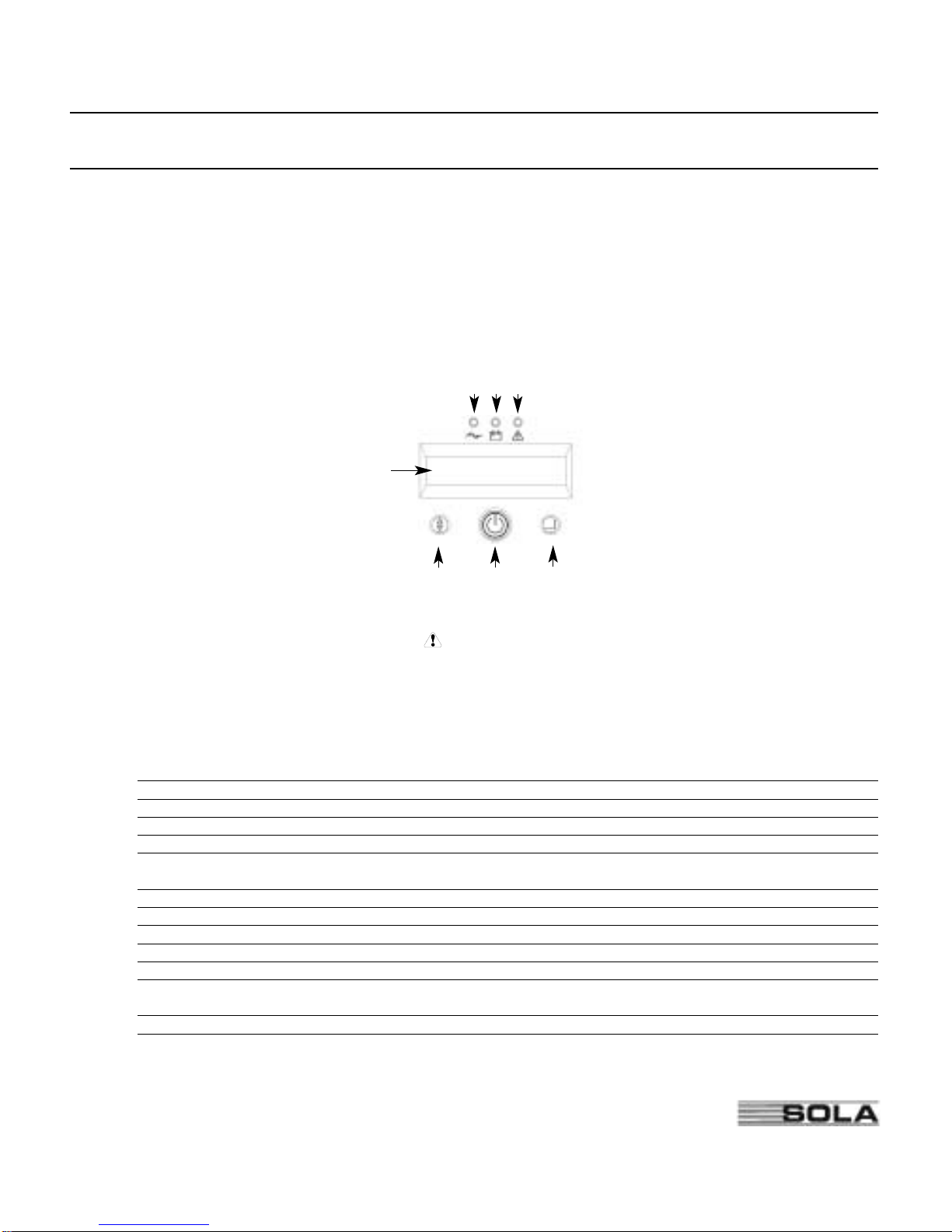
3Start the SOLA 625 by pressing and holding the On/Standby button (large button in the cen-
ter of the front panel) in for about one second. Note: To turn the unit on, the On/Standby
button must be pressed for about one second and for about 5 seconds to turn the unit off.
3.a. When it starts, the unit beeps once, then twice, and lights the “Power On” LED. The unit
indicates “On Delay” on the LCD and performs an internal system and battery test. Next,
the SOLA 625 applies AC output to the back panel receptacles and indicates “On Line”
on the LCD.
3.b. After 10 seconds or less, the self test is complete. The green LED will come on and
remain on. If the unit beeps, or if the green LED does not remain on even though input
power is available from the wall outlet, go to the Troubleshooting section.
4Switch off the equipment you want to protect, and plug each load into the outlets on the back
of the SOLA 625. Refer to Section 5.3 for detail on the load segment feature.
5Switch on the protected equipment, one load at a time. If the UPS beeps an alarm when you
start your equipment, the UPS may be overloaded. See the Troubleshooting section.
The LCD on the front of the UPS shows the % of load capacity that your equipment is using.
See Section 3.0 Operation for more information on checking the load %..
6The RJ-45 Surge Protection jacks will protect equipment that uses an
RJ-11 or RJ-45 connection. Plug the 10BASE-T network connection
into the surge protection jack labeled “IN” on the back of the SOLA
625. Plug the protected equipment into the surge protection jack
labeled “OUT.” Network cabling is not provided. This connection is
optional. It is not needed to use the SOLA 625.
Do not use this connection for modems or telephones
7Please fill out the warranty registration card in Section 10 and return it to your local
Invensys office.
Out In
NETWORKSURGESUPPRESSION
RJ-45 Jacks

7
SOLA Never Stops Innovating
3.0 Operation
This section describes:
• The UPS front panel • Standby mode
• Turning the UPS on and off • Diagnostic tests
• Starting the UPS on battery
3.1 UPS Front Panel
The UPS front panel indicates the UPS status and also identifies potential power problems. Figure
6 shows the UPS front panel indicators and controls.
Figure 6. UPS Front Panel
NOTE If the alarm beeps or if the indicator is on, see Table 10 in Section 9.0 to identi-
fy and correct the problem. To configure parameters through the front panel, see Section
4.0 "Configuration".
Display Mode
To view the UPS current settings, press the ↵button for one second and release. Use the ↵
button to scroll through the list of settings, which appear in the following order:
LCD Message Description
I/P VOLT= xxx.xV Input voltage.
I/P FREQ= xx.xHZ Input frequency.
O/P VOLT= xxx.xV Output voltage.
O/P FREQ= xx.xHZ Output frequency.
O/P Load = x% Approximate percentage of UPS load capacity being used
by the protected equipment.
O/P Watt= xW Output watts.
O/P VA= xVA Output VA.
O/P Cur= x.xA Output current.
BAT VOLT= xx.xV Battery voltage.
BAT CHARGE= xxx% Approximate percentage of battery capacity remaining.
BackUp Time= xxxM Approximate battery time remaining in minutes. The display
changes to seconds after one minute (Backup Time= xxxS).
CPU Version x.xx Firmware revision level.
NOTE The UPS exits Display mode automatically after five seconds if the ↵button is not pressed. To
lock the meter screen, press the ↵button until a beep is heard (3 seconds) then release it. To unlock
the display, press the button until a beep is heard then release it.
LCD Panel
Power On
Indicator Alarm
Indicator
On Battery
Indicator
Scroll
Button On/Off
Button Enter
Button

8
SOLA Never Stops Innovating
3.2 Turning the UPS On
After the UPS is connected to a power source, the fan turns on and the UPS enters Standby
mode. To turn on the UPS, press and hold the button until you hear the UPS beep (approximately
one second). The LCD briefly displays “On Delay” and the “Power On” indicator illuminates. Then
the UPS conducts a self-test, briefly displaying “On BATTERY”. If an alarm condition occurs, see
Table 10 in Section 9.0 for helpful hints.
When the self-test is complete, the LCD displays “On Line” indicating that power is available from
the UPS output receptacles.
Starting the UPS on Battery
NOTE Before using this feature, the UPS must have been powered by utility power at least
once and the batteries must be completely charged.
To turn on the UPS without using utility power, press and hold the button until you hear the
UPS beep (approximately one second). The UPS supplies power to your equipment and goes into
Battery mode. The LCD briefly displays “On Delay”, then “On Battery” and the and
indicators illuminate. When the UPS starts on battery, it does not conduct a self-test to conserve
battery power.
3.3 Turning the UPS Off
To turn off the UPS, press and hold the button until the long beep ceases (approximately five
seconds).
NOTE When you press and hold the button, the LCD displays Shutdown Pending.
The indicator turns off and the LCD briefly displays UPS OFF before going blank. The fan
continues to run and the UPS remains in Standby mode until you unplug or remove utility power
from the UPS.
3.4 Standby Mode
When the UPS is turned off and connected to a power source, the UPS is in Standby mode. The
fan continues to run and the battery recharges when necessary. The indicator is off and the
LCD panel is blank, indicating that power is not available from the UPS.
3.5 Diagnostic Tests
The UPS automatically performs a self-test when powered on and when the UPS restarts after a
power outage. The self-test monitors the UPS electronics and battery and indicates any problems
on the front panel.
A battery test is automatically performed every 30 days (720 hours) of continuous Normal mode
operation. The test lasts approximately 15 seconds and any failure is displayed on the front panel.
Both the UPS and battery tests can be performed manually (see Section 4.0 "Configuration" for
more information).

9
SOLA Never Stops Innovating
4.0 Configuration
This section describes how to reconfigure options using the Configuration mode, including: input
and output voltage and frequency, site wiring fault, and silencing the alarm.
NOTE The UPS has been factory-configured with default settings appropriate for most
installations. User configuration is not normally required.
Configuration Mode
The control buttons ( and ↵) are used to modify the UPS configuration. Figure 7 shows the
front panel and Table 1 explains the corresponding options.
NOTE The UPS can be configured while in Battery mode. If the UPS switches to battery power
while in Configuration mode, the UPS exits Configuration mode and indicates Battery mode on
the front panel.
1. Press the button for one second to enter Configuration mode.
The LCD displays the first configuration parameter (see Table 1).
2. Press the button to scroll through the parameters.
NOTE The UPS exits Configuration mode automatically after five seconds if a selection
has not been made.
3. Press the ↵button to select the parameter.
4. Press the button to scroll through the options for the selected parameter; press the ↵
button to select the option.
You may be prompted to save the selection; press the ↵button to save. Other options are
saved automatically. See Table 1 for more detail.
5. To exit Configuration mode at any time, do not press any buttons for five seconds.
The UPS returns to Normal mode and displays On Line.
Figure 7. Using the Configuration Mode
Press the Enter button to select a
parameter. Also press the Enter
button to select an option and to
save the setting.
Press the Scroll button to enter
Configuration mode. Also press
to scroll to the next option.
LCD Panel
Power On
Indicator Alarm
Indicator
On Battery
Indicator
Scroll
Button On/Off
Button Enter
Button

10
SOLA Never Stops Innovating
Table 1. Configuration Mode Parameters
Parameter LCD Message Description Default Settings
Output Voltage Setting O/P V Setting To change the output voltage
• Select 208, 220, 230, or 240V for 240V models. For 240V models:
You are prompted to save this setting. O/P V= 230V
Input Voltage Tolerance I/P Bypass Set Select the input voltage tolerance range before the UPS I/P Tol=+10%/-15%
goes to Battery mode: ±10%, +10%/-15%, or +15%/-20%.
You are prompted to save this setting.
Input Frequency I/P F Setting The factory-default is 50 or 60 Hz, ±5%. Select ±2% for Freq Tol.=+/-15%
a narrower frequency range. Select ±7% for a wider
frequency range.
You are prompted to save this setting.
High-Efficiency Mode HE Mode Setting Select whether High-Efficiency mode is On or Off. If HE Mode Off
enabled, you must also select the input voltage range:
±10% or ±15%.
While operating in High-Efficiency mode, the UPS
transfers to utility power when: 1) the input voltage is
outside ±10% or ±15% from nominal; 2) the input
frequency is greater than ±3%; or 3) the input line is
not available.
You are prompted to save this setting. If the setting is not
allowed, the LCD shows “I/P out limit” which means the
input voltage or frequency is not suitable.
Free Run Mode Free Run Mode Select whether Free Run mode is On or Off. If enabled, Free Run On
you must also select Bypass Disable or Bypass Enable. (Bypass Disable)
This selection defines how your UPS runs when the input
frequency (from the utility) is outside the selected frequency
tolerance (set via the I/P F Setting, above), but is inside the
maximum frequency limits the UPS can accept before
switching to Battery mode.
For example: If your 50 Hz UPS is set to the factory default
window of ±5% before the UPS starts regulating the frequency.
• The output frequency tracks the input frequency exactly from
47.5 to 52.5 Hz.
• If input frequency is between 45 and 65 Hz, the output
frequency is regulated by the UPS to exactly 50 Hz (±0.5 Hz).
You are prompted to save this setting.
Alarm Silence Alarm Silence Select whether Silence is On or Off. If enabled, the UPS Silence Off
silences the alarm for an existing fault. If the UPS status
changes, the alarm beeps, overriding the previous alarm
silencing. The alarm does not silence if there is a low
battery condition.

11
SOLA Never Stops Innovating
Table 1. Configuration Mode Parameters (cont.)
Parameter LCD Message Description Default Settings
Manual Battery Test Manual Bat Test To initiate a manual battery test, press the ↵button Battery Test
twice when “Manual Battery Test” is displayed on the
LCD. During the test the LCD displays ON BATTERY.
The UPS resets the automatic timer after a manual
battery test. The LCD displays “Battery not charged”
when UPS test is requested but the battery is not
fully charged.
Manual UPS Test Manual UPS Test To initiate a manual UPS self-test, press the ↵button UPS Test
twice. During the test, the LCD displays ONBATTERY.
Site Wiring Fault Alarm Site Fault Set Select Enable or Disable. When enabled, the alarm sounds Detect Enable
when the ground connection is missing or the line and
neutral wires are reversed in the wall outlet.
Modem Support Modem Support This parameter is reserved for future use, and should not No Modem Support
be modified by the user.
Number of Extended Bat Pack Num Set Select the number of EBMs connected to the UPS: Extern Pack: 0
Battery Modules • For 700-1500 VA models, select 0 through 2
• For 2000-3000 VA models, select 0 through 5.
You are prompted to save this setting. Refer to the
documentation that came with your battery pack for
more information.
Communications Lock- COM Control For greater levels of security, users may choose to have Enable
out Cmds the UPS disregard shutdown commands that come from
the power management software or other communication
sources.
• When disabled, the UPS does not accept a shut down
command via the communication port, USB port, or
communication slot adapter.
• When enabled, the UPS operates normally in response
to external commands.
You are prompted to save this setting.
Load Segment Control Load Group Set Allows manual control of load segments (see “Load Group 1On 2On
Segments” Section 5.3)
By repeatedly pressing the scroll button, the individual
load segments can be turned on and off.
CAUTION To prevent the unintentional shutdown of
specific load segments, confirm your selection before
pressing the ↵button.
Manual Bypass Manual Bypass This parameter is used to manually place the UPS in Bypass OFF
GO Bypass mode.
Configuration Mode Config Mode Set This parameter is reserved for future use, and should not EscapeConfigMode
Setting be modified by the user. The setting may be toggled
between EscapeConfigMode and Enter ConfigMode. 5.0
It should always be set to EscapeConfigMode.

12
SOLA Never Stops Innovating
5.0 Additional UPS Features
This section describes:
• Inverter Shutdown
• Network Transient Protector
• Load segments
• Using the communication port or USB port
• Optional SOLA communication cards
5.1 Inverter Shutdown
The SOLA 625 includes a port that allows the UPS inverter to be switched off.
This feature is designed to be used with SOLA External Maintenance Bypass Switches. Refer to
the instructions provided with the switch for further information.
WARNING
The Inverter Shutdown circuit is an IEC 60950 safety extra low
voltage (SELV) circuit. This circuit must be separated from any
hazardous voltage circuits by reinforced insulation.
Figure 8. Inverter Shutdown Connector
5.2 Network Transient Protector
The Network Transient Protector, shown in “UPS Features” Section 1.0, is located on the rear
panel and has jacks labeled IN and OUT. This feature accommodates a single RJ-45 (10BaseT)
network connector.
Connect the input connector of the equipment you are protecting to the jack labeled IN. Connect
the output connector to the jack labeled OUT.
This connector should not be connected to PSTN telephone lines or equipment.
5.3 Load Segments
Load segments are sets of receptacles that can be controlled by power management software
(such as Software Suite CD), providing an orderly shutdown and startup of your equipment. For
example, during a power outage, you can keep key pieces of equipment running while you turn off
other equipment. This feature allows you to save battery power. See your Software Suite manual
for details.
The individual load segments can also be turned on and off through the front panel (see Section
4.0, Table 1).
Section 1.0 “UPS Features” shows the load segments for all plug/receptacle models.
Pin 1Pin 2Pin 1Pin 2

13
SOLA Never Stops Innovating
5.4 Communication Port
To establish communication between the UPS and a computer, connect your computer to the UPS
communication port using the supplied communication cable.
When the communication cable is installed, power management software can exchange data with
the UPS. The software polls the UPS for detailed information on the status of the power environ-
ment. If a power emergency occurs, the software initiates the saving of all data and an orderly
shutdown of the equipment.
The pin functions are described in Table 1.
Table 2. Communication Port Pin Assignment
Pin Number Signal Name Function Direction from the
Multi-Port Module
1 Low Batt Low Battery relay contact Out
2 RxD Transmit to external device Out
3 TxD Receive from external device In
RS-232 low Conditional Power Off: In absence In
level signal of AC power, output is turned off
for>0.4 until normal AC power returns
seconds
4 - No Connection -
5 GND Signal Ground -
6 - No Connection -
7 - No Connection -
8 AC Fail AC Fail relay contact Out
9 Power Source +V (8 to 24 volts DC power) Out
USB Port
The UPS is also equipped with a USB communication port. Either the DB-9 communication port or
the USB port may be used to monitor the UPS; however, they cannot operate simultaneously.
Refer to the power management software instructions for using the USB port.
5.5 Communication Slot
The SOLA 625 UPS has a communication slot that allows quick installation of the optional
SNMP/Web adapter or future communication interfaces. These interface adapters extend the
capabilities of the SOLA 625 system to provide compatibility with network and remote monitor-
ing/management systems.
5.6 SNMP/Web Adapter
This adapter provides the SOLA 625 system with its own ethernet network connection, allowing it
to be remotely monitored and controlled via industry-standard internet browsers. The HTML inter-
face enables UPS monitoring and management from anywhere on the internet or within your
intranet. In addition, third-party Simple Network Management Protocol (SNMP) software packages
may also be used to communicate remotely with the SOLA 625 system.

14
SOLA Never Stops Innovating
5.7 Relay Card
This interface provides true relay contact output to peripheral devices. Outputs are user-selectable
as normally open or normally closed.
Table 2. Relay Card (AS/400) Pin Assignment
Pin Number Signal Name Definition Direction
1 - Isolated common to pins 2 & 3 -
2 Line OK Relay contact; closed to pin 1 -
3 Line Failure Relay contact; closed to pin 1 -
4 - Isolated common to pins 5 & 6 -
5 Battery Normal Relay contact; closed to pin 4 -
6 Battery Low Relay contact; closed to pin 4 -
7 - Isolated common to pins 8 & 9 -
8 UPS Alarm Relay contact; closed to pin 7 -
9 UPS On/OK Relay contact; closed to pin 7 -
10 - Isolated common to pins 11 & 12 -
11 UPS Online/Inverter Relay contact; closed to pin 10 -
12 UPS on Bypass Relay contact; closed to pin 10 -
13 +12VDC Signal supply +12VDC Out
14 Signal GND Signal ground - Common -
15 UPS Shutdown Minimum 5 seconds high level In
signal (+12VDC) to perform
shutdown according to following
Relay Card Jumper settings:
JP1 (default) JP2 JP3
UPS Normal - No response Go to bypass mode,
back online when
shutdown pins opened
UPS on Battery Output off after Immediate output off Immediate output off
120 sec. Back online UPS shutdown in UPS shutdown in
on resumption of AC 12 seconds 12 seconds
power
6.0 Installing Lansafe Software
Your UPS is supplied with a CD-ROM and communication cable to install and operate Lansafe power man-
agement software. To install Lansafe on your computer, follow the instructions enclosed with the Software
Suite CD-ROM.

15
SOLA Never Stops Innovating
7.0 Replacing the Batteries
The SOLA 625 batteries are user-replaceable and can be replaced while the SOLA 625 has AC input
applied and powers the loads. This means that, if necessary, you can replace the batteries while the UPS
is running. Before you replace the batteries, make sure that you read the safety information below.
Note: If you have a power outage while you are replacing the batteries, the UPS will not be able to run
on battery power and your protected equipment will shut down.
CAUTION!
The batteries used in the UPS and battery pack can produce dangerous voltage and high
current. Therefore, the batteries may cause severe injury if their terminals contact a tool or the
UPS cabinet. Be very careful to avoid electrical shock and burns from contacting terminals
while you replace the batteries.
Batteries contain caustic acids and toxic materials and can rupture or lead if mistreated.
Remove rings and metal wristwatches or other jewelry. Do not carry metal objects in your
pockets: these objects could fall into the UPS.
Never allow any tool to contact both a battery terminal and the UPS cabinet or another
battery terminal. Do not lay tools or metal parts on top of batteries.
To ensure continued superior performance of your UPS and to maintain proper charger
operation, you must replace the UPS batteries with the same number and type of batteries.
These batteries must be the same type as the original batteries: valve-regulated, low
maintenance. The replacement batteries should have the same voltage and ampere-hour rat-
ing as the original batteries.
Assume that old batteries are fully charged. Use the same precautions you would use when
handling a new battery. Do not short battery terminals with a cable or tool! Batteries contain
lead. Many areas have regulations about disposing of used batteries. Please dispose of old
batteries properly. DO NOT dispose of batteries in a fire because the batteries could explode.
Do not open or mutilate batteries. Released electrolyte is harmful to the skin and eyes. It may
be toxic.
This equipment may produce ozone. Take precautions to ensure that the concentration of
ozone is limited to a safe value (0.1 ppm {0.2 mg / m} calculated as an 8-hour time-weighted
average).

16
SOLA Never Stops Innovating
7.1 How to Replace Internal Batteries
Use the following steps to replace the internal batteries:
1. Using caution not to put stress on the LCD display cable, pull
the top of the front panel forward. Release the spring latches at
the bottom of the front panel and remove it, placing it to the
side of the UPS.
2. Unscrew the metal battery
cover (2000VA model
shown).
3. Pull the battery out onto a flat, stable surface (2000VA
model shown)
4. Remove the old battery. See “Recycling the Used
Battery” for proper disposal.
5. Install the new battery.
6. Reinstall the metal battery cover and front panel.
7.2 Recycling the Used Battery
Contact your local recycling or hazardous waste centre for information on proper disposal of the
used battery.
WARNING
• Do not dispose of the battery or batteries in a fire. Batteries may explode. Proper dispos-
al of batteries is required. Refer to the local codes for disposal requirements.
• Do not open or mutilate the battery or batteries. Released electrolyte is harmful to the
skin and eyes. It may be toxic.
CAUTION
Do not discard the UPS or the UPS batteries in the trash. This product contains sealed lead-acid
batteries and must be disposed of properly. For more information, contact your local recycling or
hazardous waste centre.

17
SOLA Never Stops Innovating
8.0 Specifications
Invensys reserves the right to change specifications without prior notice.
This section provides the following specifications for the SOLA 625 models:
• Electrical input and output
• Environmental and safety
• Weights and dimensions
• Battery
Table 4. Electrical Input 240V Models
Nominal Voltage 240V default; 208, 220, 230, 240V selectable
Voltage Range 160-276V for 208, 220, 230, 240V nominal
Nominal Frequency 50/60 Hz, ±5% user-selectable
Noise Filtering MOVs and line filter for normal and common mode noise
Connections 06250700A: 10A, IEC-C14 input connector
06251000A: 10A, IEC-C14 input connector
06251500A: 10A, IEC-C14 input connector
06252000A: 10A, IEC-C14 input connector
06253000A: 16A, IEC-C20 input connector
Table 5. Electrical Output
240V Models
Power Levels 06250700A: 700 VA, 490W
(rated at nominal inputs) 06251000A: 1000 VA, 700W
06251500A: 1500 VA, 1050W
06252000A: 2000 VA, 1400W
06253000A: 3000 VA, 2100W
Regulation Nominal output voltage ±2%
(Normal mode)
Regulation Nominal output voltage ±3%
(Battery mode)
Voltage Waveform Normal mode: Sine wave; <5% THD with full PFC and
nonlinear load
Output Connections 06250700A: (4) Australian 10A
06251000A: (4) Australian 10A
06251500A: (4) Australian 10A
06252000A: (5) Australian 10A
06253000A: (5) Australian 15A
Table of contents
Other Sola UPS manuals
Popular UPS manuals by other brands

Uninterruptible Power Supplies
Uninterruptible Power Supplies Minipower Plus Rack user manual

Minuteman
Minuteman ETR550LCD user manual

CyberPower
CyberPower PR1500 user manual

PowerWalker
PowerWalker VFI 1000R/1U manual

Tripp Lite
Tripp Lite SmartPro AG-0021 owner's manual

PowerWalker
PowerWalker 650 SH quick start guide