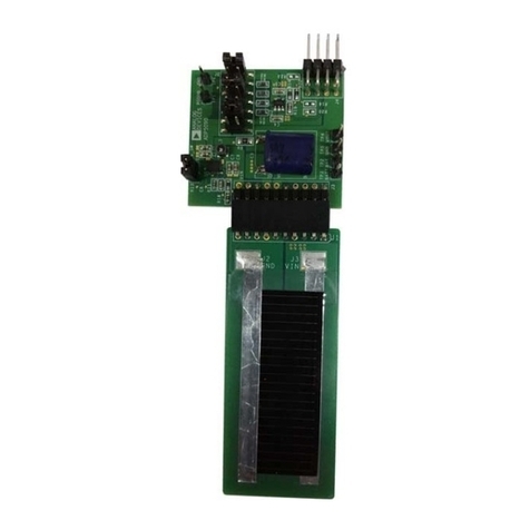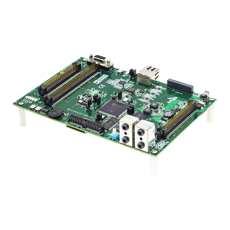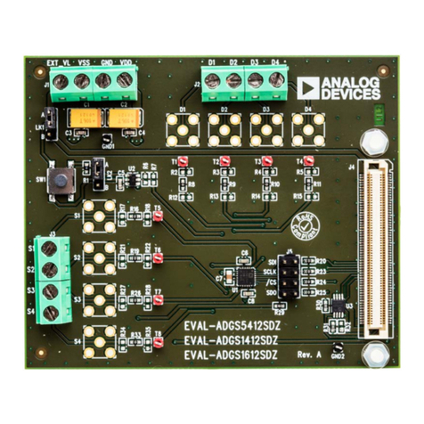
UG-1308 EVAL-ADuCM355QSPZ Evaluation Board
Rev. A | Page 2 of 24
TABLE OF CONTENTS
Features.............................................................................................. 1
Equipment Needed........................................................................... 1
Documents Needed.......................................................................... 1
Software Needed............................................................................... 1
General Description ......................................................................... 1
Evaluation Board Photograph ........................................................ 1
Revision History ............................................................................... 2
Power Configurations...................................................................... 4
MicroUSB Direct Power via P4 and ADP7158 LDO
Regulator ....................................................................................... 4
Direct 3.3 V Power via the AVDD and DVDD Connectors.. 6
Power via USB from 8-Pin DEBUG Connector (P27)............ 6
Power via External 5 V Supply to 2-Pin Connector (P37) ..... 6
Connecting an Electrochemical Sensor......................................... 7
Getting Started with the Tool Chain ............................................. 8
Downloading the Integrated Development Environment
(IDE) .............................................................................................. 8
Installing the ADuCM355 Support Package ............................ 8
Running a GPIO Example in IAR Embedded Workbench ....8
Running a GPIO Example in Keil μVision............................. 11
Application Examples.................................................................... 13
Cyclic Voltammetry Example .................................................. 13
EIS Example ................................................................................ 14
Chronoamperometry Example ................................................ 14
DC Current Example................................................................. 15
4-Lead Electrochemical Sensor Example................................ 16
Connecting an External Gain Resistor Across the High Speed
TIA ............................................................................................... 17
AFE Die Watchdog Timer Example........................................ 17
ADuCM355 System Calibration .................................................. 18
High Speed TIA Gain Resistor Calibration............................ 18
Low Power TIA0/TIA1 Gain Resistor Calibration ............... 20
Mass Erasing a Device Not Responding to SWD Commands. 22
Ordering Information.................................................................... 23
Bill of Materials .......................................................................... 23
REVISION HISTORY
4/2021—Rev. 0 to Rev. A
Changes to Features Section, Equipment Needed Section,
Software Needed Section, and General Description Section ..... 1
Deleted MicroUSB Connector, P4 Setup Section Heading ........ 4
Changes to Power Configurations Section, MicroUSB Direct
Power via P4 and ADP7158 LDO Regulator Section, and
Figure 2 Caption............................................................................... 4
Changes to Direct 3.3 V Power Via the AVDD and DVDD
Connectors Section, Jumper Setup with Direct 3.3 V Connection
Section, Power via USB from 8-Pin Debug Connector (P27)
Section, Jumper Setup with Power via USB Section, Figure 5
Caption, and Power via External 5 V Supply to 2-Pin Connector
(P37) Section ..................................................................................... 6
Changes to Connecting an Electrochemical Sensor Section...... 7
Deleted Figure 8; Renumbered Sequentially ................................ 7
Changed Getting Started with the Tool Chain Section to
Getting Started with the Tool Chain Section ............................... 8
Changes to Downloading the Integrated Development
Environment (IDE) Section, Installing the ADuCM355 Support
Package Section, Running a GPIO Example in IAR Embedded
Workbench Section, and Project Folder Structure Section........ 8
Replaced Figure 9 ............................................................................. 9
Changes to Compiling and Running Firmware Section and
Figure 11 Caption........................................................................... 10
Replaced Figure 10 and Figure 12................................................ 10
Replaced Figure 14 ......................................................................... 11
Added Running a GPIO Example in Keil μVision Section,
Figure 15, and Figure 16; Renumbered Sequentially ................ 11
Deleted Figure 19 ........................................................................... 11
Added Figure 17 to Figure 19 ....................................................... 12
Changes to Application Examples Section, Cyclic Voltammetry
Example Section, and Figure 22 Caption.................................... 13
Added Figure 21 ............................................................................. 13
Changes to Figure 23 Caption, EIS Example Section, and
Chronoamperometry Example Section ...................................... 14
Replaced Figure 23 and Figure 25................................................ 14
Added Figure 24 ............................................................................. 14
Replaced Figure 28 and Figure 29................................................ 15
Changes to Figure 28 Caption and DC Current
Example Section ............................................................................. 15
Changes to 4-Lead Electrochemical Sensor
Example Section ............................................................................. 16
Added Figure 30 ............................................................................. 16
Moved Connecting an External Gain Resistor Across the High
Speed TIA Section, AFE Watchdog Timer Example Section,
and Figure 32 .................................................................................. 17
Changes to AFE Die Watchdog Timer Example Section ......... 17
Added ADuCM355 System Calibration Section ....................... 18
Moved High Speed TIA Gain Register Calibration Section..... 18
Deleted Figure 29 ........................................................................... 18
Changes to High Speed TIA Gain Resistor
Calibration Section......................................................................... 18
Deleted Figure 33 ........................................................................... 18
