ANATEL Novus RHT-Air User manual

NOVUS AUTOMATION 1/10
RHT-Air
WIRELESS DEVICE FOR TEMPERATURE,
RELATIVE HUMIDITY AND DEW POINT
INSTRUCTIONS MANUAL V2.0x A

NOVUS AUTOMATION 2/10
1INTRODUCTION
RHT-Air comes with a high accuracy and stability sensor to measure
temperature, relative humidity, and dew point. Because it operates with a
microprocessor, it can be fully configured through its USB and IEEE 802.15.4
interfaces. DigiConfig software enables for all the device resources to be
configured.
RHT-Air can be configured to display the temperature, the relative humidity
and the dew point and can display up to two of them simultaneously.
RHT-Air must be connected to an AirGate-Modbus so that it can access its
parameters when in operation. AirGate-Modbus will provide Modbus RTU
access to its registers over the IEEE 802.15.4 wireless network.
In addition to battery operation with typical range of 1 year (for an update
interval higher than 60 seconds and stable connection in an IEEE 802.15.4
network), RHT-Air can also be powered by an external source.
1.1 IDENTIFICATION
The following elements appear in the front part of the device:
Figure 1 –RHT-Air main screen
Communication Indicator (COM): It signals that the device is receiving data
from the Modbus network.
Button (Programming): This button is used to configure the Modbus
address, the Update Interval and to screen changes.
Temperature: Environment temperature measured by the device.
Relative Humidity: Relative humidity measured by the device.
Figure 2 –RHT-Air second screen
Communication Address: Programmed value to identify the Modbus
network device. Programmable between1and 246.
2SPECIFICATIONS
Operating
temperature -10 °C to 70 °C (14 °F to 158 °F)
Sensor
measurement
range
Temperature: -40 °C to 100 °C (-40 °F to 212
°F)
Relative Humidity (RH): 0.0 to 100.0 % RH
(No condensation)
Dew Point: -40 °C and 100 °C (-40 °F to 212 °F)
Measurements
Accuracy
See Figure 3.
Note: It is possible to perform an Offset
adjustment using the DigiConfig
software to
reduce the measurement error found.
Response time
(Sensor)
Temperature: Up to 30 s with air movement at 1
m/s.
Measurements
Accuracy
Humidity: Up to 8 s with air movement at 1 m/s
(20 to 80% RH).
Interval between
updates
Configurable between 15 seconds and 10
minutes (600 s).
Power supply
Power supply: 12 Vcc to 30 Vcc.
Consumption < 100 mA.
Internal battery (included): Lithium 3.6 Vcc 1/2
AA 0,80 Ah. Omnicell manufacturer
(ER14250HD model) or EEMB manufacturer
(ER14250M model).
Estimated battery
life
Typical: 1 year - Update interval greater than 60
seconds.
Connections
•Internal USB Device (micro-B) for
configuration and firmware update.
•RP-SMA female connector
for antenna
(included).
•M12 connector for external power (cable
included).
Communication Modbus RTU about Wireless IEEE 802.15.4
protocol (AirGate-Modbus necessary).
Wireless
•Maximum transmission power of 25,11 mW
(14 dBm).
•Maximum Range: 500 meters line-of-sight in
open field.
•Data rate: RF 250 Kbps.
•Receptor sensibility - 92 dBm.
•Operation band: ISM 2.4 GHz.
•DSSS Technology (Direct Sequence Spread
Spectrum).
•OQPSK Modulation (
Offset Quadrature
Phase Shift Keying).
•15 operation channels.
•AES-CBC-128 (Adv
anced Encryption
Standard).
Housing Polycarbonate.
Protection IndexIP40
Dimensions
60 x 70 x 35 mm.
Antenna measurement: 105 mm.
Sensor measurement: 37,2 mm.
Weight
171 grams / 40 grams (cable).
Configuration
software
DigiConfig – Configuration software for
Windows.
Certifications CE, FCC, ANATEL (00172-13-07089).
Contains FCC ID: 2AXVWBAIRR-NOVUSAIR.
Electromagnetic
compatibility
EMC: EN61326-1:2006 CISPR11/EN55011,
EN61000-4-2, EN61000-4-3, EN61000-4-4,
EN61000-4-6, EN61000-4-8

NOVUS AUTOMATION 3/10
2.1 ACCURACY OF MEASUREMENTS AND OPERATIONAL LIMITS OF SENSORS
Figure 3 –Accuracy of the humidity and temperature measurement
3MECHANICAL INSTALLATION
RHT-Air was designed to be attached to walls. By removing the device
cover, users will have access to two molding holes of the base, as shown in
Figure 4.
The device should be attached with the sensor capsule facing
downwards to ensure accuracy and the specified level or protection.
Figure 4 –RHT-Air mounting holes and measures
Figure 5 –RHT-Air measurements
4CONFIGURATION
4.1 CONFIGURATION VIA USB INTERFACE
Initially, the first configuration must be done through USB interface.
•Remove the four set screws of the front panel of the RHT-Air device,
taking the necessary precaution not to apply force on the internal
connector of the electronic circuit.
Figure 6 –RHT-Air screws
•To configure the USB interface, connect the cable as shown in the
following figure. The external power cable is not used during the
configuration because the device will be powered by the USB interface.
Figure 7 –USB connector
5ELECTRICAL INSTALLATION
5.1 EXTERNAL POWER SUPPLY CONNECTION
Figure 8 below shows RHT-Air necessary electrical connection.
Terminals 1 and 2 are to be used in the electrical connection and
terminals 3 and 4 are not used.
1 - VCC Power supply Black wire
2 + VCC Power supply White wire
3
Not used
Blue wire
4 Not used Brown Wire
Disconnect the power supply while the device is opened.

NOVUS AUTOMATION 4/10
Figure 8 –Electrical connection
M8 4-pin female power supply cable.
For replacement,
consult commercial department.
5.1.1 INSTALLATION RECOMMENDATIONS
•Conductors of small electric signals must be separated from activation
conductors or higher current or power in the system plan. If possible, in
grounded conduits.
•The instrument supply must come from a network proper for
instrumentation.
•In control and monitoring applications, it is essential to consider what
may happen when any part of the system fails.
•It is recommended to use RC FILTERS (47 Ωand 100 nF, series) in
parallel with coils of contactors and solenoids, etc.
5.2 BATTERY POWER SUPPLY
RHT-Air can be supplied by an internal battery whenever the device is not
energized by the electrical grid. It can be a power backup, being
automatically used when the power from the external power source is not
present.
RHT-Air is shipped with a battery insulation film. Therefore, it must be
removed before first use. When the device is not in use, remove the battery
or put the insulation film on it to avoid the battery premature death.
The following step-by-step will guide you on how to proceed to power the
device using the battery.
•Remove the four screws from the RHT-Air front panel. Be careful not to
force the internal connector of the electronic circuit.
Figure 9 –RHT-Air screws
•After removing the front panel, remove the insulation film from the
battery.
Figure 10 –Insulation film from the battery
5.2.1 REPLACING THE INTERNAL BATTERY
It is possible to check the battery charge through register “29”. A fully charged
battery typically has a power above 3.6 V. As you use the RHT-Air, the power
of the battery will gradually decrease.
It is recommended to periodically check the value of the “29” register. When
it reaches values below 3.3 V, a battery change must be scheduled (this
register may present a measurement error of up to 5 %).
Note: Even when the power is below 100 %, the device will operate normally.
The only suitable replacement battery for this device is:
Omnicell manufacturer (ER14250HD model) or EEMB
manufacturer (ER14250M model).
•Remove the four molding screws of the front panel, taking the necessary
precaution not to apply force on the internal connector of the electronic
circuit. After removing the front panel, replace the battery, taking the
necessary precaution not to touch the electronic circuit.
Figure 11 –Battery replacement
•Insert a new battery and replace the front panel carefully, placing the
four molding screws.
Figure 12 –Inserting the battery
5.2.2 BATTERY LIFE
The battery is estimated to last for over a year for update intervals higher than
60 seconds. There is a fine line between its life and how the device is used.
The lower the sensor reading interval, the shorter it will last, as it may. In the
worst-case scenario, last for 30 days only.
To save battery energy, you must put as much time as possible between
upgrades. The transmission power level for communicating with the AirGate-
Modbus network also influences the battery life. Thus, the device must be
configured to operate at minimum power and as close as possible to an
AirGate-Modbus network as possible.
In addition, to achieve autonomy over one year, it is necessary to use it in a
network where there is an AirGate-Modbus, stable and available for pairing.
Every need to repair with the network significantly degrades the battery.
In a situation where RHT-Air is well installed, it is possible that the battery lasts
more than 2 years.
Remove the battery or insert the insulation film when the
device is not in use. Leaving the powered device out of
range of a Wireless network will cause the device to
continually attempt to pair, which may lead to premature
battery death.

NOVUS AUTOMATION 5/10
6CONFIGURATION / OPERATION
DigiConfig is a Windows software used for configuring RHT-Air. To install
it, please run the file “DigiConfigSetup.exe”, available in our website
www.novusautomation.com.
DigiConfig comes with an unabridged help tutorial, containing all the
necessary information for you to use it. If you want to use help tutorial, start
the application, and select the Help menu or press F1.
Check our website for get the DigiConfig installer and the additional manual
guides.
Users will receive the fully calibrated adjustment-free device. The original
configuration is shown below:
Addr (Communication address) = 246
Time (Update interval) = 60 s
To configure it for the first time, it is necessary to remove the front cover and
connect it to a computer through a mini-B USB cable. The initial configurations
for wireless are described as follows:
PAN ID (Network Identifier) = 22350 (0x574E)
RF Power (Power Level) = 0 dBm
6.1 RHT-Air SCREENS
Indication screen of the values measured in the device:
1ª Screen: Main
To configure the communication parameters, you should press the button
(for about 5 seconds) until it starts to blink. Release it and press it
again to expand it. When the expected value appears, release the button,
and wait until the screen stops blinking (for about 10 seconds). If you want to
move on to the following screens, press the button .
Modbus Address configuration screen: Sets the address of the module on
the Modbus network. Values between 1 and 246.
2ª Screen: Modbus Address
Time configuration screen: Sets the update interval in seconds.
3ª Screen: Update interval
Mode configuration screen: Sets the indication mode.
4ª Screen: Indication mode
CODE DESCRIPTION
0 Indicates temperature and relative humidity.
1
Indicates temperature and dew point.
2 Indicates relative humidity and dew point.
3 Indicates only temperature.
Unit configuration screen: Sets which temperature unit should be used (°C
or °F).
5ª Screen: Unit
Display screens only for measured values on the device:
6ª Screen: Temperature
7ª Screen: Relative humidity
8ª Screen: Dew point
7WIRELESS COMMUNICATION
RHT-Air has an IEEE 802.15.4 wireless communication to connect to
AirGates-Modbus that has its firmware updated to a version more recent
than V1.23. The first RHT-Air configuration must be performed via the USB
interface through the DigiConfig software. In it, the necessary parameters
for communication with AirGates network should be set. After the first time it
is configured and matched with a AirGate-Modbus, RHT-Air will operate as
a Modbus RTU slave. From this moment on, all its resources can be
accessed by reading its registers anywhere in any Modbus RTU network.
Some settings can be made via the programming button .
In this section you will find the necessary information to carry out the data
readings without the use of the DigiConfig software. To ensure the correct
device configuration, use the DigiConfig software. Once configured, the
data of its inputs can be accessed by any other software with Modbus RTU
communication capability.
7.1 MODBUS COMMANDS
The following Modbus RTU commands (functions) are implemented. For
further information on each one of these functions and on the Modbus
protocol in general, go to www.modbus.org.
READ HOLDING REGISTERS – 0x03
This function can be used to read a value of one or up to 42 retentive
registers, as per the Retentive Registers Table.
WRITE HOLDING REGISTERS – 0x06
This function can be used to write in a retentive register, as per the
Retentive Registers Table.
7.2 DESCRIPTION OF SOME REGISTERS
Once RHT-Air meets an AirGate-Modbus and is matched, this AirGate will be
last published by RHT-Air. Therefore, when the Master of the Modbus network
requires that the RH-Air address be read, the response is sent immediately
and the expiration of this publication can be checked through register 30, which
shows how long it has been since the last publication.
REGISTER 6 – PAN ID
Common identifier for each IEEE 802.15.4 wireless network. All devices on
the same network (AirGates-Modbus and RHTs-Air) must be configured
with the same PAN ID.
REGISTER 7 – ENCRYPTION
This register should be used to enable or disable the use of encryption. If it
is enabled, the encryption key should be the same used for all device
configured with the same PAN ID.

NOVUS AUTOMATION 6/10
REGISTER 16 – POWER LEVEL
According to the variations presented in the table below, the power level can be
adjusted as needed. The higher the power set, the greater the range and the
greater the consumption. It is suggested that the lowest value possible be
configured, if RHT-Air is not able to communicate with the AirGate-Modbus, it will
automatically increase the transmission power gradually, until it is able to
communicate with AirGate-Modbus or reach the highest configurable limit. It may
be that this register is configured with a value, and, after some time, this value
may be altered to adjust to a communicable power.
CODE POWER LEVEL
0 0 dBm
1
2 dBm
2 4 dBm
3 6 dBm
4
8 dBm
5 10 dBm
6 12 dBm
7
14 dBm
REGISTER 27 – OPERATION CHANNEL
It indicates the operation channel in which the device is operating in the
network. It may vary from 11 to 25, in that every channel is equivalent to one
frequency of operation. The network will always operate on the channel with
less interference among all the 15 possible ones.
CHANNEL
OPERATION FREQUENCY
11 2405 MHz
12 2410 MHz
13
2415 MHz
14 2420 MHz
15 2425 MHz
16
2430 MHz
17 2435 MHz
18 2440 MHz
19 2445 MHz
20 2450 MHz
21 2455 MHz
22 2460 MHz
23 2465 MHz
24 2470 MHz
25 2475 MHz
REGISTER 28 –LINK QUALITY INDICATOR
It serves to inform the quality of the reception link of the connection between the device and the AirGate-Modbus with which it is matched. This value is obtained by
measuring the power of the last package received. This power is measured in dBm, which is a logarithmic power unit in mW. The LQI may vary from -100 dBm (worst
reception quality) to -15 dBm (best reception quality).
For devices operating in ideal environments where there are no obstacles and no electromagnetic interference, the LQI will behave in a way close to the graph below,
where the comparison between different power levels is performed for the distance versus LQI ratio.
Figure 13 –Distance x LQI relation for several powers
The table below lists the values obtained in the LQI reading with the evaluation
of signal quality. This information can be viewed more intuitively in the
DigiConfig Diagnostics tab.
REGISTER VALUE QUALITY ICON
0 USB-connected
device
-15 to -60 Great
-60 to -70 Very Good
-70 to -80 Good
-80 to -90 Regular
-90 to -100 Bad
NOTE: The model described in the graphic takes in consideration the propagation
channel only. LQI may vary due to several factors, such as due to peripheral obstacles
like trees, buildings and hills that interfere in the propagation channels as explained by
the Fresnel Zone phenomenon.

NOVUS AUTOMATION 7/10
REGISTER 29 – BATTERY POWER
It has the value of measuring the voltage level of the battery in engineering
unit. The decimal point is fixed in three houses. The value is without the
point and must be predicted by the reading software. Reading the battery
voltage may show an error of up to 5 %.
Typically, a battery with 100 % of its load has voltage above 3.6V.
Depending on the use of RHT-Air, the battery will gradually decrease
voltage. It is recommended to periodically check the value of this register so
that, when it reaches values below 3.3 V, a battery change is scheduled.
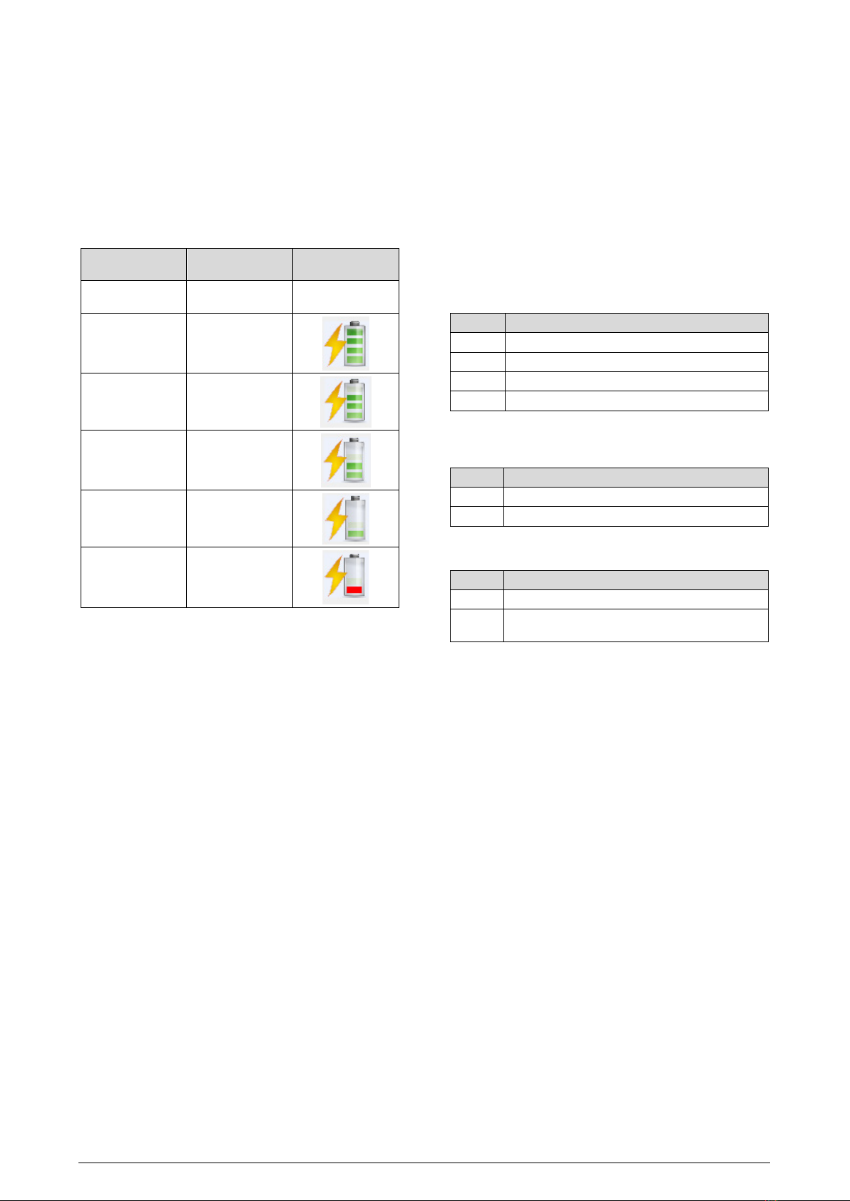
Checking the battery capacity can be done using the Diagnostics tab of the
DigiConfig software, which will display an icon. The evaluation of battery
capacity can be performed according to the criteria presented in the table
below:
REGISTER VALUE BATTERY
CAPACITY ICON
0 USB-connected
device.
3500 to 3700 Great
3400 to 3500 Very Good
3300 to 3400 Good
3200 to 3300
Average – Get ready
to replace your
battery.
Lower than 3200
Bad – Replace the
battery as soon as
possible.
NOTE 1: Even when the power is below 100 %, the device will operate normally.
NOTE 2: The gradual failure of the battery power is not linear, therefore, though the device
is able to continue working under tensions below 3.0 V, when it reaches this level, there is
little left for its life, since the power will fail more quickly.
NOTE 3: While the device is being powered from an external source, you may notice a
slight rise in battery voltage. This is because the battery voltage increases whenever power
from the same battery is not being consumed.
NOTE 4: The machine operating temperature has a significant impact on the battery
capacity. Temperatures below 0 °C will typically shorten the battery life.
NOTE 5: Battery chemistry is directly affected by the ambient temperature. High
temperatures tend to raise battery voltage, as low temperatures tend to decrease
battery voltage. In both cases, autonomy is negatively affected.
NOTE 6: The update time, as well as the operating power, have a significant impact on
the battery capacity. If the device is configured for the lowest update interval, the
battery will typically last less. The same happens when the device is far from the
AirGate-Modbus with which it should be matched, needing a higher transmission
power to operate.
NOTE 7: Remove the battery or insert the insulation film when the device is not in use.
Leaving the powered device out of range of a Wireless network will cause the device to
continually attempt to pair, which may lead to premature battery death.
REGISTER 30 – LAST POLL DURATION
Every time RHT-Air publishes something on AirGate-Modbus, this register
gets a zero value. Every 100 ms, this register is increased in 1 unit to
indicate how long it has been since the last publication.
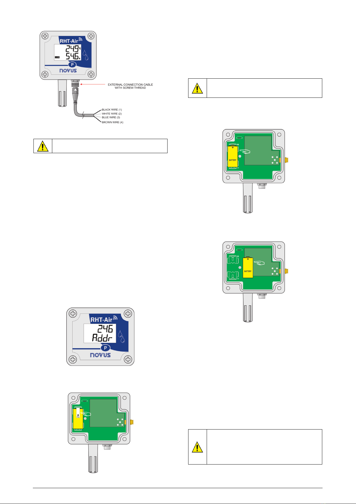
REGISTER 31 – MODBUS ADDRESS
It sets the address of the device on the Modbus network. This address
identifies the device on the Modbus network. Its configuration may range
from 1 and 247. There cannot be more than one piece of device with the
same address on the same network. RHT-Air is originally manufactured with
the address 246. When connected to a USB interface, it always responds to
Modbus functions through the address 246. When it is in operation, it always
responds through the address it was configured for in this register according
to the communication parameters of the Modbus network on which it was
installed.
REGISTER 32 – UPDATE TIME
It sets the configuration for how often the device wakes to publish
information on the AirGate-Modbus with which it is matched and update the
IHM screen.
The shorter the update time, the more recent the data available to the
master of the Modbus network will be, but the higher the energy
consumption spent, and the battery life will be proportionately shorter. On
the other hand, the higher the update time set, the lower the energy
consumption spent will be, thus providing a longer life for the battery.
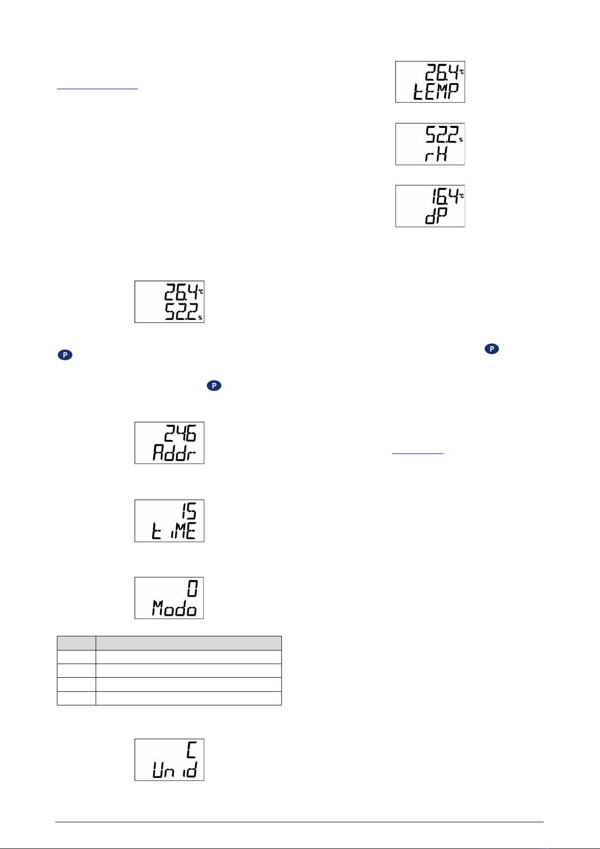
REGISTER 33 – INDICATION MODE
It sets the mode of indication of the values read on the display. The device is
originally manufactured with the indication of temperature and relative
humidity.
CODE DESCRIPTION
0 Indicates the temperature and relative humidity.
1 Indicates the temperature and dew point.
2 Indicates relative humidity and dew point.
3 Indicates the temperature only.
REGISTER 34 – CONFIGURATION OF THE MEASUREMENT UNIT
It sets the measurement unit for both temperature and dew point. The device
is originally configured in (°C).
CODE UNIT
0
°C
1 °F
REGISTER 35 – DISABLES CONFIGURATION THROUGH A BUTTON
It sets the alteration of configuration through a button.
CODE
DESCRIPTION
0 Factory default value.
1 Disables the alteration of configuration of communication
parameters via button.
REGISTER 36 – USER OFFSET FOR TEMPERATURE
It sets the users’ offset value in engineering units for temperature. The
device offset value is originally zero.
REGISTER 37 – USER OFFSET FOR HUMIDITY
It sets the users’ offset value in engineering units for relative humidity. The
device offset value is originally zero.
REGISTER 38 – ERROR VALUE
It contains the error value that is transmitted when the sensor has a problem.
The device original value is -9999.
REGISTER 39 – TEMPERATURE VALUE (°C or °F)
It contains the value of temperature measurement in an engineering unit,
including the users’ offset corrections for temperature. The decimal point is
fixed in one place. The value has no point and must be provided in the
reading software.
REGISTER 40 – RELATIVE HUMIDITY VALUE (%)
It contains the value of relative humidity measurement in an engineering
unit, including the users’ offset corrections for temperature. The decimal
point is fixed in one space. The value has no point and must be provided in
the reading software.
REGISTER 41 – DEW POINT VALUE (°C or °F)
It has the value of the measurement in an engineering unit. The decimal
point is fixed in one place. The value has no point and must be provided in
the reading software.

NOVUS AUTOMATION 8/10
HOLDING REGISTERS TABLE
The specified addresses correspond to lower-level physical addresses, as zero (0) corresponds to the PLC 40001 address. The columns reserved for Minimum and Maximum
contain a range of valid values for each parameter. The column reserved for R/W indicates whether the parameters are meant for reading and writing (R/W) or reading only (R).
ADDRESS DESCRIPTION MINIMUM MAXIMUM R/W
0
Retentive register used to manage the RHT-Air configuration stages (Used by
DigiConfig).
0 7 R/W
1
Title
-
-
R/W
2
Title
-
-
R/W
3
Title
-
-
R/W
4
Title
-
-
R/W
5
Title
-
-
R/W
6
PAN ID
0
65535
R/W
7
Encryption
0
1
R/W
8
Security keys 0 and 1
0
65535
R/W
9
Security keys 2 and 3
0
65535
R/W
10
Security keys 4 and 5
0
65535
R/W
11
Security keys 6 and 7
0
65535
R/W
12
Security keys 8 and 9
0
65535
R/W
13
Security keys 10 and 11
0
65535
R/W
14
Security keys 12 and 13
0
65535
R/W
15
Security keys 14 and 15
0
65535
R/W
16
Power Level
0
7
R/W
17
Reserved
-
-
R
18
Serial Number (word high)
0
65535
R
19
Serial Number (word low)
0
65535
R
20
Long MAC address 0 e 1
0
65535
R
21
Long MAC address 2 e 3
0
65535
R
22
Long MAC address 4 e 5
0
65535
R
23
Long MAC address 6 e 7
0
65535
R
24
Short MAC address
0
65535
R
25
Firmware version
0
65535
R
26
Device code
103
103
R
27
Operation channel
11
25
R
28
LQI – Link quality indicator
-100
-15
R
29
Battery power (V)**
0
3700
R
30
Time of last publication (100 ms)
0
65535
R
31
Modbus Address
1
247
R/W
32
Update time (s)
15
1800
R/W
33
Indication mode
0
3
R/W
34
Measurement unit configuration
0
1
R/W
35
Disables configuration through a button
0
1
R/W
36
User offset for temperature*
-100
100
R/W
37
User offset for humidity*
-100
100
R/W
38
Error value
-9999
9999
R/W
39
Temperature value (°C or °F)*
-400
1000
R
40
Relative humidity value (%)*
0
1000
R
41
Dew point value (°C or °F)*
-400
800
R
* For the abovementioned table ranges, one decimal place should be considered. Example: -100 means -10.0.
** For the abovementioned table ranges, three decimal places should be considered. Example: 3600 means 3600 V.
8SPECIAL CARE
Because it is an electronic module, the device needs some care in handling:
•When opening it for fixation, you should keep away from the electronic
circuit due to the risk of damages caused by static electricity.
•The wiring should be carefully observed.
•When closing the box, the cover must be replaced properly, thus
ensuring that it is sealed.
8.1 CARE WITH SENSORS
The calibration of the humidity sensor can be altered if it is exposed to
contaminating vapors or extreme humidity or temperature conditions for
longer periods. To speed up the calibration, do as follows:
•Remove the sensor from the capsule.
•If solid particles are deposed on the sensor, wash it with water.
•Place the sensor in an oven at 80 °C (+ -10 °C) for 24 hours.
•Place the sensor for 48 hours in a place at around 20 and 30 °C and
humidity higher than 75 % RH.
•Replace the sensor into the capsule.
8.2 BATTERY CARE
Remove the battery or insert the insulation film when the
device is not in use. Leaving the powered device out of
range of a Wireless network will cause the device to
continually attempt to pair, which may lead to premature
battery death.
The Lithium battery, due to its chemical behavior, may present some
passivation symptoms when not used for long periods of time. This can be
observed by checking the battery voltage after 2 hours of device operation.
If the battery voltage measures less than 3.5 V, then the battery may be
passivated (not necessarily worn out). If this is the case, please try applying
the following procedures to recover the battery:

NOVUS AUTOMATION 9/10
•Operate the device at its maximum power (14 dBm) and minimum
sample period (15 s).
•Let the instrument operate continuously in the above conditions for 24 h
while monitoring the battery voltage through reading register number 29
or the Diagnostic menu of the DigiConfig software.
•If the battery voltage exceeds 3.5 V, the battery can be considered
rehabilitated (depassivated). The device is then ready to use.
•In case the above does not work, please remove the battery from the
device and discharge it for 5 minutes connecting a 220 Ohm resistor
across the terminals.
•After that, you should put the battery in the device and leave it running
for about 2 hours. If the battery has a voltage above 3.5 V, it has been
undone and can operate normally.
•If after going through the above procedures the battery still fails to work
properly, please contact technical assistance for arranging battery
replacement.
IMPORTANT
The sensor used in this device may be damaged or de-calibrated if exposed
to contaminated atmospheres with chemical agents. Hydrochloric acid, nitric
acid, sulfuric acid, and ammonia in high concentrations may damage the
sensor. Acetone, ethanol, and propylene glycol may cause reversible
measurement errors.
9TROUBLESHOOTING
9.1 PROBLEMS COMMUNICATING WITH THE DEVICE VIA USB
INTERFACE OR DURING FIRMWARE UPDATE
If you have problems communicating the device via the USB interface or
there are problems during firmware update, it is recommended to perform the
following procedure to speed communication and minimize incompatibility
issues:
a. Open the Device Manager:
Figure 14 –Device Manager
b. Open the COM port setting of the device:
Figure 15 –Device Manager
c. Open advanced COM port configuration options:
Figure 16 –Port settings configuration
d. Uncheck the Use FIFO buffers option:
Figure 17 –Advanced settings
10 CERTIFICATIONS
FCC
Contains FCC ID: 2AXVWBAIRR-NOVUSAIR
This device complies with Part 15 of the FCC Rules. Operation is subject to
the following two conditions: (1) this device may not cause harmful
interference, and (2) this device must accept any interference received,
including interference that may cause undesired operation.
NOTE: This equipment has been tested and found to comply with the limits
for a Class A digital device, pursuant to part 15 of the FCC Rules. These
limits are designed to provide reasonable protection against harmful
interference when the equipment is operated in a commercial environment.
This equipment generates, uses, and can radiate radio frequency energy
and, if not installed and used in accordance with the instruction manual, may
cause harmful interference to radio communications. Operation of this
equipment in a residential area is likely to cause harmful interference in
which case the user will be required to correct the interference at his own
expense
WARNING: To satisfy FCC RF exposure requirements, a separation
distance of 20 cm or more should be maintained between the antenna of this
device and persons during operation. To ensure compliance, operations at
closer distances than this are not recommended. This device and its
antenna(s) must not be co-located or operating in conjunction with any other
This product has been tested with Wellshow AR0035EW0119N antenna.
Changes or modifications not expressly approved by the party responsible
for compliance could void the user’s authority to operate the equipment.
Canada
This Class A device complies with Canadian standard ICES-003.
Cet appareil numérique de la classe A est conforme à la norme NMB-003 du
Canada.
CE Mark
This is a Class A product. In a domestic environment, this product may
cause radio interference in which case the user may be required to take
adequate measures.
ANATEL
This device is homologated by ANATEL, in accordance with the procedures
regulated by Resolution 242/2000, and meets the technical requirements
applied.
This equipment is not subject to the protection from harmful interference and
may not cause interference with duly authorized systems.
For more information, see the ANATEL website www.anatel.gov.br.
Table of contents
Other ANATEL Measuring Instrument manuals