anatol.com
9
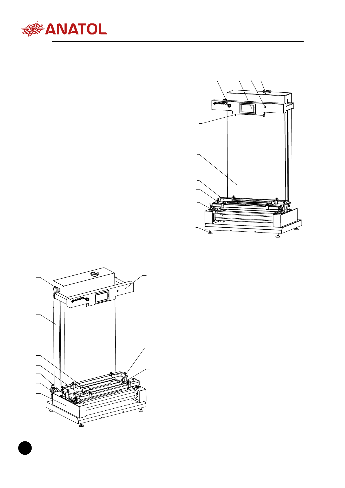
5.2 INTENDED USE
lThe Quik-Kote emulsion coating machine is intended for the automatic
application of various types of emulsion on one or two screens of the same size
simultaneously. The emulsion machine has the ability to apply emulsion on one
side of the screen, or both sides of the screen simultaneously.
Any other use of the device besides those described in this manual is strictly
forbidden. Incorrect use of the device will void the warranty.
Air supply
Power supply
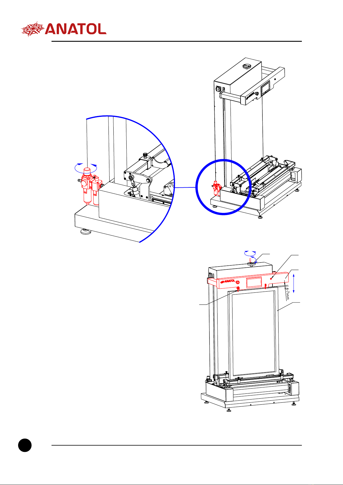
6. OPERATION
6.1 WORK SEQUENCE
Before using the emulsion coating
machine, make sure that the machine
is connected to the power source
and that the electrical cable is not
damaged or interfering with the
operation of the machine. Ensure that
the air pressure supplied meets the air
requirements specied in the technical
documentation. It is also important
to ensure that all emulsion residues
have been cleaned from the working
surfaces of the machine before use,
and that the tip of the scoop is free of
damage (burrs) as this may prevent
the machine from working properly. In
case of contamination, clean all work
surfaces before starting the machine.
If the nozzle of the ladle is damaged,
such a ladle cannot be used To turn on
the emulsion machine, turn the main
switch (20) to the ON position