PULSAR® IX-P PRESSURE BLAST CABINET Page 2
© 2019 CLEMCO INDUSTRIES CORP. www.clemcoindustries.com Manual No. 23430, Rev. F, 07/19
ADJUSTMENTS ........................................................ 5.0
Blasting Pressure (pilot regulator) .............................. 5.1
Media Metering (media flow) ...................................... 5.2
Reclaimer Static Pressure (dust-collector damper) ..... 5.3
Externally Adjustable Vortex Cylinder ........................ 5 . 4
Door Interlocks ........................................................... 5.5
Dust-Collector Pulse Pressure ................................... 5.6
Dust-Collector Pulse-Sequence and Timer ................ 5.7
Cabinet Air-Inlet Damper ............................................ 5.8
Optional Manometer ................................................... 5.9
PREVENTIVE MAINTENANCE ................................. 6.0
Daily Inspection and Maintenance Before Blasting ...... 6.1
Check media level ................................................ 6.1.1
Inspect reclaimer debris screen and door gasket ... 6.1.2
Drain compressed-air filter ................................... 6.1.3
Inspect couplings ................................................. 6.1.4
Inspect and empty dust containers ...................... 6.1.5
Daily Inspection and Maintenance During Blasting .... 6.2
Inspect blast hose couplings ................................. 6.2.1
Inspect blast machine for air leaks ...................... 6.2.2
Inspect cabinet for dust leaks .............................. 6.2.3
Drain pulse reservoir ............................................ 6.2.4
Check exhaust air for dust ................................... 6.2.5
Weekly Inspection and Maintenance Before Blasting ... 6.3
Inspect view-window cover lens .......................... 6.3.1
Inspect gloves ...................................................... 6.3.2
Inspect nozzle ...................................................... 6.3.3
Inspect blast hose and couplings ......................... 6.3.4
Inspect outlet valve .............................................. 6.3.5
Optional differential-pressure gauge inline filter .... 6.3.6
Weekly Inspection During Blasting ............................ 6 . 4
Inspect blast machine plumbing for leaks ............. 6.4.1
Inspect flex hoses ................................................ 6.4.2
Monthly Inspection and Maint. Before Blasting .......... 6.5
Inspect reclaimer wear plate or liners .................. 6.5.1
Pop-up valve ......................................................... 6.5.2
Pop-up seal .............................................................. 6.5.3
SERVICE MAINTENANCE ......................................... 7.0
Gloves ......................................................................... 7.1
View-Window Cover Lens ........................................... 7.2
View-Window Replacement ........................................ 7.3
Window-Gasket Replacement ..................................... 7 . 4
Window-Frame Removal ............................................. 7.5
Light Assembly ............................................................ 7.6
Blast Hose and Nozzle ................................................ 7.7
Replacing Filter Cartridges .......................................... 7.8
Seasoning Cartridges .................................................. 7.9
Pop-Up Valve Replacement ...................................... 7.10
Pop-Up Valve-Seal Replacement ............................. 7.11
Replacing Reclaimer Wear Plate .............................. 7.12
Replacing or Installing Rubber Reclaimer Liners ...... 7.13
Removing Reclaimer Inlet Baffle ................................ 7.14
Sentinel Metering Valve ............................................ 7.15
TROUBLESHOOTING ................................................ 8.0
Poor visibility ............................................................... 8.1
Abnormally high media consumption .......................... 8.2
Reduction in blast cleaning rate .................................. 8.3
Plugged nozzle ............................................................. 8.4
Media bridging .............................................................. 8.5
Media surge ................................................................. 8.6
Air only (no media) comes out nozzle ............................... 8.7
Neither media nor air come out nozzle ....................... 8.8
Blast machine does not pressurize ............................. 8.9
Blast machine does not depressurize or
depressurizes too slowly ......................................... 8.10
Heavy media flow ...................................................... 8.11
Media buildup in cabinet hopper ............................... 8.12
Static shocks ............................................................. 8.13
Dust leaking from cabinet .......................................... 8.14
Dust leaking from dust collector ................................ 8.15
Dust collector does not pulse .................................... 8.16
One cartridge not pulsing .......................................... 8.17
Steady stream of air is heard within collector .............. 8.18
Exhauster motor not running ..................................... 8.19
Excessive differential pressure (on optional gauge) ..... 8.20
ACCESSORIES AND REPLACEMENT PARTS ....... 9.0
Optional Accessories .................................................. 9.1
Cabinet Assembly ........................................................ 9.2
Foot Pedal ................................................................... 9.3
LED Light Assembly .................................................... 9.4
View-Window Assembly ............................................... 9.5
Diaphragm Outlet Valve .............................................. 9.6
Blast Machine .............................................................. 9.7
Plumbing and Cabinet Controls .................................. 9.8
Reclaimer .................................................................... 9.9
Dust Collector ............................................................ 9.10
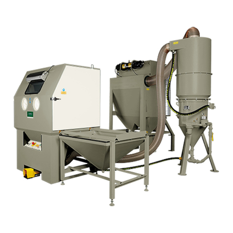
1.4 General Description
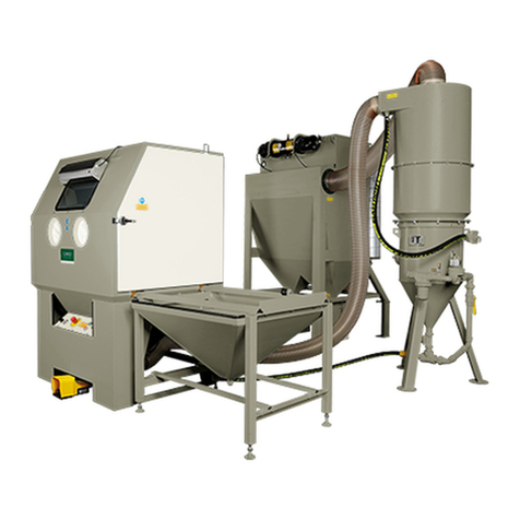
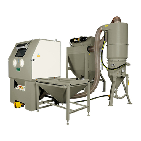
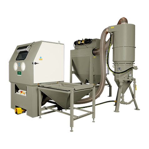
1.4.1 Refer to Figure 1 for the general arrangement of
the cabinet and power module. Components of the
cabinet assembly are shown in Figure 2 and
components of the power module are in Figure 3. The
Pulsar cabinet encloses the blasting environment to
provide efficient blasting while maintaining a clean
surrounding work area. Production rates are influenced
by size of air jet and nozzle, compressor output, working
pressure, type and size of media, and angle and
distance of the nozzle from the blast surface. The Pulsar
IX-P pressure cabinet consists of two major
components.
1. Cabinet Enclosure
2. 900 cfm Power Module
1.4.2 Cabinet enclosure: Approximate work chamber
dimensions at the grate are:
54" wide x 40" deep x 45" high. The extended front
provides approximately 10 inches of additional depth at
the arm port.
