Ancar Sd-150 User manual

SD 150
USER MANUAL


ISO 9001 ISO 13485
109037-AQ-IBE 112630-AQ-IBE
EC Declaration of Conformity (Directive 93/42/EEC)
Manufacturer’s Name
ANTONI CARLES, S.A.
With manufacturing and putting together of medical devices license number 2509-PS granted by
the Health Authorities of Spain.
Name of device: Type or Model:
Dental Unit
GMDNS Code:34991
Sd-150
Device Class according to the intended use and the criteria of Annex IX of the Directive:
Class IIa (rule 11)
Scope of Application: All (including parts and accessories)
Power Supply: 220-240 V ~ / 50-60 Hz
Electric Classification: Type B
This Declaration is based on Certificates issued by DNV:
#78388-2010-CE-IBE-NA according to annex V, DIR 93/42/EEC.
#109037-2012-AQ-IBE-ENAC according to ISO 9001:2008.
#112630-2012-AQ-IBE-NA according to ISO 13485:2003.
Notified Body:
0434 DNV (Det Norske Veritas) – Region Norge As.
We, the undersigned, under our sole responsibility, certify and declare that the medical devices specified
above are in conformity with the essential requirements, which are applicable to them, of RD 1591/09,
transposition to the Spanish law of the directive 93/42/EC as amended by the directive 2007/47/EC. We also
declare that we comply with the design and construction requirements of the following standards:
EN 1640 :2009
Dentistry. Medical devices for dentistry. Equipment.
EN ISO 7494-1:2011
Dentistry. Dental Units. Part 1. General requirements and test methods.
EN ISO 7494-2:2003
Dentistry. Dental Units. Part 2. Water and air supply.
EN 60601-1:2006
+ AC :2010
Medical Electrical Equipment. General requirement for safety.
EN 60601-1-2:2007
+ AC :2010
Medical Electrical Equipment. General requirement for safety.
Electromagnetic Compatibility – Requirements and tests.
EN ISO 14971 :2012
Medical Devices. Application of Risk Management to Medical Devices.
Authorized Signatory Stamp, Date
Josep Álvarez Antoni Carles Bosch November 29, 2013
Regulatory & Safety Officer General Manager
Antoni Carles, S.A.
Volta dels Garrofers, 41-42
Pol. Ind. Els Garrofers
08340-Vilassar de Mar
(Barcelona-SPAIN)
T. (34) 93 754 07 97
F. (34) 93 759 26 04
calidad@ancar-online.com
www.ancar-dental.com
ANTONI CARLES, S.A.
Pol. Ind. “Els Garrofers
C/Volta dels Garrofers, 41-42.
08340 VILASSAR DE MAR
BARCELONA-SPAIN


USER MANUAL DENTAL UNIT - QS4-366-02 / SD 150
1
PAGE
1.- PRECAUTIONS 2
2.- GUARANTEE 2
3.- IDENTIFICATION 3
4.- PRECAUTIONS 3
5.- CLAUSES 4
6.- TECHNICAL FEATURES 5
6.1.- Chair 5
6.2.- Dental Unit 5
7.- DIMENSIONS AND TRANSPORTATION 6
8.- DESCRIPTION 7
8.1.- Circuit box 8
8.2.- Pneumatic pedal 9
8.3.- Instrument tray 10
8.4.- Main keypad 12
8.5.- Water Cabinet 13
8.6.- Cannula support 14
8.7.- Auxiliary keypad 15
8.8.- Headrest 16
8.9.- Optional armrest 16
9.- SAFETY MOVEMENTS 17
10.- CLEANING AND STERILISING 17
11.- TECHNICAL DATA 18
APPENDIX 1. CLEANING AND DISINFECTING OF CATTANI GLASS, CANNULAS
AND BASIN 19
APPENDIX 2. METASYS AMALGAM SEPARATOR 20
APPENDIX 3. CLEANING AND DISINFECTING OTHER PARTS OF THE UNIT 21
APPENDIX 4. DURR VSA300 SUCTION SYSTEM 22
APPENDIX 5. MINILIGHT SYRINGE (LUZZANI)
APPENDIX 6. SAFETY OBSERVATIONS 25
TABLE OF CONTENTS

USER MANUAL
DENTAL UNIT - QS4-366-02 / SD 150
2
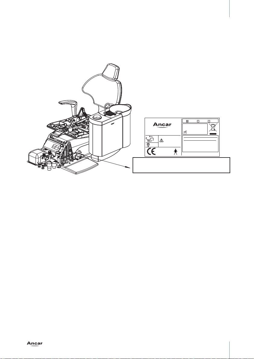
Thank you for purchasing the SD-150 dental unit.
This instruction manual contains information on the dental unit, including its configuration and
maintenance.
0434
This symbol means the unit is certified under Directive 93/42/EEC by
the DNV
Notes
This symbol means CAUTION, PRECAUTION
Before starting-up the unit you must have read and fully understood the user
manual.
Keep this manual in a safe place for future reference, for as long as you use
the equipment.
Follow all safety standards.
It is the user’s responsibility to keep the unit clean, disinfected and in perfect
working order.
1.- PRECAUTIONS
This equipment may only be moved by authorised technicians.
The unit must be installed in an environment with controlled conditions, including temperature
(+10˚C to +40˚C), humidity (30-75 %) and atmospheric pressure (700 a 1060 hPa), free from
dust and condensation and protected from direct sunlight.
The electrical circuit at the premises where the unit is to be installed must satisfy the provisions
in standard IEC 601.1 regarding protection against electric shock for class I equipment.
Antoni Carles, S.A.reserves the right to make any improvements or modifications to the dental
unit without prior warning.
The unit must be used in accordance with the use instructions.
Under Directive 93/42/EEC, the dental unit and dental chair manufactured by Antoni Carles,
S.A.are class IIa equipment. It is absolutely prohibited to install any class IIb or III dental
instrument, e.g. surgical lasers, electronic scalpels, X-rays or electric cauterizers. Only class
I or IIa equipment may be installed, in compliance with the provisions in the aforementioned
Directive and standardised regulations EN60601-1, EN60601-1-2.
2.- GUARANTEE
The device comes with a Certificate of Guarantee. If you do not receive this, ask your dealer
directly. The Certificate of Guarantee must be completed and returned to the manufacturer
(Antoni Carles, S.A.) within 8 days of delivery of the device.
The guarantee is only valid if the device has been used correctly and installed by an authorised
technician.
Moreover, to comply with Health Equipment traceability in accordance with Directive 93/42/
EEC, you must also return the installation form.

USER MANUAL DENTAL UNIT - QS4-366-02 / SD 150
3
3.- IDENTIFICATION
The identification tag, containing technical information required for connection, can be found
close to the base on the side of the chair. It is visible when the outer cover is removed (Fig. 1).
4.- PRECAUTIONS
The unit should be installed in a bright place away from corridors or passageways, and should
have adequate room to accommodate both the patient and the user.
The dental chair should be fixed to the floor to guarantee stability.
Before moving the chair, the operator (Doctor, user) must ensure there is no-one (patient,
guests, children) in the vicinity. Be aware of people around the backrest area and around the
instrument tray.
After using the unit, switch off all instruments as well as the unit itself, which should remain
switched off at the end of each working day.
If the unit is to be out of use for a long period of time, disconnect it from the mains supply and
close the main air and water inlet taps.
Make sure the switch underneath the instrument tray (fig. 6, “H”) is turned off if the equipment
is to be left without staff supervision. This prevents the water pipes from having to sustain a
constant pressure. The air and water inlets must not exceed a pressure of 10.3 Bar, nor should
the pipes be exposed to temperatures exceeding 46˚C, to avoid system faults and damage to
property.
To prolong the working life of the lifting unit components, take care not to overload the chair.
It is advisable not to use mobile telephones in proximity of the working unit.
This equipment is not designed to work in operating theatres.
0434
FABRICANTE/MANUFACTURER/FABRICANT
HERSTELLERS/FABBRICANTE/FABRICANTE
ANTONI CARLES, S.A.
P.I. ELS GARROFERS VILASSAR
08340 (BARCELONA-SPAIN).
CONSULTAR MANUAL
CONSULT MANUAL
CONSULTER MANUEL
LESEN HANDBUCH
CONSULTARE MANUAL
CONSULTAR MANUAL
SD-150 SD-175 SD-60
SN N0211
230V~ / 50 Hz
900W
2006
PRESION/ PRESSURE/PRESSION
DRUCK/ PRESSIONE/ PRESSÂO
AIRE/ AIR/ AIR/ LUFT/ ARIA/ AR:
5,5 Bar / 550 Kpa
AGUA/ WATER/ EAU/ WASSER/
ACQUA/AGUA: 3,5 Bar / 350 Kpa
93/42/CEE, EN60601-1
IPX1
IPX0
SN: N (electrical pneumatic unit)+number
Nxxxx

USER MANUAL
DENTAL UNIT - QS4-366-02 / SD 150
4
ENVIRONMENTAL PROTECTION
All packaging materials are produced in respect for the environment and are fully recyclable:
wooden pallets, cardboard, plastic bags and bubble-wrap. Collecting used materials helps
collection and recycling and reduces waste material.
Antoni Carles, S.A. is obliged to satisfy the objectives set by Community Directives 2002/95/
EC and 2002/96/EC.
This symbol is only applicable for member countries of the European Union.
In order to avoid potential negative consequences for the environment or
human health, this equipment should be disposed of (i) in EU member countries
– in accordance with the WEEE (Waste Electrical and Electronic Equipment)
Directive, and (ii) for all other countries, in accordance with local provisions and
recycling laws.
EMC
The Sd-150 dental unit conforms to the basic requirements of Directive 93/42/EEC concerning
medical devices, and complies with the design and construction requirements contained in
Standard EN60601-1-2 regarding the safety of Electromagnetic Compatibility and Electrical
Medical Equipment, causing no electromagnetic disturbances and complying with immunity
standards.
5.- CLAUSES
Antoni Carles, S.A. will not assume responsibility for damages caused by fire, natural disasters,
third party activities or other accidents caused by operator negligence or misuse, or from using
the equipment under unusual conditions.
Antoni Carles, S.A. will not assume responsibility for damages deriving from the improper use
of equipment, causing a loss of business or loss of earnings.
Antoni Carles, S.A. will not assume responsibility for results of diagnoses made by a doctor
using this equipment.

USER MANUAL DENTAL UNIT - QS4-366-02 / SD 150
5
6.- TECHNICAL FEATURES
6.1.- Chair
Ergonomic design for the patient.
Dental chair with silent, automatic and highly reliable movement.
Microprocessor-controlled movements:
- automatic chair return movement.
- automatic chair-to-spittoon movement.
- 3 programmable chair settings.
High quality, hygienic anatomic upholstery
Safe movement of the base and backrest of the chair, which is raised upwards until locked in place.
Height-adjustable, folding headrest.
Includes Trendelenburg position.
6.2.- Dental Unit
Easy-maintenance finish.
Instrument tray with space to hold 5 instruments and a 14-function control panel. Includes
syringe.
Optional: adjustable electric micromotor. Reversible rotation.
Optional light control panel for instruments with light fitting (micromotor, turbine, ultrasound).
75° rotational water unit, spittoon with automatic cup filler and basin washer system. Optional
fitting of different suction systems and amalgam systems.
Pneumatically braked arm movements with auxiliary instrument tray.
Cannula and circuit boxes located in the front of the chair.
Control panel on instrument tray and cannula support.
The unit is designed to hide all tubes or cables out of sight, except for those on the
instrument tray.
The unit conforms to the basic requirements applied by Directive 93/42/EEC on medical devices,
to the design and construction requirements contained in Standards EN60601-1 and EN60601-
1-2 regarding the safety of Electromagnetic Compatibility and Electrical Medical Equipment,
and to ISO standard 14971, a Risk Management analysis1.

USER MANUAL
DENTAL UNIT - QS4-366-02 / SD 150
6
7.- DIMENSIONS AND TRANSPORTATION
The dental unit is suitably packaged and protected.
The package includes the dental unit secured to a pallet, with a further two cases containing the
water unit and colibri forceps system (Fig. 2).
It is essential that none of the boxes are knocked when in transit, and under no circumstances
must they fall to the floor. Great care should be taken when moving the equipment; we
recommend it be transported by technicians authorised by Antoni Carles, S.A.
Before assembling the unit, a technician, along with yourself and the authorised member of staff
on-site should determine its best location with regard to comfort and ergonomics.
Should you have to move a pre-assembled unit, fit the chair first with the seat
at its lowest position and the back raised, making sure the water unit and
instrument tray are fully retracted over the chair at all times, keeping the unit as
solid as possible.
Once in position, remember to secure the chair to the floor.
2990
MIN: 1130 / MAX: 1540
MAX: 840
MIN:430
950
600
Fig. 2 Dimensions

USER MANUAL DENTAL UNIT - QS4-366-02 / SD 150
7
8.- SD150 DENTAL UNIT DESCRIPTION (Fig. 3)
Fig. 4 Circuit box Page 8
Fig. 5 Pneumatic pedal Page 9
Fig. 6 Instrument tray Page 11
Fig. 7 Main control panel Page 12
Fig. 8 Water unit Page 13
Fig. 9 Cannula support Page 14
Fig. 10 Auxiliary control panel Page 15
Fig. 11 Headrest Page 16
Fig. 12 Armrest Page 16
Fig. 4
Fig. 5
Fig. 6
Fig. 7
Fig. 8
Fig. 10
Fig. 9
Fig. 11
Fig. 12
Fig. 3

USER MANUAL
DENTAL UNIT - QS4-366-02 / SD 150
8
8.1.- Circuit box
The circuit box contains all points for connecting the dental unit to the clinic’s power supply,
as well as controls for adjusting the air and water supply. Regulator directional movement
conforms to Standard UNE 20128.
As indicated in the diagram, the front part of the chair base contains: (Fig. 4)
A. General power switch. Up, on; down, off. Pilot light.
B. General mains fuse, rating T6.3A/250V, type 5x20mm. Fuses should be replaced by an
authorised technician.
C. General compressed air switch. The compressor should be correctly installed to avoid the
build-up of humidity in the air circuit.
D. General water switch. Inlet water must be well purified.
E. Air inlet pressure control. Fitted with a solid particle filter. Check around once per month.
Clean using pressurised water.
F. Water inlet pressure control. Fitted with a solid particle filter. Check around once per
month. Clean using pressurised water.
G. Movement panel connection cover.
H. Connection panel and transformer cover.
Note: when activating the general power switch (“A”), the connection panel will
perform a function test producing an audible beeping sound. If you do not hear
this sound, switch off the unit and contact your technical service provider.
G
H
B
A
+-
EF
DC
Fig. 4

USER MANUAL DENTAL UNIT - QS4-366-02 / SD 150
9
8.2.- Pneumatic pedal:
INSTALLATION AND USE
Pedal for adjusting the optional instruments on the instrument tray: Micromotor, turbine.
Ultrasound on/off switch.
Control the electric micromotor rotation speed, turbine power and pneumatic micromotor by
activating the trigger (B); select air only or air and water, using lever-operated spray function
(A). The pedal-controlled electric micromotor has a speed control indicator, as it allows very
sensitive and progressive movement.
Lever-operated chip blower function (A) when the lever (B) is in the return position.
It does not control cannula support instruments; only those on the instrument tray.
Optional instrument cleaning turbines and micromotors, removing every last
drop of water with an automatic air blower.
Safe movement of all optional instrument tray items: by adjusting the control
lever the chair is locked in place, or it can be secured in any position.
PEDAL FUNCTIONS (Fig. 5)
A. Chip blower control button/lever. Short-burst air blower.
B. Control trigger to activate and adjust the selected instrument while still on the tray.
Pressing the trigger (B): air only, no water.
Pressing the trigger (B) and lever (A): water and air, spray function.
C. Backrest return movement.
D. Manual chair recline movement.
E. Backrest recline movement.
F. Manual chair return movement.
Safety:
To block any button-activated memory, press the control pedal.
When activating the control pedal, all chair movements are blocked.
This pedal can accept as an option the setting to zero automatically. By default,
it is not incorporated.
A
B
FC
E
D
Fig. 5

USER MANUAL
DENTAL UNIT - QS4-366-02 / SD 150
10
8.3.- Instrument tray
The instrument tray (Fig. 6), ergonomically designed to facilitate the work of the user, is also
fitted with an auxiliary instrument tray (A), a slight inclination of the main keypad (B) to provide
easy viewing, and a comfortable chair positioning handle (C). Use the button located on the
front (D) to release the pneumatic brake and to adjust the height position.
The instrument layout (E) has up to five (1,2,3,4,5) positions which can be pre-configured upon
request.
Any later modifications must be carried out by an authorised technician.
The turbine and both pneumatic and electric micromotors can be situated in 4 work positions.
Once their positions are set, the turbine and pneumatic micromotor are interchangeable.
- Silicon instrument support (E), protects instruments from knocks. Can be sterilised and
easily removed for autoclave sterilisation.
- Auxiliary instrument tray installation.
- The smooth, non-porous, rounded-edge tray allows easy access for rapid cleaning and
disinfecting.
- Arm levelling (authorised technician only)
- Arm brake adjustment (authorised technician only)
- Overhead poles protect the instrument if dropped.
- Turbine lamp with pedal-free operation.
- Instrument tray rotation: 125°. 30cm vertical movement.
LOWER PART OF TRAY:
water controllers are located alongside each optional instrument (installed upon request).
E (1, 2, 3, 4)Water controllers are aligned with each optional instrument, installed upon request
(micromotor, light micromotor, turbine, light turbine or ultrasound, respectively).
F Ultrasound power setting.
G Micromotor directional selector.
Should the turbine or micromotor spray function not work, or if there is no water
in the ultrasound, check that these regulators are fully opened by turning them
anticlockwise.
H General air and water switch
This switch must be turned off if the unit is left unsupervised. Deactivating
this switch prevents water pipes from being subjected to constant pressure
through the intake.
J Electric micromotor work mode selector: normal or reduced mode. This allows the user to
work at low speeds within the range of approx. 0 to 3,000 rpm.
K Removable tank for the micromotor and turbine lubrication oil return filter. Check
periodically.

USER MANUAL DENTAL UNIT - QS4-366-02 / SD 150
11
The tray is attached to the unit by means of a pantographic arm, with a pneumatic brake for
comfortable, effortless front positioning (handle side).
F G HE4 E3 E2 E1
K
J
A
B
C
D
E
1
2
3
4
5
E1
E2
E3
E4
Fig. 6

USER MANUALDENTAL UNIT - QS4-366-02 / SD 150
12
8.4.- Main keypad: (Fig. 7)
1. Dental light switch (ON/OFF)
2. Water cup and spittoon taps. Timed, 2-12 seconds. Spittoon and cup taps can be set-up to
work simultaneously or independently.
3. Spittoon water. Timed, max. 3 min. Can be switched off using the same button.
4. Auxiliary switch activation (non-powered contact).
Can be configured as a switch or button.
5. Yellow LED indicating electric micromotor directional change.
6. Press continuously: Manual backrest return:
Press once: Automatic movement to memory #2 position.
7. Press continuously: Manual backrest return.
Press once: Automatic movement to memory #3 position
8. Press continuously: Raise chair manually.
Press once: Automatic movement to memory #1 position
9. Press continuously: Lower chair manually.
Press once: Automatic reset movement.
10. Chair movement positional memory storage button (settings 1, 2 and 3). First press reset.
Set the chair to the desired position using the manual function keys. Hold “Enter” key
(“10”) and press any of the three positions (1, 2 or 3); wait for the “beep” to confirm setting.
Release “Enter” key (“10”).
11. Spittoon return position. Pressing once moves the backrest up to the spittoon.
Pressing it a second time returns the backrest to the original position.
1
2
4
3
6
7
5
8
9
10
11
Fig. 7

USER MANUAL DENTAL UNIT - QS4-366-02 / SD 150
13
8.5.- Water Cabinet
As seen in Fig. 8, the water unit has a rotation of 75° approx. towards the arm support (H),
facilitating the ergonomics of daily use. The column arm (G) supports the dental light and
instrument tray and has a rotation of 120°. The upper part holds the spittoon, made from
porcelain to offer high standards of hygiene. To avoid splashes and the passing of solids, it is
fitted with attachments (F) and (E) located in the drain of the spittoon.
It comes with two stopcocks to cut off the cup water (A) and spittoon water (B). Fitted with
spouts for cup water (P) and basin water ( Q).
The surgical air suction (D) contains a changeable (C) filter, which allows the use of foamless
tablets. The suction of a glass of clean water is recommended after each use, cleaning the filter
at the end of each day. Always clean using manufacturer-recommended products.
The cannula support (R) has an auxiliary keypad (J), medium and large capacity surgical
suction (K) and, as optional instruments, a 3F syringe, a Polymerized Lamp and an Intraoral
Camera (positions Land M).
The cannula support safety (N) connected in sequence with the pedal, blocks any automatic
or manual movement following any slight tilt (S) of the support arm. This safety is particularly
useful following any inadvertent collisions with furniture, stools, etc.
Upon request, the water unit can be supplied with gravity-drained or continuous suction
systems, and with an amalgam separator option for wet- or dry-ring systems. See appendices
to this manual for specific instructions for each manufacturer.
75º
120º
A
NS
G
Q
P
H
F
R
L
M
K
J
C
D
B
E
Fig. 8

USER MANUAL
DENTAL UNIT - QS4-366-02 / SD 150
14
8.6.- Cannula support (surgical suction, instruments, keypad)
The tube support is mounted on an arm with a large capacity of movement to find the desired
position (Fig. 9).
The surgical suction motor is activated by lifting any of the cannulas. Cannulas (A) and cannula-
holders (B) can be sterilised and are autoclave-safe. If not fitted with a continuous suction
system, the separator system should be left for a short emptying period.
SURGICAL SUCTION
Depending on the type of amalgam separator installed (Cattani, Metasys, Dürr), all manufacturers
recommend their own products and methods for disinfecting cannulas, attached to this manual.
The cannula and cannula-holder sterilisation process is the same for all systems.
Both cannula holders and tubes are safe for autoclave sterilisation. It is recommended to use
foamless disinfecting tablets, which can be left to work overnight. Furthermore, the outer tubes and
tongues should be lubricated every 15 days with Lubri-Jet products, drying off any excess water.
3F SYRINGE (Optional)
The second instrument on the cannula support is the 3F syringe, with 3 functions: air, water and
spray. This instrument works independently from the control pedal.
For more information, see the corresponding appendix.
A
B
135ºC
Fig. 9

USER MANUAL DENTAL UNIT - QS4-366-02 / SD 150
15
8.7.- Auxiliary keypad.
The auxiliary keypad (or assistant’s keypad) is located on the cannula support (Fig. 10).
F. Cup tap and spittoon tap. Timed, 2s-12s.
Spittoon and cup taps can be set-up to work simultaneously or independently.
G. Spittoon tap. Timed, 10s-180s. Can be turned off using the same button.
H. Spittoon return position. Pressing this once returns the backrest to the spittoon position.
Pressing it twice will return the backrest to the original position.
J. Pressed continuously: Raise chair manually.
Pressed once: Automatic movement -> Free memory position 1.
K. Pressed continuously: Manually lower backrest.
Pressed once: Automatic movement -> Free memory position 3.
L. Pressed continuously: Lower chair manually.
Pressed once: Automatic movement: -> Reset.
M. Pressed continuously: Manually raise backrest.
Pressed once: Automatic movement -> Free memory position 2.
FGH
J MK L
F
J
H
K
M
G
L
Fig. 10

USER MANUAL
DENTAL UNIT - QS4-366-02 / SD 150
16
8.8.- Headrest
Thanks to its articulated movement, this head support allows the patient’s head to be positioned
easily and ideally, according to the treatment required. It can be easily adjusted lengthways, as
shown in Fig. 11.
OPERATION
- The lengthways adjustment is easily connected. The piece is gripped firmly with the position
held internally.
- Turn piece “A” to achieve the desired inclination. Once the headrest is set in the optimal
position, lock the mechanism by turning lever “A” in a clockwise direction.
The head support upholstery can be replaced simply by removing it from the base, allowing
comfortable maintenance.
8.9.- Optional armrest
To rotate the armrest, it must be pulled upwards (kept in its housing) until the rotation mechanism
is released, allowing it to be turned until reaching the track limit where it stops. To return the
armrest to its initial position, simply lift it and turn it inside until it locks automatically (Fig. 12).
A
Fig. 11
Fig. 12
Other manuals for Sd-150
1
This manual suits for next models
1
Table of contents
Other Ancar Dental Equipment manuals