Anchor Aloha User manual
Please read all assembly / installation instructions before the installation or removal of this product.
Check out our great installation video on our website! AlohaC 920EC5549
Installation Instructions
Aloha Cabana
7701 Highway 41 N
Evansville, IN 47725
Phone: 812-867-2421
Fax: 812-867-1429
1-800-544-4445
email: [email protected]
www.anchorinc.com

2
Introduction
The installer/owner must read the assembly instructions completely prior to any installation. Particular attention
must be given to anchoring! See Caution Statement on back page of this manual.
Work from step to step.
Before erecting any tents or membrane structures, first obtain permits and approvals as required from the local
building and fire code officials on the jurisdiction of your installation.
PLEASE PAY SPECIAL ATTENTION TO SAFETY WARNINGS AND CAUTIONS FOR PREVENTION OF ACCIDENTS.
Regarding the contents of this document:
The illustrations and photos are made to show clearly the construction and dismantling procedures and also for
identification of the components. Not all illustrations/photos correspond to the actual dimensions and size. Expla-
nations and/or notes have been added to these illustrations/photos.
If you have questions, please call your sales representative at the phone number listed on the front of this manual.
Safety Notes
Warning: The Aloha Cabana is intended for concrete Install only. Installer is solely re-
sponsible for evaluating the quality of the concrete and its suitability for this structure.
Concrete installation surface must be level.
Manpower Required:
Four installers should be able to assemble any size frame with fabric in two hours.
Caution:
Please read through this assembly manual completely before beginning your installation. Be sure the proper
equipment and safety precautions are in place. We hope that you enjoy the design features of the Aloha Cabana.
1. Be aware to avoid contact of frame sections with any overhead power lines near the site.
2. Consult your local utility locator service or the National Utility Locating Contractors Association (NULCA) prior
to installation in order to avoid all underground power lines and gas lines or other utility easements.
3. Keep site clear of debris to avoid tripping, especially while carrying frame parts or bundle of fabric.
4. When moving frame sections by hand, use proper lifting techniques to protect the back, and avoid pinching
fingers while making hardware connections.
5. Do not drag bundle of fabric on concrete, asphalt, or ground as this can cause damage to the fabric from abra-
sion through the bag.
6. The installation method described here requires coordination of tasks between workers. A safe installation is
dependent on that coordination. Work cooperatively as a team.
7. This tent is manufactured for use as a temporary sun shade structure. Evacuation is recommended if threaten-
ing or windy weather occurs.
Tools Required (not supplied)
5/8” Ratchet or wrench (for Acorn Nuts)
7/32” Allen wrench (for Bolts)
5/16” Allen wrench (for Upright Mechanism)
Tape Measure
Chalk or spray paint for marking layout
3
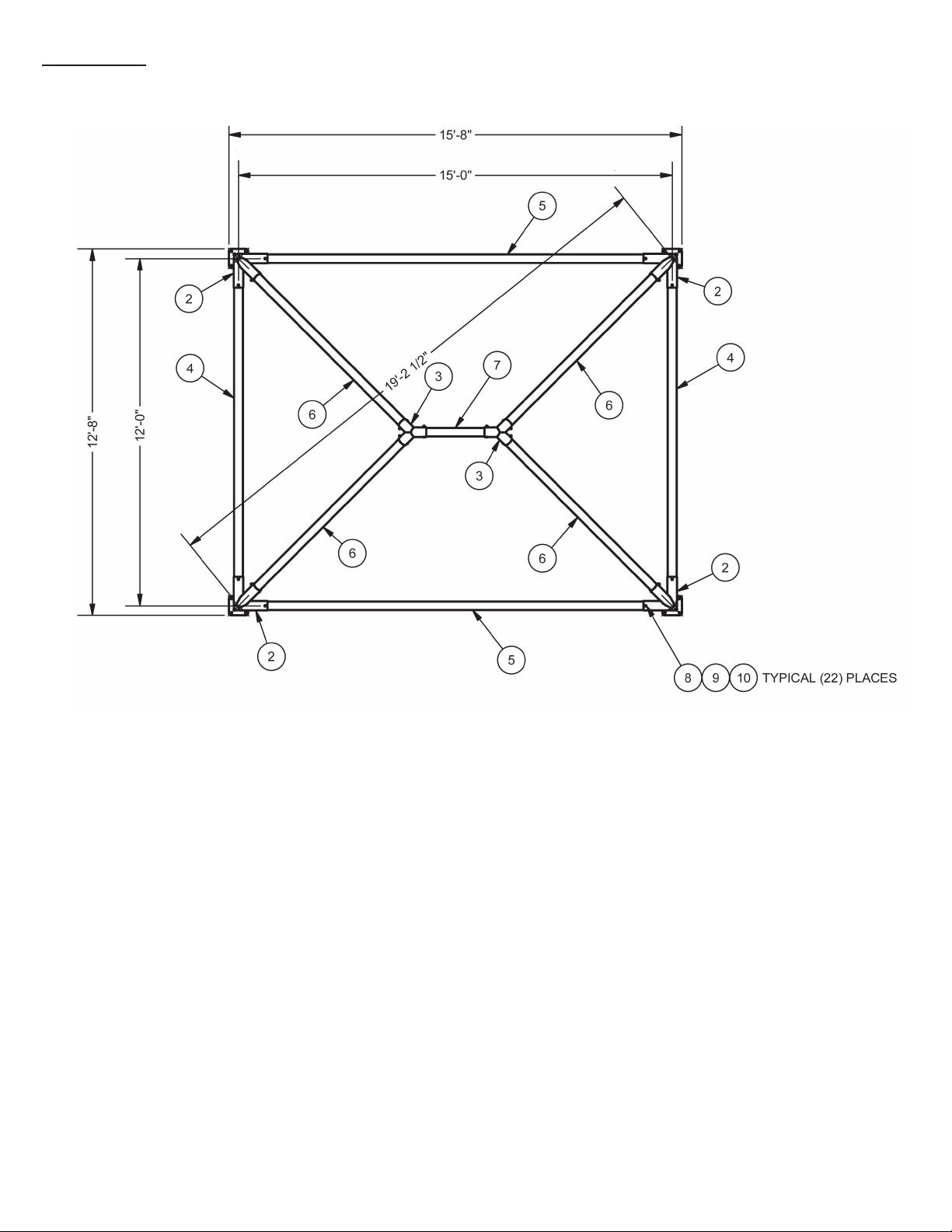
Layout
o/o of base plates
o/o of base plates
center/center of base plates
center/center of base plates
Using chalk or spray paint, mark center point of each base plate.
4
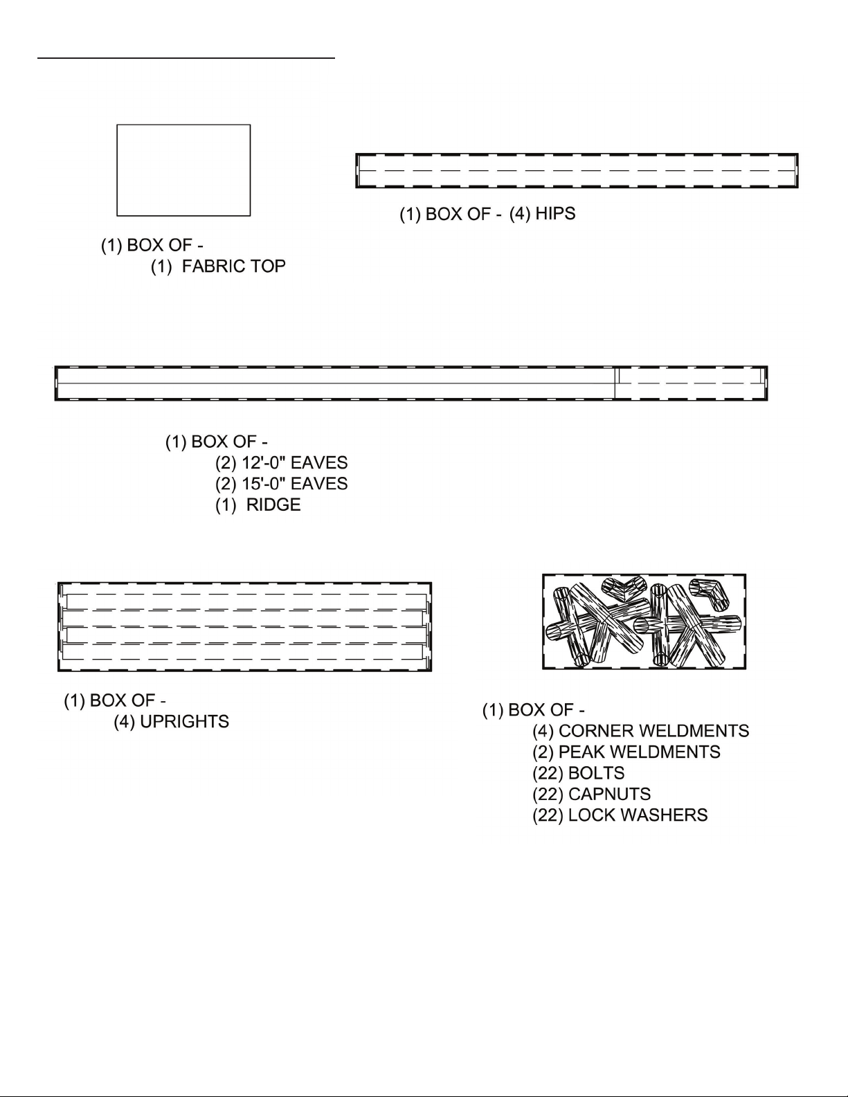
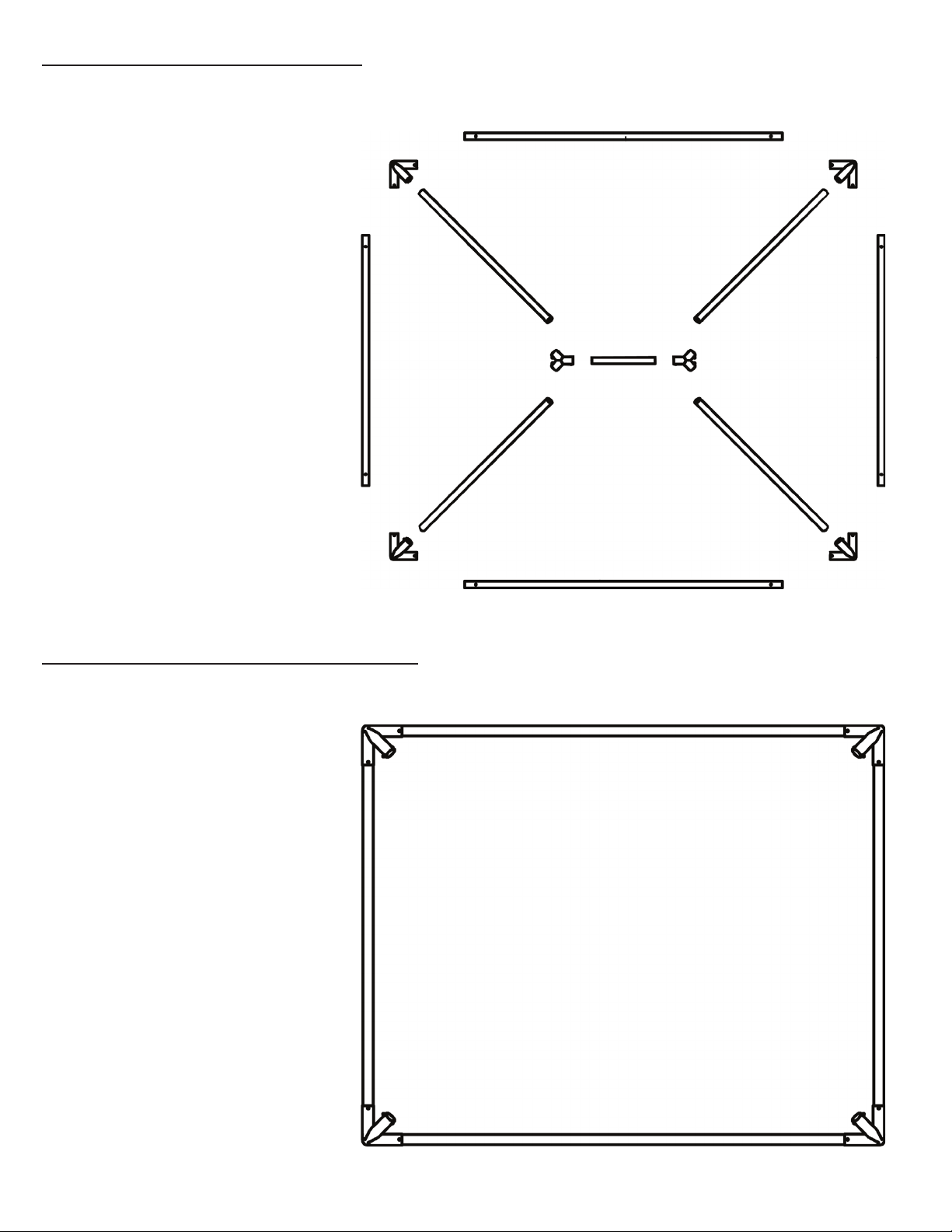
Step 1 - Layout Boxes
5
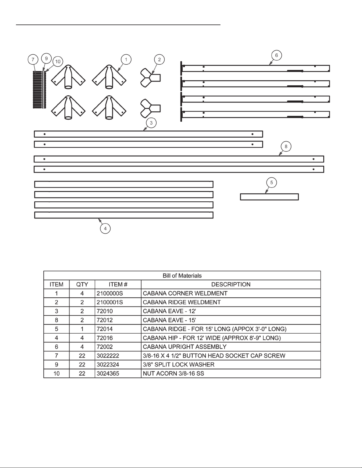
Step 2 - Layout Parts on Drop Cloth
6
Step 3 - Layout Parts
Step 4 - Assemble Eaves
Identify and layout all components for assembly.
• Insert eave tubes into corner weldments
with the channel toward the ground.
• Align holes.
• Insert bolt from top.
• Fasten using lock washer and acorn
nut.
• Hand tighten.
7
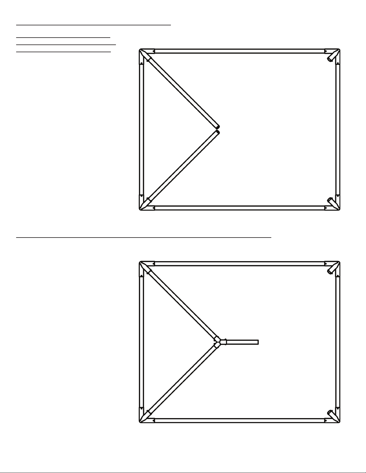
Step 5 - Assemble (2) Hips
Step 6 - Assemble Ridge Weldment & Ridge
• Insert hip tubes with channel toward
ground into corner weldments .
• Align holes.
• Insert bolt.
• Fasten using lock washer and acorn
nut.
• Hand tighten.
• Insert ridge weldment onto hip tubes.
• Align holes.
• Insert bolts.
• Fasten using lock washer and acorn
nut.
• Hand tighten
• Insert ridge tube with channel toward
ground into ridge weldment.
• Align holes.
• Insert bolt.
• Fasten using lock washer and acorn
nut.
• Hand tighten.
Important Note: The end of the hip
tubes with the greater distance to the
hole goes into the corner weldment.

8
Step 7 - Assemble Ridge Weldment & 1 Hip
Step 8 - Assemble Remaining Hip
• Insert hip tube with channel toward
ground into corner weldment.
• Do not try to align holes at this point.
• Insert top of hip tube into ridge weld-
ment.
• Align holes.
• Insert bolt.
• Fasten using lock washer and acorn
nut.
• Hand tighten.
• Align holes at bottom of hip to corner
weldment.
• Insert bolt.
• Fasten using lock washer and acorn
nut.
• Hand tighten.
9
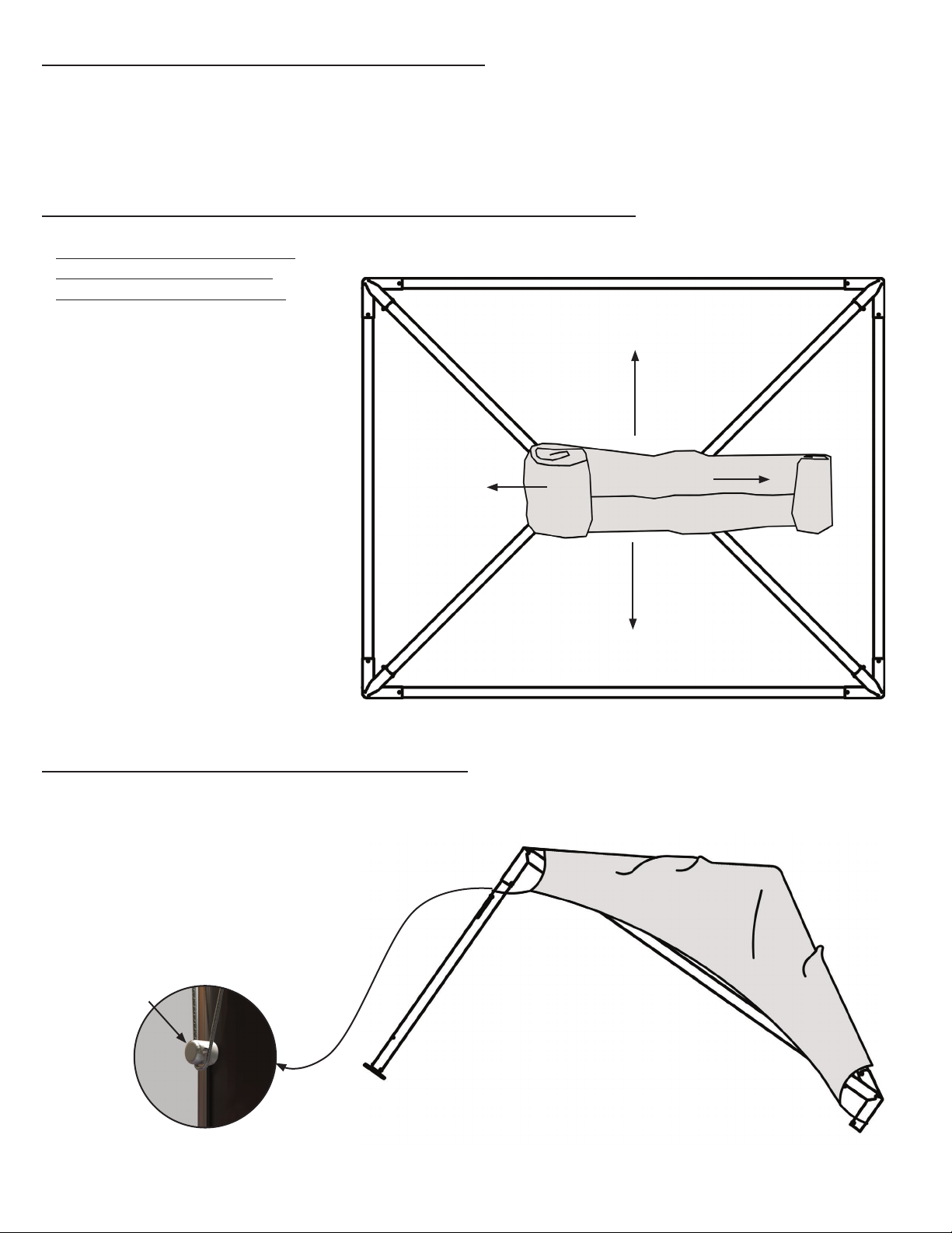
Step 10 - Place Fabric on Top of Frame
Step 11 - Raise one 15’ Side
Step 9 - Tighten Connections
• Place tied fabric bundle on top of
ridge of frame.
• Untie.
• Unroll bundle in the order and direc-
tion of the arrows shown.
• Unroll fabric until it is setting loosely
on frame in the proper position.
• Now that frame is assembled, go back to each
connection and using a 5/8” ratchet and 7/32”
allen wrench, tighten all connections.
• Raise one 15’ side using a ladder.
• While frame is raised, insert uprights with cable
bolt to outside into the corner weldments.
• Align holes.
• Insert bolt.
• Fasten using lock washer and acorn nut.
• Hand tighten.
Cable bolt
1
2
3
4
Warning: Do not attempt
to install fabric if wind
speed is 10mph or more!

10
Step 12 - Raise Opposite 15’ Side
Step 13 - Final Tightening of Upright Connections
• Beginning at one upright, tighten connection to
corner weldment using a 5/8” ratchet and 7/32”
allen wrench.
• Proceed to diagonal upright, do the same thing.
• Tighten connections of remaining uprights.
• Raise the remaining 15’ side using a ladder.
• While frame is raised, insert uprights into the
corner weldments with cable bolt to outside.
• Align holes.
• Insert bolt.
• Fasten using lock washer and acorn nut.
• Hand tighten.
Warning: Top must
be secured to frame before
continuing installation. Pull
corner cables of top down
over the slotted cable bolts on
uprights. This is to prevent top
from being picked up by wind.
Warning: Do not attempt
to install fabric if wind speed is
10mph or more!
11
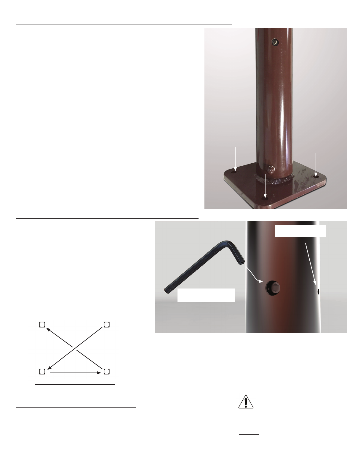
Step 13 - Mount Frame to Foundation
• Move frame into position, center baseplates over original
layout markings.
• Check to be certain that frame is square, vertical and level.
Frame must be secured to foundation. (4) 5/8” Diameter holes
are provided in each base plate for this purpose.
Step 15 - Tension Top to Frame
Step 16 - Take Down
• Check to make sure that all corner cables of
top are pulled down over the slotted cable bolts
on the uprights.
• Using the 5/16” allen wrench, tension one
corner cable down until top is 2” from corner of
frame. (This is accomplished by inserting the
allen wrench into the larger hole near the bot-
tom of the upright and turning)
• Proceed to the diagonal corner and repeat this
process (See Top Tensioning Order Diagram).
• Continue tightening the top in this same order
until top is balanced all the way around the
frame and fits snugly.
• Release top by inserting the smaller allen wrench
• Hit allen wrench firmly with palm of hand. - Warning! Release will be loud!
5/16” allen wrench for
tensioning top down.
7/32” allen wrench
for releasing top.
1
23
4
Top Tensioning Order Diagram
Warning: Do not at-
tempt to remove fabric if
wind speed is 10mph or
more!

12
Base Plate Cover
Installation
(Optional purchase)
• Slide the two parts of the cover together
over the base plate. (Figure 1)
• Starting at the side of the cover where the
two parts come together, insert screws and
loosely fasten cover to base plate. (Figure
2)
• Continue all around the base plate, loosely
fastening cover to base plate while watch-
ing to be sure cover fits evenly around
upright for the best look. (Figure 3)
• When you are satisfied with the placement
of the covers, tighten screws. (Figure 4)
Figure 1
Figure 2
Figure 3 Figure 4

13
Retractable Drapes
(Optional purchase)
• Layout drapes to determine where
each drape should hang. See tag
at bottom corner to see size and
right or left.
• Using a ladder, feed tabs at top
of drapes into channel at bottom
of eave tube. Start with angled
corner edges.
• Feed all tabs into channel.
See slotted opening at center of
channel at bottom of eave tubes.
Inside View
Eave tube
15L
15L
15R
15R
15’ SIDE
12’ SIDE
12L 12R
12R
12L
Drapes Shown From Outside View

14
Fasten drapes together at corners with
velcro and menax fasteners on outside
of corner uprights.
To keep drapes in open position,
gather drapes together and wrap belt
around drapes twice. Fasten belt with
menax fastener.
Note: There are small tabs at top and
bottom of drapes at corners for tieing
together with zip ties. Zip ties not
included.
To close drapes, draw together
and fasten with velcro and
menax fasteners.
Inside View
Outside View

$QFKRUSURGXFWVDUHRIVXSHULRUGHVLJQDQGRSHUDWHEHVWZLWKLQWKHSDUDPHWHUVRIWKHVHLQVWUXFWLRQV,WLVLPSHUDWLYH
WKDWWKHLQVWUXFWLRQVEHFDUHIXOO\UHDGDQG&203/(7(/< )2//2:('3OHDVHUHDGLQVWDOODWLRQLQVWUXFWLRQVEHIRUHWKH
LQVWDOODWLRQRUUHPRYDORIWKLVSURGXFW,QVWDOODWLRQLQVWUXFWLRQVDUHDYDLODEOHRQOLQHDWZZZDQFKRULQFFRP RUE\FDOOLQJ
WARNING:
)RUHDFKLQVWDOODWLRQWKHLQVWDOOHULVVROHO\UHVSRQVLEOHIRUHYDOXDWLQJWKHVLWHDQGWKHSURSHUVHFXULQJPHWKRG
GHWHUPLQHG6RPHVRLOVUHTXLUHGLႇHUHQWVWDNLQJRUVHFXULQJWKDQWKDWSURYLGHGZLWKWKHWHQW'XHWRWKLVYDULHW\
RIVRLOFRQGLWLRQVWKHVHDUHWKHPDQXIDFWXUHU¶VVXJJHVWHGVHTXHQFHRILQVWDOODWLRQSURFHGXUHV$QFKRU¶V
UHVSRQVLELOLW\LVOLPLWHGWRWKHPDQXIDFWXUHRIWKHWHQWSDUWVDQGPDWHULDOV:HDUHQRWUHVSRQVLEOHIRUPHWKRGVWKDW
LQVWDOOHUVPD\FKRRVHWRHUHFWDQGVHFXUHWKHWHQWWRWKHJURXQG
7KHPRXQWLQJPHWKRGVXJJHVWHGLQWKHLQVWDOODWLRQLQVWUXFWLRQVGRHVQRWQHFHVVDULO\PHHWDOORUDQ\UHOHYDQWFRGHV
RQWKHVLWHRIWKHLQVWDOODWLRQ7KHPHWKRGVXJJHVWHGZLOOLQPDQ\FDVHVNHHSWKHVWUXFWXUHHUHFWHGKRZHYHU
GXHWRYDULRXVVRLOFRQGLWLRQVWKLVPHWKRGPD\EHLQVXႈFLHQWWRNHHSWKHVWUXFWXUHVHFXUHLQKLJKZLQGV,WLV
WKHLQVWDOOHU¶VUHVSRQVLELOLW\QRWWKHPDQXIDFWXUHUWRGHWHUPLQHWKHDSSURSULDWHPHWKRGRIVHFXULQJWKHVWUXFWXUH
WRPHHWWKHQHFHVVDU\ZLQGORDGVRQWKHVLWH5HJDUGOHVVRIWKHPRXQWLQJPHWKRGZHVXJJHVWZHPDNHQR
UHSUHVHQWDWLRQRUZDUUDQW\DVWRZKHWKHUWKHPRXQWLQJPHWKRGVXJJHVWHGZLOOPHHWWKHORFDOFRGH$QFKRUGRHV
QRWQRUFDQLWPDNHDQ\VXJJHVWLRQVUHSUHVHQWDWLRQRUZDUUDQWLHVDERXWWKHDGHTXDWHPRXQWLQJUHTXLUHGDWHDFK
VSHFL¿FLQVWDOODWLRQVLWH
,QDVPXFKDVWKHZHDWKHULVXQSUHGLFWDEOHJRRGMXGJPHQWDQGFRPPRQVHQVHPXVWEHLQFRUSRUDWHGZLWKLQ
LQVWDOODWLRQJXLGHOLQHV,WLVWKHUHVSRQVLELOLW\RIWKHLQVWDOOHUPDLQWDLQHUWRGHWHUPLQHWKHVHYHULW\RIWKHZHDWKHU
SURSHUWLPHDQGPHWKRGRILQVWDOODWLRQDQGRUHUHFWLRQDQGGLVDVVHPEO\1RWH:HUHFRPPHQGWKDWVQRZDQG
LFHEHUHPRYHGIURPWKHWHQWVXUIDFHDVVRRQDVSRVVLEOHEHFDXVHDFFXPXODWLRQZLOOGDPDJHWKHWHQW
RUIDEULFVWUXFWXUH3OHDVHFRQVXOWZLWKRXU(QJLQHHULQJ'HSDUWPHQWDERXWWKHPD[LPXPORDGVIRUHDFK
SURGXFW
7KLVSURGXFWKDVEHHQPDQXIDFWXUHGIRUXVHDVDWHPSRUDU\VXQVKDGHVWUXFWXUH)RUWKHVDIHW\RIDOORFFXSDQWV
HYDFXDWLRQLVUHFRPPHQGHGLIWKUHDWHQLQJZHDWKHURFFXUVRULIWKHUHLVDQ\GRXEWFRQFHUQLQJWKHVDIHXVHRIWKLV
SURGXFW
3URSHUVDIHW\HTXLSPHQWVKRXOGEHXVHGDWDOOWLPHVWRLQVXUHDVDIHLQVWDOODWLRQDQGWDNHGRZQ:HVXJJHVWD
FDUHIXOHYDOXDWLRQEHPDGHWRGHWHUPLQHVDIHW\HTXLSPHQWQHHGHGVXFKDVKDUGKDWVVWHHOWRHVKRHVVDIHW\
JODVVHVDQGRWKHUDVUHTXLUHG,WLVRXUGHVLUHWKDWDOOLQVWDOODWLRQVDUHVDIH3OHDVHEHDZDUHRIKLGGHQGDQJHUV
ERWKXQGHUJURXQGLHJDVOLQHVZDWHUOLQHVHOHFWULFDOOLQHVHWFDQGDERYHWKHWHQWVXFKDVSRZHUOLQHVDQG
WHOHSKRQHOLQHV
$QFKRUVWDQGVEHKLQGLWVSURGXFWVLQDFFRUGDQFHZLWKLWVVWDQGDUG7HUPVDQG&RQGLWLRQVRIVDOH$FRS\RIRXU
7HUPVDQG&RQGLWLRQVRI6DOHFDQEHREWDLQHGE\FRQWDFWLQJ$QFKRUDWWKHWHOHSKRQHQXPEHUDQGRUDGGUHVVRQ
WKLVGRFXPHQW
3+21(180%(5
āā
)$;180%(5
āā
1R6W
Table of contents


