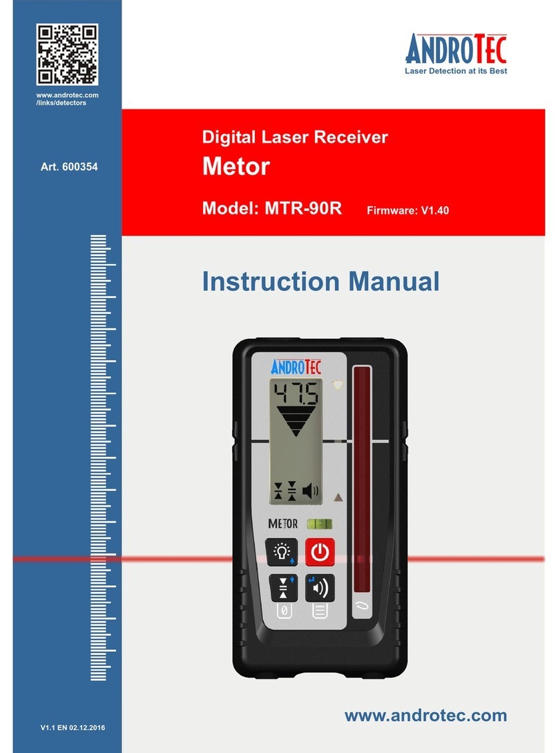
AndroTec Metor MTR-125 User manual

Operator's Manual
Handheld Laser Receiver
MTR-125
MTR-125 RF

Thank you for purchasing AndroTec METOR. Your handheld laser
receiver is a premium quality tool which has been designed and
manufactured to provide years of precise and reliable performance.
IMPORTANT: This manual is an important part of your purchase as
it will familiarize you with the unit and explain the numerous features
that have been designed into it. Please read this manual thoroughly
before use.
Please contact your AndroTec dealer or AndroTec in case you have
questions regarding specific applications or if you require additional
information.
IMPORTANT: Fill out the warranty registration card and return it to
AndroTec GmbH within six weeks after purchase to obtain the full
three year guarantee.
Please record your information below for future reference.
MODEL: ________________________________
SERIAL NUMBER: ________________________________
DATE OF PURCHASE: ________________________________
PURCHASED FROM: ________________________________
________________________________
________________________________
PHONE: ________________________________

V1.2EN 18.02.2010
1
Table of Contents
1General description 2
2Included in delivery 3
3Installing the batteries 3
4Front view 4
5Rear view 5
6Keypad 6
7Secondary key functions 7
8Display 8
9Advanced functions / Memory 12
10 Menu Functions 14
11 Radio Function (MTR-125 RF only) 18
12 Rod Clamp 19
13 Specifications 20
14 Warranty 21
15 Maintenance and Safety 22
16 Disposal 23
17 CE Declaration of Conformity 24

2
1General description
AndroTec METOR is ahandheld laser receiver, designed to receive
and to display reference elevation information from red and infrared
rotational lasers. A large 127mm vertical reception window captures
the laser beam using AndroTec’s patented X²L sensor technology.
Elevation information is output via two liquid crystal displays (LCDs,
one in the front, one in the rear) and three bright LEDs in the front. A
beeper additionally emits adjustable audible signals.
The LCDs indicate elevation information by applying both graphical
symbols (proportinally growing or shrinking arrows plus centrer bar)
and numerals. While the graphics visualizes high, low, or on-grade
the numerals display the distance to on-grade.
Accuracy levels, units of measure, sound levels, and various other
user options are selectable to meet a variety of job requirements.
METOR was specifically designed for use in harsh construction en-
vironments. Strobe rejection technology, overmolded housings, re-
cessed windows, waterproof design and durability are incorporated
into every AndroTec METOR.
A general-purpose clamp is included and serves to mount the de-
tector on various grade rods and staffs. A secondary offset mounting
location provides additional versatility in certain applications. A pa-
tented reversible wedge on the clamp allows sure grip mounting to
round, oval, square, and rectangular rods, as well as various sizes
of wooden staffs.

3
2Included in delivery
The retail pack contains:
AndroTec METOR handheld laser receiver
Rod clamp
Two AA batteries
Operator’s manual
Warranty registration card
Optional available accessories:
Data cable to copy METOR's memory content to a PC
Bubble vial kit for rod clamp
PC radio module for monitoring applications
(MTR-125 RF only)
3Installing the batteries
1. Open the battery door using a coin or similar pry device to release
the battery door tab.
2. Insert two AA batteries noting the plus (+) and minus (-) diagrams
inside the battery housing.
3. Close the battery door. Push down until it "clicks" into the shut
position.

4
4Front view
1 - Keypad: Power, accuracy, me-
mory and volume keys. Refer to
page 6.
2 - LEDs: Easy to see LEDs show
position of METOR relative to the
laser beam. Green for on-grade,
Red for high, and Blue for low.
3 - Beeper:Fast beeps indicates too
high, lower to get to on-grade.
Continuous signal is on-grade. Slow
beeps is too low; raise to get to on-
grade.
4 - Bubble Vial: Helps to keep
METOR level for accurate readings.
5 - Anti-strobe-sensor: Detects
strobe lights and rejects their input
on laser reception.
6 - X²L sensor: Window must be
directed towards laser.
7 - Display: Shows elevation information, receiver settings and
status. Refer to page 8.
8 - On-grade mark (for center on-grade position)

5
5Rear view
9 - Battery door and latch:
Waterproof housing holds two
"AA" batteries.
10 - Marking notch for center on-
grade position. Top of detector is
80mm from marking notch.
11 - Captive screw thread -for
center on-grade position.
12 - Captive screw thread -for
offset on-grade position. Refer to
page 11.
13 - Clamp guides: Dimples align
rod clamp.
14 - ID label with serial number
15 - Display: Refer to page 8.
16 - Rubber over mold: Protects
the receiver from accidental drops.

6
6Keypad
1 - Power key: Press the power key to turn
power on. All LEDs, the LCD and the beeper
will come on momentarily. 'CAL' will be dis-
played and LEDs sequenced as the unit goes
through a self-calibrating procedure for
approximately three seconds.
NOTE: Do not power up the unit in a laser beam or strobe.
Otherwise, the unit will revert to the previous calibration and 'E200'
is displayed.
Press and hold the power key for 2 seconds to turn power off.
2 - Memory key: Refer to page 12.
3 - Volume key: Pressing the switch cycles LOW, MEDIUM, HIGH
and OFF. One beep is emitted at the selected volume when
changed. When sound is OFF, a single beep will signal that a laser
beam has been detected.
4 - Accuracy key: Press once to numerically display current
accuracy setting on the LCD. Press again while the accuracy is
displayed (within one second) to change the current selection.
Subsequent presses will cycle through five accuracy options
(ULTRA FINE, SUPER FINE, FINE, MEDIUM, COARSE). Refer to
page 20 (Specifications).

7
7Secondary key functions
5 - LED-brightness: Pressing the memory
and volume keys simultaneously enables
the selection of LEDs' brightness. Press
together to cycle through OFF, DIM and
BRIGHT. The LEDs will display the current
level of brightness selected as the
switches are pressed. The light bulb
symbol on the LCD will also change to
display the selected setting.
6 - Menu: Pressing the accuracy and volume keys together enters
the menu functions. Refer to page 14.
6a: In Menu mode, the up arrow (accuracy key) scrolls the menu up,
the down arrow (volume key) scrolls the menu down.
6b: In Menu mode, the enter arrow (memory key) enters or selects
the available options.
7 - Hold key (power key): Freezes the last measurement. Refer to
page 12.

8
8Display
1Grade indication arrows
2Radio enabled / in range
3Laser out-of-level / laser low battery
4 LED brightness
5Beeper volume level
6Timer
7Units of measure
8Numeric elevation / Menu text display
9Menu text display
10 Accuracy (Deadband) indicator
11 Offset on-grade clamp location
12 Battery status indicator
1 - Grade indication arrows: Ten individual levels of grade
information for above and below grade. Arrow size increases as
distance away from on-grade increases. Arrow bars can be selected
to represent the selected deadband or can be proportional to the
vertical reception range. Refer to page 15 for details. Horizontal bar
indicates on-grade.
Out-of-beam display: A sequence of arrows indicates if the receiver
has moved beyond the vertical reception range and will indicate in
which direction to move to get back to the laser beam. Refer to page
16.

9
2 - Antenna symbol (MTR-125 RF only): Indicates, that radio is
enabled (radio mode "PC") or in range (radio mode "MT" or
"GL"). Refer to page 18 for further information on radio
functions.
3 - Laser out-of-level and laser low battery warning: Some laser
transmitters can signal warnings by changing the rotation speed
(RPM) of the laser. When enabled, the transmitter outline is
displayed with the appropriate out-of-level or low battery symbol.
If a laser out-of-level is detected, the bubble vial symbol will
blink. Additionally, the beeper will emit an alternating hi-low
tone as a distinct warning, even if the beeper has been turned off.
No elevation information will be displayed.
If a laser low battery warning is detected, the battery symbol
will blink. Elevation information will be displayed normally.
Refer to page 16 for details on enabling these warnings.
4 - LED Brightness: The Symbol indicates if LEDs are OFF, DIM or
BRIGHT. No display indicates LEDs are OFF.
NOTE: Switching the LEDs off extends battery life.
5 - Beeper Volume: indicates if selected beeper volume is LOW,
MEDIUM, LOUD or OFF. No symbol represents OFF.

10
6 - Timer: This Symbol indicates an activated timer function. Refer
to page 12.
7 - Units of measure: Indicates if centimeters (cm), millimeters
(mm), inches (in), or feet (ft) is selected.
8 / 9 - Numeric elevation / Menu text display: When in
the normal operating mode, the four-character graphic
displays numeric elevation. Resolution and the decimal point will be
determined by the units of measure and the accuracy selected.
Refer to page 20 (Specifications) for details.
Dashed lines across the display indicate the numeric
vertical reception range has been exceeded.
The numeric display may also be turned off. Refer to page 15 for
details.
When in the MENU mode, the menu function text
abbreviations will be displayed. Refer to page 14 for
details.
10 - Accuracy indicator: Indicates five levels of accuracy selec-
tions: ULTRA FINE, SUPER FINE, FINE, MEDIUM and COARSE.
Refer to page 20 (Specifications) for the specific values for each
accuracy selected. No center bar is displayed for calibration mode.
Refer to page 13. This mode is intended only for calibration of
rotational lasers and not for normal operation.

11
METOR allows two different mounting positions for the rod clamp
which are detected automatically. A corresponding symbol is
displayed.
NOTE: Other clamps than the original METOR clamp can not be
detected by METOR and can lead to measuring errors in offset
position.
11 - Offset on-grade clamp position: This clamp position
yields a larger range above on-grade. This is useful in
applications where going below grade is not required, i.e. driving
stakes down to grade.
This symbol is blinking if a user defined on-grade position is set
(refer to page 13). Refer to page 19 for further information about the
rod clamp.
12 - Battery status: Indicates four levels of battery status. Battery
life is approx. 60 hours with fresh batteries.

12
9Advanced functions / Memory
Capture / Timer: The capture function is used to obtain a
single reading and keep it displayed. This is useful when the
unit may not be visible while grade information needs to be
obtained.
When METOR is in the laser beam and power is on, momentarily
press the power/capture switch. The current elevation reading will
be captured. A flashing display will confirm the reading has been
captured. Press any key to return to normal operation.
When out of the laser beam and power is on, momentarily press the
power/capture key. A short intermittent beep and 'WAIT' displayed
on the LCD confirms the timer mode. The beeper will be switched to
low volume if it was turned off. Move the receiver in-beam. After five
seconds a rapid chirp from the beeper and a blinking display
confirms successful capture. Press any key to return to normal
operation.
Memory: Memory key allows storing and displaying stored
measurements.
When the memory key is pressed while a measurement is
displayed (while in beam or with a captured measurement), the slot
number will blink below the measurement value. The slot number
can be scrolled with the arrow keys (accuracy and volume keys).
The measurement is stored to the selected slot by pressing the
memory key a second time. CAUTION: Any existing measurement
in this slot will be overwritten. Power key cancels storing procedure.
When the memory key is pressed while no measurement is
displayed, the display shows the contents of the memory (stored
measurement and slot number). Pressing the memory key for two
seconds deletes the current slot ('DEL' is displayed).
When the memory key is pressed for two seconds outside memory
display, METOR enters the memory menu (refer to page 17).

13
User defined on-grade level: Any arbitrary level within
30mm above or below the marking notch can be used as
on-grade level. The user defined on-grade level is set by
pressing the accuracy key for two seconds while in beam or while a
captured height level is displayed. The actual height will be used as
on-grade level and the offset on-grade symbol blinks.
When the accuracy key is pressed for two seconds while out of
beam, the on-grade level is reset to default.
Calibration Mode: Pressing the power and accuracy
keys together when the unit is off enables entry into a
laser calibration accuracy mode. This accuracy is
designed to be used when calibrating a laser. It is not
recommended for field use.
Calibration mode will be confirmed on the LCD by the accuracy
indicators without the on-grade bar.
Press the accuracy key or cycle power to exit the calibration mode.

14
10 Menu Functions
NOTE: The menu functions can be used to edit various options. For
most applications the factory defaults are the best choice. We
recommend to change settings only in special applications.
The menu screen is accessed by pressing the accuracy
and volume keys together for approximately two seconds.
'MENU' will appear in the numeric display area. After two
seconds the first line displays the menu function. The
second line is the current setting for that function. The
remainder of the LCD will be clear. No elevation
information will be displayed while in the menu screens.
Menu items are selected by scrolling up or down with the accuracy
and the volume keys, indicated by the small blue arrows ().
Menu items are entered by pressing the memory key (blue
enter symbol ). Once entered, the current setting will blink.
To change the current setting, use the blue arrows to scroll
through the options for that function. Press the blue enter arrow
(memory key) to confirm the current selection.
To exit the menu scroll to 'EXIT' and press enter. Alternatively, the
power key can be used to back up one step or to exit the menu.
NOTE: All menu settings will be retained when METOR is turned off.
RDIO -Radio (MODE / PAIR / TEST), MTR-125 RF only:
The symbol "" indicates a sub menu. Press the Memory key to
enter ().
MODE (OF / MT /GL / PC): Selects radio mode
PAIR: Starts pairing in the selected radio mode
TEST: Test function (Service use only)
See page 18 for a detailed description of radio functions.

15
SENS -Sensitivity (LO / MD / HI): Selects reception sensitivity to
laser and other light sources.
LO (Low) is used if outside sources are disturbing elevation
readings.
MD (Medium) is used for most applications and is default setting.
HI (High) can be used when working with a weak laser beam or if
the beam needs to be picked at very long distances. NOTE: Refer
to the laser's specifications for accuracy and distance information.
AVG -Numeric and Arrow Averaging (LO / MD / HI): Averages
laser beam strikes to improve arrow display performance at long
distances. Averaging is also affected by laser RPM and accuracy
setting.
LO (Low) uses minimum averaging to display laser strikes.
MD (Medium) is default setting and used for most applications.
HI (High) can be used in windy conditions, when the laser beam
may be unstable, or when working at long distances. NOTE:
Refer to the laser's specifications for accuracy and distance infor-
mation.
D.R.O. -Digital Read Out (OF / DB / HI): Turns the numeric display
ON (DB) or OFF (OF) or selects high resolution display mode (HI).
Default setting is ON (DB).
UNIT -Units of Measure: Centimeters (CM), millimeters (MM),
inches (IN) or feet (FT). Default is MM.
ARRW -Arrow Display (DB / PR): Adjusts how the off-grade arrow
and bars are displayed. Default is DB.
DB (Deadband): each bar represents the deadband or accuracy
setting. NOTE: For larger deadbands, not all bars may be
displayed.
PR (Proportional): Each bar represents the available vertical
reception range divided by the number of segments.

16
O.O.B -Out-of-Beam Display (ON / OF): When ON a sequence of
arrows is displayed that indicates when the receiver has moved
beyond the vertical laser reception range. The sequence will indicate
which direction to move to get back in the laser beam. The display
remains on for approximately 25 seconds. Default setting is OF.
GRD.A. -Grade Alarm (ON / OF): Special application function that
when turned ON, disables the audible signal when on-grade. When
moved out of the on-grade deadband, the beeper activates as
normal. Default is OFF (OF).
A.S.O. -Automatic Shut Off (OF / 0.5 / 8): Selects automatic
shutoff time from last laser strike.
OF: Automatic shutoff turned Off.
0.5: 30 minute shutoff. Default setting.
8: 8 hour shutoff.
TX.O.L. -Transmitter Out-of-Level (OF / 2.3 / 2.7 / 3.3 / 5.0 / 6.7):
Special Application used with transmitters which communicate to the
receiver that the laser is out of level. The lasers change their rotating
speed when they are out of level. When enabled, the receiver
senses this change and alerts the user. Grade display information is
disabled when activated. Default is OFF (OF).
Conversion table RPS RPM
Laser Rotation: 6.7 400
5.0 300
3.3 200
2.7 160
2.3 140

17
TX.L.B. -Transmitter Low Battery (OF / 2.3 / 2.7 / 3.3 / 5.0 / 6.7):
Special Application used with transmitters which communicate to the
receiver that the laser has a low battery by changing their rotating
speed. When enabled, the receiver senses this change and alerts
the user to a laser low battery condition. Default is OFF (OF).
Refer to the above table for RPM equivalents.
INFO -Information (RPS / VER / MODL / S/N): The symbol ""
indicates a sub menu. Press the Memory key to enter ().
RPS: Displays laser Revolutions Per Second for current laser
strikes. NOTE: Refer to page 20 for RPM equivalents.
VER: Displays software version
MODL: Displays model information
S/N: Displays serial number
MEM -Memory (SEND / CLR): The symbol "" indicates a sub
menu. Press Memory key to enter ().
SEND: Transfers stored values to a PC. An optional data transfer
cable is required. The data is stored in a CSV file for further
processing with a spreadsheet program.
CLR: Clears stored values.

18
11 Radio Function (MTR-125 RF only)
The build in radio module can operate in different modes, which can
be selected in the menu (see page 14):
OF: Radio disabled (minimal power consumption)
MT: Remote display application (act as SENSOR or DISPLAY)
GL: Grade Laser control (use with compatible laser transmitters)
PC: Transmit readings to a PC for monitoring applications
NOTE: For using GL or PC mode, please refer to the operating
manuals of the laser transmitter or PC radio module. In PC mode,
METOR's memory function is disabled.
For any two devices to communicate, a pairing procedure has to be
performed once. The paring information is memorized for each radio
mode separately. Hence,the appropriate mode has to be set prior to
pairing.
Remote operation with two METOR-RF
Make sure both units are paired and radio mode MT is selected.
Turn on that METOR which is desired to be the SENSOR,first.
Mount it in such a way that the laser beam can be detected.Then
turn on the second METOR which is intended to be the REMOTE
DISPLAY: "RMT.D. - OK" will be displayed. Press ENTER to
operate this METOR as the REMOTE DISPLAY. Press any other
key to revert to standard operation.
During REMOTE DISPLAY operation, "RMT.D." is displayed.
The unit will remotely display the elevation readings of the
SENSOR, as long as the antenna symbol indicates that both
units are within radio range. The RMT.D.unit can remotely adjust
settings like accuracy and units of measure of the SENSOR.
This manual suits for next models
1
Table of contents
Other AndroTec Measuring Instrument manuals