ANFIELD ULS User manual

ULS
Owner’s Manual
Version: 0.0
Released: 12/2021

2 ULS Owner’s Manual Rev 0.0
Released: 12/2021
1General Description
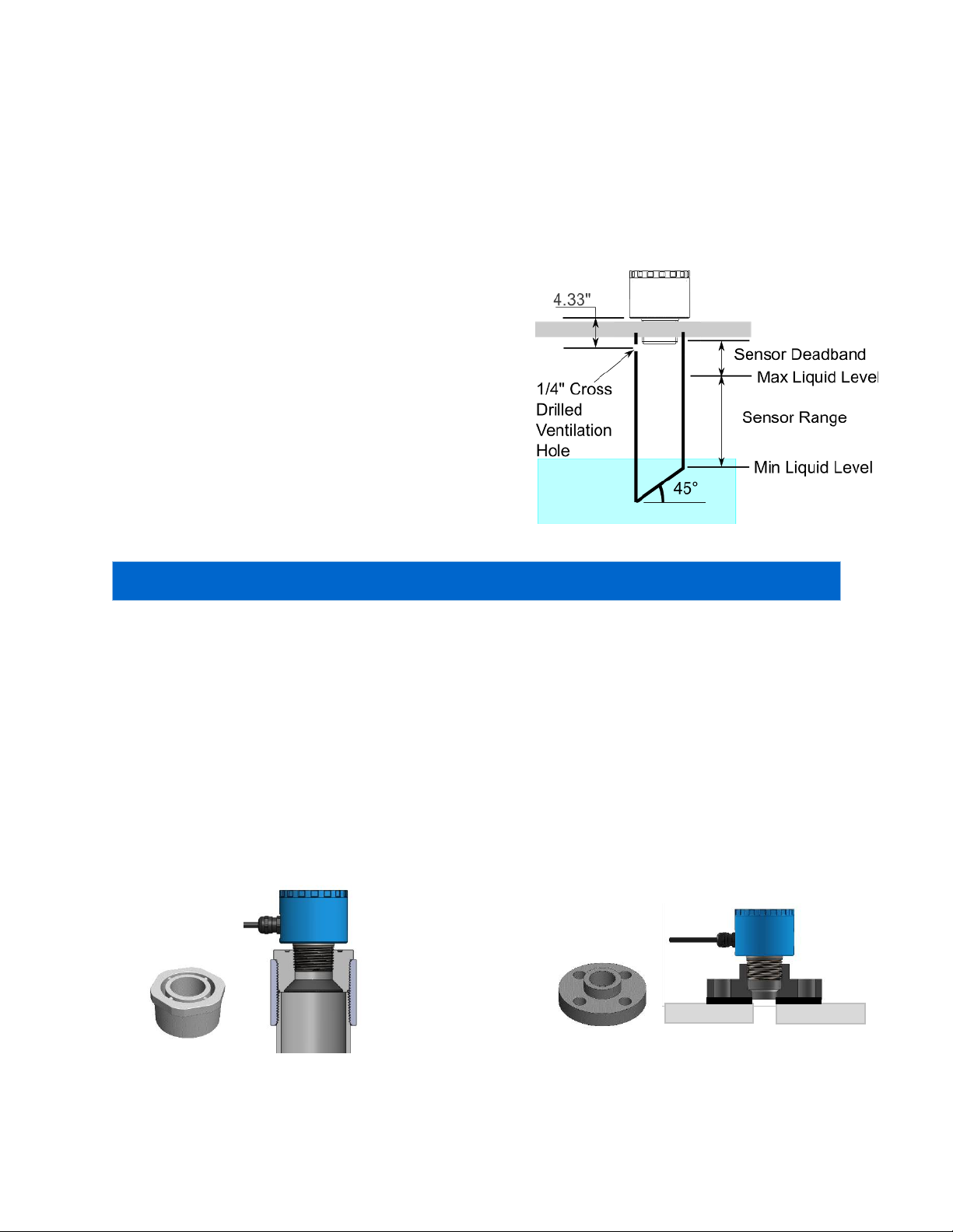
The ultrasonic level sensor measures level or distance and has a 4-20 mA analog output and 4 digital outputs. It
is a robust option for level sensing that offers flexibility and precision. The device is configurable either by
push-button programming with a LED display or through a USB software interface.
2Features and Benefits
Non-contact continuous level measurement with analog output, four switches and control functions
for distance of up to 82.68” (2.1 m),
Fast programming through USB software interface or field-adjustable programming through push
button interface and display,
LED display indicates current measurement in inches or centimeters with 0.01” (1 mm) resolution,
Precise 12-bit 4-20 mA output with invert 20-4 mA option,
Four programmable relays each able to handle up to 200 mA peak load current,
Selectable signal processing, fluid compensation, failsafe features that enable optimization for
installation,
Robust all-metal enclosure with 316SS port for corrosive environments,
Automatic temperature compensation for accurate measurements.
3Table of Contents
1General Description .............................................................................................................................................2
2Features and Benefits..........................................................................................................................................2
3Table of Contents.................................................................................................................................................2
4Specifications .......................................................................................................................................................3
5Installation............................................................................................................................................................4
6Electrical Connection ...........................................................................................................................................7
7Display Elements..................................................................................................................................................7
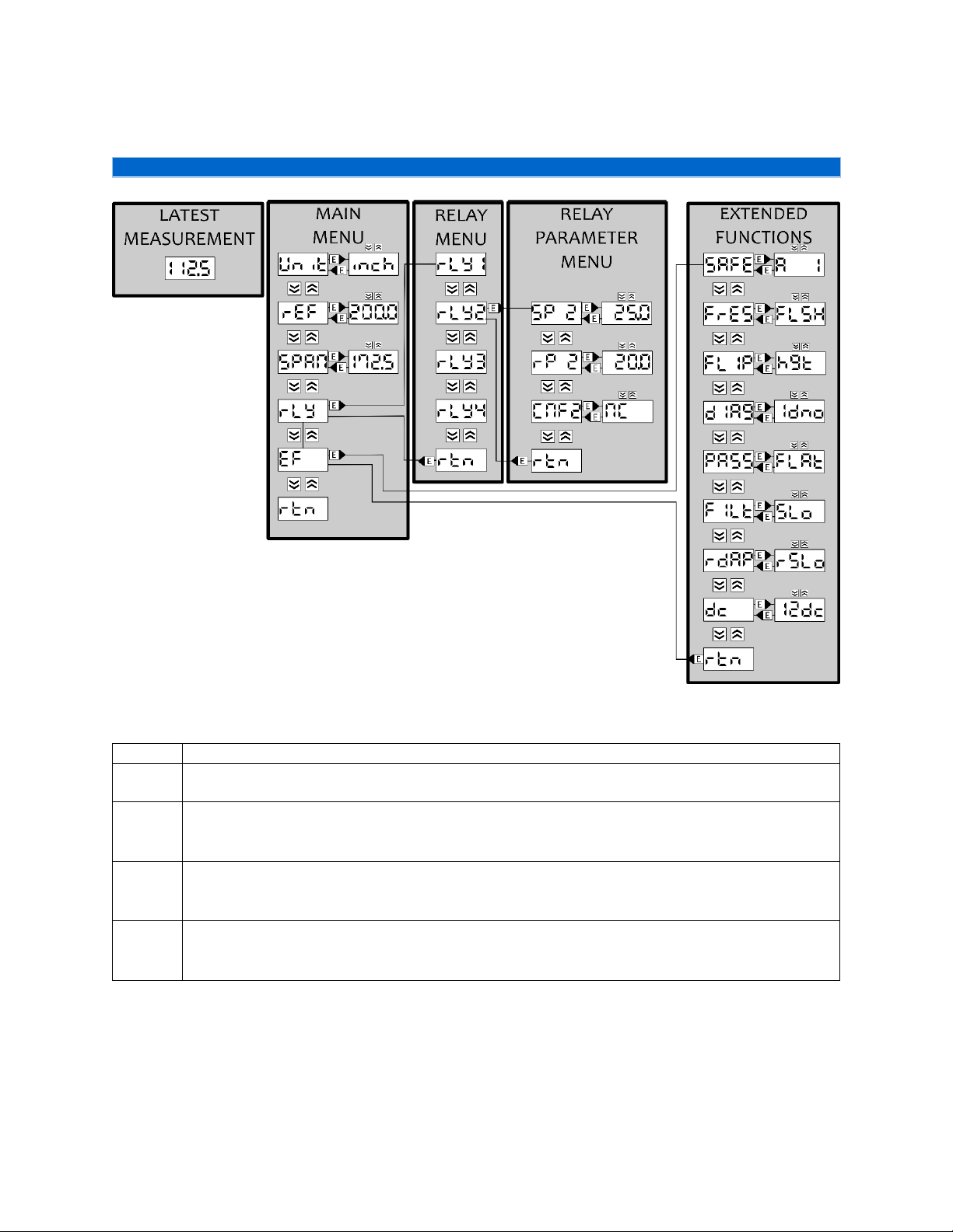
8Menu Hierarchy................................................................................................................................................... 8
9Parameter Selection .......................................................................................................................................... 10
10 Setting up the ULS ............................................................................................................................................. 12
11 Troubleshooting/FAQ ........................................................................................................................................ 19

ULS Owner’s Manual Rev 0.0 3
Released: 12/2021
4Specifications
Performance
Sensing accuracy1
0.5% of maximum operating distance (perpendicular to surface)
Sensing resolution
0.027” (0.69 mm)
Minimum operating distance3
5.4” (138 mm)
Maximum operating distance3
82.68” (2.1 m)
Temperature error2
2%
Transducer
Beam angle
12° ± 2°
Deadband3
4.33” (110 mm)
Ultrasonic frequency
112 kHz ± 4.5 kHz
Interface
User interface
Field adjustable (push buttons and display)
Software adjustable (Microsoft® Windows® with micro-B USB)
Display resolution
0.01”(1 mm)
Memory
Non-volatile
Electrical
Supply voltage
10 –30 VDC (100 mA maximum)
Maximum power consumption
1.2 W
Analog output
12-bit 4-20 mA output
Analog conversion error
<0.5%
Signal failsafe
2 mA, 4 mA, 20 mA, 22 mA or hold last
Hysteresis
Adjustable
Contact type
(4) Normally open SPST relays (48 VDC 200 mA peak load current)
Contact failsafe
Power loss: open
Environment
Ambient temperature
14 °F to 140 °F
(-10 °C to 60 °C)
Enclosure rating
IP 65
Enclosure material
Powder coated aluminum
Transducer material
Glass reinforced epoxy
Cable jacket material
PVC
Cable type
8-conductor, shielded
Process connection
1” NPT (Stainless Steel)
1- Accuracy specification in stable homogeneous standard environments (affected by temperature gradients, vapors,
supply voltage).
2- Thermal error specification defined for supply voltage of 12V and 24V. Error may be larger for other voltage inputs
or due to localized heating of tank or sensor.
3- Operating distances referenced from bottom of enclosure. Deadband referenced from sensor bottom.

4 ULS Owner’s Manual Rev 0.0
Released: 12/2021
5Installation
Locating the ULS and Application Considerations
The ultrasonic level sensor (ULS) is a non-contact distance measurement device that uses a sound wave that is
sent out from the bottom of the sensor to the target medium and returned back to the sensor. Due to the
operating principle of the ULS, the positioning of your device in your application needs to account for how the
sensor signal is transmitted to ensure proper measurement in all boundaries of operation.
Positioning of the Mount
As the sound wave generated from the device travels through air, it will grow in size. This
larger size creates a greater detection area at further distances. But, this detection area has
a drawback; it needs to be clear of any object or interference that could reflect the sound
wave.
The simplest approach is to position the mount away from walls and obstructions ensuring
that the obstructions are further than the beam radius using the following guideline:
Operating Range
Beam Radius
[feet]
[cm]
[inch]
[cm]
0.33
10
1
2.5
0.66
20
1.4
3.6
1
30
2
5.1
2
61
3.5
8.89
3
91
5
12.7
4
122
6.5
16.5
5
152
8
20.3
6
183
9.5
24.1
6.56
200
10
25.4
Orientation of the ULS
The device can accommodate perpendicularity errors between the thread axis and the
stationary fluid surface of ± 3°. As the orientation error increases, the device at first will lose
maximum range as the reflected signal strength decreases until no reflected sound is
transmitted to the device and the signal is not received.
Temperature
The device measures the level or distance by calculating the speed that the sound wave
travelled through the air and compensates for temperature variation using an internal
sensor. For accurate temperature measurement, there are two possible errors:
Error Source 1: Unit’s operating temperature is biased from external inputs.
Protect the unit from all external heat sources such as sunlight by using a thin,
reflective and low emissivity radiant barrier between the unit and the heat source.
Error Source 2: Tank temperature is not the same as ambient temperature.
Ideally keep tank and sensor at ambient temperature. A variation between
temperatures will cause the sensor to measure incorrectly.
NOTE: If signal is not received, a LOSS warning will appear on the display and will
default to failsafe settings. Generally, signal loss is caused by perpendicularity errors or
exceeding device’s maximum operating range.

ULS Owner’s Manual Rev 0.0 5
Released: 12/2021
Riser
After sending a sound wave, an ultrasonic sensor needs time to settle before it can start listening for the echo.
This time delay results in a distance that cannot reliably measure because it is not listening which is commonly
called the deadband, or minimum operating distance. If the target medium were to enter the deadband, the
device may not be able to consistently measure any target. It is mandatory that the unit is positioned away
from the target medium to avoid the deadband.
If your fluid tank needs to be fully filled, then the unit will need to be placed on a riser. The following is the
recommended riser guidelines.
Inner
Diameter
Maximum
Standpipe
Height
2 “ (5 cm)
4” (10 cm)
4 ” (10 cm)
8” (20 cm)
6 ” (15 cm)
12” (30 cm)
Foams
The surface quality of your target can impact the strength of the return signal causing sensing issues. If the
target surface has a foam layer, the amount of energy reflected in the return echo will be reduced. If possible,
mounting the unit in a location with minimal foam is the best practice. If the location is fixed, then using a
stilling well is necessary to avoid signal issues from foam.
Vapors
The device is configured for measurements in air. If the tank is closed and contains liquids that create vapors, it
will affect the accuracy of the measurement and may impact the maximum operating distance.
Tank Shapes
In some cases, the shape of the tank can cause inconsistent measurements by the way the signal reflects in the
tank. Validate that the unit is placed using the following guidelines:
1. Tank top
Do not install the unit in the center of a dome top tank. The ideal mount position for cylindrical
tanks is between 1/3 and 1/2 of the radius of the tank.
2. Tank bottom
Cone and rounded bottom tanks can have issues depending upon unit placement and fluid level.
The sensor signal may be lost if the fluid level lowers such that the angled or curved tank wall that
is exposed, which the sensor is directly above, reflects the sensor signal. The reflected sound
wave may not return to the unit or it can provide inaccurate measurements.
NOTE: The inner rim of the standpipe must be smooth and free of burrs.

6 ULS Owner’s Manual Rev 0.0
Released: 12/2021
Stilling Well
A stilling well is a pipe that goes below the minimum level of the fluid. The stilling well allows for easy
mounting: it can be near obstructions, reduces orientation requirements, avoids foam’s negative influence on
the sensor and reduces turbulence of the fluid.
A stilling well should have these features:
1. The stilling well pipe can made of any material,
2. Select a pipe that is 2” ID (51 mm) or greater,
3. Attach the ULS to the stilling well with a coupling and
a reducer bushing,
Use a plastic fitting such as P/N TM3216
4. The stilling well should exceed the sensing range of
the application,
The bottom of the pipe should always be
submerged to avoid foam from entering the pipe
5. A 1/4” cross drilled ventilation hole within the sensor
deadband,
6. A 45° angle cut on the bottom of the pipe if there is a
chance the fluid will lower more than the pipe
bottom,
7. The placement of the unit should be away from pumps as the level will vary during pump operation.
Mounts
For ease of installation, it is suggested that the non-metallic fittings be used. The unit should only be tightened
to finger-tight (15 inlb to 20 inlb). The following are the recommended fittings for your application:
1) Installation in existing fittings or with stilling wells
The isolation mount, P/N TM3216, provides excellent isolation between the sensor and a metallic
fitting. The isolation mount can be threaded directly into a 2” NPT adaptor, or it can be threaded
into a pipe adaptor and a threaded pipe.
2) Installation on a tank with a flange
The flange mount, P/N FM16, can be mounted directly to a tank. It uses a 4-bolt-circle pattern at
3.125” [79.4 mm]. Flange gaskets are sold separately.
NOTE: The pipe bottom should never be exposed to air. If exposed to air, the reflected sound may not
return to the sensor.
Figure 1: P/N TM3216 (left) and in a stilling well (right)
Figure 2: P/N FM16 (left) and on a tank (right)

ULS Owner’s Manual Rev 0.0 7
Released: 12/2021
6Electrical Connection
Depending upon your device configuration, some wire may not be used. Terminate unused wires.
Current Output Connection
Relay Output Connection
7Display Elements
The device has a 4-digit LED display with status LEDs on the side. The display shows either the current
measurement (in inches or centimeter) or the menu parameter. Following is a breakdown of the pushbutton
menu.
Wire Color
Description
RD
Red
+VDC (10-30 VDC 100 mA)
BK
Black
-VDC
WT
White
4-20 mA output
YL
Yellow
Relay Common
BL
Blue
Relay 1 (SSR1)
OR
Orange
Relay 2 (SSR2)
GN
Green
Relay 3 (SSR3)
BN
Brown
Relay 4 (SSR4)
M
Memorize
1
Relay 1 (SSR1) Make Status LED
>>
Up
2
Relay 2 (SSR2) Make Status LED
>>
Down
3
Relay 3 (SSR3) Make Status LED
E
Enter
4
Relay 4 (SSR4) Make Status LED
Set
Settings Mode LED
Inch
Inch Mode LED
USB
USB Communication Port

8 ULS Owner’s Manual Rev 0.0
Released: 12/2021
8Menu Hierarchy
Explanation of Run Mode
(blank)
Display off / quick press any key to wake up screen.
190.5
Latest measurement / displays latest filtered measurement based upon system units, reference
(height/level mode) or distance from sensor datum (distance mode).
VL
Under limit warning / measurement is below minimum operating distance. If it persists,
Ensure no object (burr, weld, target) within deadband,
Ensure unit is not over-tightened.
OL
Over limit warning / measurement is above maximum operating distance. If it persists,
Check installation to maximize operating distance,
Ensure target is within maximum operating distance
LOSS
Signal loss / sensor does not receive an acceptable signal. If it persists,
Ensure target is within operating distance,
Check unit alignment to target surface.
NOTE: The displayed parameters are an example. Your parameters may not be setup to the same values.

ULS Owner’s Manual Rev 0.0 9
Released: 12/2021
Explanation of Menus
Explanation of main menu
vnit
System unit setting / selection between inches [inch] and centimeters [cent].
rEF
Zero reference parameter defines zero when in level measurement mode. Used for defining the 4
mA output and acts as a relay distance parameter limit. See Setting the Zero Reference Value for
details.
SPAN
Maximum level for fluid sensing using reference parameter as zero. Used for defining the 20 mA
output and acts as a relay distance parameter limit. See Setting the Span Value for details.
rLY
Relay menu / selection opens relay menu.
EF
Extended functions / selection opens extended functions menu.
rtn
Exit main menu and return to current measurement.
Explanation of relay menu
rLY1
Relay 1 parameter menu / selection opens the relay 1 parameter menu.
rLY2
Relay 2 parameter menu / selection opens the relay 2 parameter menu.
rLY3
Relay 3 parameter menu / selection opens the relay 3 parameter menu.
rLY4
Relay 4 parameter menu / selection opens the relay 4 parameter menu.
rtn
Exit relay menu and return to main menu.
Explanation of relay parameter menu
SPx
Set point parameter for relay [x] / selection shows the current reset point with up and down
arrows for adjustment.
rPx
Reset point parameter for relay [x] / selection shows the current reset point with up and down
arrows for adjustment.
CnFx
Switch configuration parameter for relay [x] / selection opens the configuration of the relay with
options of normally closed [NC], normally open [NO], or off [OFF].
rtn
Exit relay parameter menu and return to relay menu.
Explanation of extended functions menu
SAFE
Fail-safe analog output / selection of fail-safe 2 mA (A 1), 4 mA (A 2), 20 mA (A 3), 22 mA (A 4), or
hold.
FrES
Factory reset / selection will go to additional confirmation to rewrite over the current settings in
temporary memory.
FLIP
Flip the measurement mode / selection will show current setting. Changing current setting will
turn off all relays.
dIAg
Diagnostic menu for device and OS information for troubleshooting.
PASS
Pass-band filter / selection for a tight pass-band (FLAt) or looser pass-band (FLUC)
FILT
Running-mean filter / selection of a 3 samples average (FStr), 9 sample average (FAST), or 30
sample average (Slo).
rdAP
Relay damping / selection of a 5 second delay to relay switching (rSLO) or a 0.5 second delay to
relay switching (rFST).
dc
Supply voltage temperature compensation / selection optimizes temperature compensation
based upon the input voltage supply: 12 DC (12dc) or 24 DC (24dc).
rtn
Exit extended functions menu and return to main menu.
NOTE: The measurement mode (level or distance) affects the relay operation. Select measurement mode
prior to setting up relays. See Selecting your Measurement Mode for more details.

10 ULS Owner’s Manual Rev 0.0
Released: 12/2021
9Parameter Selection
During parameter setting, the unit will continue to operate. Changes to parameters will change the temporary
memory for the parameter. All settings that are not saved to memory are temporary and will be reverted after
a power cycle.
General Setting Features
When setting a parameter the following steps need to occur:
1
Go to parameter
If display is off, press any key to turn it on.
Press [E] to enter the main menu or sub
menus.
Scroll using [ ] or [ ] until the desired
parameter name is displayed.
2
Adjust parameter value
Press [E] to enter the adjustment of the
parameter.
Press [ ] or [ ] until the desired value is
displayed.
NOTE: A short press has small increments and a
long press has larger increments.
Press [E] to store the adjustment to
temporary memory.
3
Save parameters to memory
WARNING
All adjusted parameters are stored in
temporary memory which will not be retained
after power loss.
To save all parameters to memory, press
and hold [M] for 5 seconds.
Screen will flash EEPr to indicate saving
and return to Run Mode.
Returning to Run Mode
Wait 30 seconds without no input to return to run mode ,
Or, press [ ] or [ ] until [rtn ] is displayed and press [E]. Repeat until current measurements are
displayed,
Vnit
ref
205.0
204.0
EEPr

ULS Owner’s Manual Rev 0.0 11
Released: 12/2021
Navigating between Menu Levels
1
Go into main menu
Press [E] to enter the main menu.
Press [ ] or [ ] until the sub-menu is
displayed on screen (from main menu [rLY]
or [EF] are the names for higher menu
levels).
2
Go to parameter sub menu
Press [E] to enter the parameter sub menu.
NOTE: The first parameter of the relay menu
will be displayed [rLY1].
NOTE: The first parameter of the extended
functions menu is displayed (either
[SAFE] or [FSEt] will be displayed).
3
Return to a lower menu level
To exit out of a menu, either
-Wait 30 seconds for display to return to
measurement,
-Press [ ] or [ ] in the menu until return
[rtn ] is displayed. Press [E] to return to
previous level.
Vnit
EF
SAFE
rtn
EF

12 ULS Owner’s Manual Rev 0.0
Released: 12/2021
10 Setting up the ULS
Configuring the System Units
1
Go to the parameter
Press [E] to enter the main menu and scroll with [ ] or [ ] until the unit
parameter [unit] is displayed.
Vnit
2
Adjust parameter value
Press [E] to adjust the system unit parameter value. Scroll with [ ] or [ ] to the
option and press [E] to choose it:
inch = inch units,
cent = centimeter units,
rtn = keep previous settings and return to previous menu.
inch
cent
rtn
3
Save parameters to memory
To save all parameters to memory, press and hold [M] for 5 seconds.
Screen will flash EEPr to indicate saving and return to Run Mode.
EEPr
Return to Run Mode
To exit out of a menu, either
-Wait 30 seconds for display to return to measurement,
-Press [ ] or [ ] in the menu until return [rtn ] is displayed. Press [E] to return to previous level.
Setting the Zero Reference Value
The zero reference is a necessary parameter for device operation. It
defines the point of reference for all displayed levels, it acts as the low
level indication (4 mA) and is the zero reference for digital outputs. To
get an accurate zero reference, you should validate two dimensions:
DIM 1: The fluid low level to the top of the mount,
DIM 2: The gap between the mount and the bottom of the blue ULS
enclosure.
1
Go to parameter
Press [E] to enter the main menu and scroll with [ ] or [ ] until the reference
parameter [rEF] is displayed.
ref
2
Adjust parameter value
Press [E] to adjust the zero reference parameter value. Press [ ] and [ ] to
adjust parameter value.
NOTE: The setting will show the current reference parameter value in temporary
memory.
Press [E] to leave the parameter setting menu.
205.0
3
Save parameters to memory
To save all parameters to memory, press and hold [M] for 5 seconds.
Screen will flash EEPr to indicate saving and return to Run Mode.
EEPr
NOTE: All displayed parameter values will match the unit parameter value in program memory.

ULS Owner’s Manual Rev 0.0 13
Released: 12/2021
Setting the Span Value
The span setting is the maximum fluid level value indicated through the analog output. It uses the fluid low
level (ref) as a zero reference point. The span must be a positive number and the maximum value is limited to
ensure that the span does not go into the device’s minimum operating distance, or deadband.
1
Go to parameter
Press [E] to enter the main menu and scroll with [ ] or [ ] until the span
parameter [SPAN] is displayed.
SpAN
2
Adjust parameter value
Press [E] to adjust the span value parameter value and use [ ] and [ ] to adjust
parameter value.
NOTE: The setting will show the current reference parameter value in temporary
memory.
Press [E] to leave the parameter setting menu.
190.0
3
Save parameters to memory
To save all parameters to memory, press and hold [M] for 5 seconds.
Screen will flash EEPr to indicate saving and return to Run Mode.
EEPr
Setting up your Relays
The relays change state from their normal state when the measurement reaches the set point (SPx) value and
return to their normal state when the measurement lowers to the reset point (rPx) value. This switching
function is normally called hysteresis function. The hysteresis in the switching function means that the reset
point is lower than the set point. The switch can be configured (CnFx) as either normally open (NO), normally
closed (NC), or off (OFF).
As the device can operate either in level or distance mode (see Selecting your Measurement Mode), it is
advisable to view the diagrams below to understand what a set point and reset point are in relation to the
measurement for your configuration. .
NOTE: The reset point cannot be a higher value than the set point and have a fixed minimum hysteresis of
20 mm (0.79”).

14 ULS Owner’s Manual Rev 0.0
Released: 12/2021
The following list defines some example relay configurations for the level
sensing mode:
High Alarm is on when the tank is full and turns off after the level drops.
For a level sensor when the level rises past the rising level set point value,
the electrical connection is made and the high alarm is ON. The relay will de-
energize (OFF) when levels falls below the reset value and the high alarm
turns OFF. It is in a normally open (NO) configuration.
Low Alarm is the opposite of the high alarm relay. It is a NC configuration
and it remains connected (ON) until the level rises above a set point value,
which breaks the circuit (OFF). When the level falls below the falling level set point value, the switch
connects the circuit (ON) again.
Fill operations are used when the tank level is approaching empty. For a level sensor, the relay is set to a
normally closed (NC) configuration. The circuit remains connected (ON) until the level reaches the fill off
value, which breaks the circuit (OFF). When the level falls below the falling value, the relay returns to
normally closed which makes the circuit (ON). This remains ON until the level again reaches the set point
value.
Drain is opposite of the fill operation. The relay is in the NO configuration. It makes the circuit (ON) when
the level reaches the high point and is broken when the level reaches below the low setting.
1
Go to parameter
Press [E] to enter the main menu and scroll with [ ] or [ ] until the relay
parameter [rLY] is displayed.
rLy
2
Navigate to parameter menu
Press [E] to enter the relay menu and scroll with [ ] and [ ] to find relay
number [rLYx] that needs adjustment.
Press [E] to enter the relay x’s parameter menu.
NOTE: x indicates the relay number displayed. It can range from 1 to 4.
rLy1
rLy2
rLy3
rLy4
2
Go to and adjust relay x’s parameter value
Press [ ] and [ ] to scroll to one of the following relay parameters:
SP x = set point x,
rP x = reset point x,
CnFx = relay configuration x,
-Normally open (NO), normally closed (NC) or off (OFF)
configurations.
rtn = keep previous settings and return to previous menu.
Press [E] to enter relay x’s parameter menu and adjust as desired. Press [E] to
return to the previous menu.
NOTE: x indicates the relay number displayed. It can range from 1 to 4.
5P1
rP1
CnF1
rtn
3
Save parameters to memory
To save all parameters to memory, press and hold [M] for 5 seconds.
Screen will flash EEPr to indicate saving and return to Run Mode.
EEPr

ULS Owner’s Manual Rev 0.0 15
Released: 12/2021
Defining your Failsafe Mode
If the unit is not able to get a consistent measurement, the analog output will default to a failsafe value. The
failsafe value is an output value that notifies the user or the control system that the unit is having difficulty
getting a reliable measurement that passes the validation filter.
To adjust the failsafe value the following steps need to occur:
1
Navigate to the extended functions menu level
Press [E] to enter the main menu and scroll with [ ] or [ ] until the extended
functions [EF] is displayed. Press [E] to enter the extended functions menu
EF
2
Navigate to parameter menu
Scroll [ ] and [ ] until the failsafe [SAFE] menu option is displayed and press [E]
to enter the fail-safe sub menu.
NOTE: If you are using a relay only model the fail-safe menu will not show. Relay
failsafe is to hold the previous value.
SAFE
3
Adjust parameter value
The initial displayed value is the current setting. Press [ ] and [ ] and [E] to set
the function:
[A 1] = 2.0 mA,
[A 2] = 4 mA,
[A 3] = 20 mA,
[A 4] = 22 mA,
[HOLd] = hold last value,
[rtn] = keep previous setting and return to previous menu.
A 1
A 2
A 3
A 4
HOLd
rtn
4
Save parameters to memory
To save all parameters to memory, press and hold [M] for 5 seconds.
Screen will flash EEPr to indicate saving and return to Run Mode.
EEPr
Returning to Factory Defaults & Saving to Memory
The unit can be returned to the as-received defaults through the factory reset menu.
1
Navigate to the extended functions menu level
Press [E] to enter the main menu and scroll with [ ] or [ ] until the extended
functions [EF] is displayed. Press [E] to enter the extended functions menu.
EF
2
Navigate to parameter menu
Press [ ] and [ ] to scroll until the factory reset [FSet] menu option is
displayed. Press [E] to enter the factory reset sub menu.
F5Et
3
Reset all parameter values
To confirm flashing of stored parameters, press [YES].
To exit without factory reset, press [NO].
YE5
NO
4
Save parameters to memory
The factory set parameters are stored on temporary memory and will be lost
after a power cycle. To save them to memory, press and hold [M] for 5 seconds.
Screen will flash EEPr to indicate saving and return to Run Mode.
EEPr
NOTE: In failsafe mode, the measurement output will indicate loss [LOSS] to indicate a lost measurement.
NOTE: Returning to factory defaults is temporary if you do not save parameters to memory.

16 ULS Owner’s Manual Rev 0.0
Released: 12/2021
Selecting your Measurement Mode
The device can indicate either the measured level or distance based upon a user-configurable setting in the
extended functions. As the measurement mode parameter alters the display indication, analog output and
digital outputs, it is best to select this mode before configuring your relays.
Level measurement mode
In the level measurement setting, the output is linked to a tank
level. As the tank level increases, the analog output increases and
as the level decreases so does the analog output.
In this configuration the reference parameter acts as the analog
zero output, or 4 mA, and the span parameter acts as the analog
full scale output, or 20 mA. For the switching functions, the set
point is based upon rising level and the reset point is based upon
falling level.
Distance measurement mode
In the distance measurement setting, the measurement is
referenced from the bottom of the sensor enclosure. As the
distance measurement increases the analog output increases and
as the distance decreases so does the analog output.
In this configuration, the reference parameter acts as the analog
full scale output, or 20 mA, and the span parameter acts as the
analog zero output, or 4 mA. For the switching functions, the set
point will trigger with increasing distance and the reset point will
act when distance is decreasing.
The following steps will adjust the measurement mode:
1
Navigate to the extended functions menu level
Press [E] to enter the main menu and scroll with [ ] or [ ] until the extended
functions [EF] is displayed. Press [E] to enter the extended functions menu
EF
2
Navigate to parameter menu
Press [ ] and [ ] to scroll until the flip logic mode [FLIP] menu option is
displayed. Press [E] to enter the flip logic sub menu.
FLIP
3
Adjust parameter value
The initial displayed value is the current setting. Scroll with [ ] and [ ] and set
[E] the function:
[Hgt] = level measurement,
[dISt] = distance measurement,
[rtn ] = return to previous menu.
Hgt
dI5t
rtn
4
Save parameters to memory
To save all parameters to memory, press and hold [M] for 5 seconds.
Screen will flash EEPr to indicate saving and return to Run Mode.
EEPr
NOTE: All relay values are turned off when switching between modes.

ULS Owner’s Manual Rev 0.0 17
Released: 12/2021
Adjusting the Filters
The device has digital filters to condition the output which is a compromise between stability and
responsiveness. It is possible to adjust the filter settings to better suit your application. The two filters are a
pass-band filter and a moving average filter.
The pass-band filter accepts any reading that is within a range of the previous averaged measurement. It is
used to minimize large amplitude noise that is present with turbulent or sloshing fluid. The following steps
allow you to adjust the pass-band filter:
1
Navigate to the extended functions menu level
Press [E] to enter the main menu and scroll using [ ] or [ ] until the extended
functions [EF] is displayed. Press [E] to enter the extended functions menu.
EF
2
Go to parameter
Press [ ] and [ ] until the pass-band filter (PASS) menu option is displayed.
Press [E] to enter the flip logic sub menu.
PASS
3
Select parameter value
The initial displayed value is the current setting. Scroll with [ ] and [ ] and set
[E] the function:
[FLAt] = narrow pass-band used to minimize noise,
[FLUC] = large pass-band used to accommodate fluid sloshing/turbulence,
[rtn ] = return to previous menu.
Press [E] to store new value in RAM or press [E] on [rtn] to keep previous value.
FLAT
FLvC
Rtn
4
Save parameters to memory
To save all parameters to memory, press and hold [M] for 5 seconds.
Screen will flash EEPr to indicate saving and return to Run Mode.
EEPr
The moving average filter is a filter that takes the average of certain amount of previous measurements
starting with the latest. It reduces short term fluctuations at the expense of step response time. The following
steps will modify the running mean filter:
1
Navigate to the extended functions menu level
Press [E] to enter the main menu and scroll with [ ] or [ ] until the extended
functions [EF] is displayed. Press [E] to enter the extended functions menu.
EF
2
Go to parameter sub menu
Press [ ] and [ ] to scroll until the moving average filter [FILt] menu option is
displayed and press [E] to enter the filter sub menu.
FILT
3
Select parameter value
The initial displayed value is the current setting. Scroll with [ ] and [ ] and set
[E] the function:
[SLO ] = 10 second averaging window,
[FAST] = 3 second averaging window,
[FSTr] = 1 second averaging window,
[rtn ] = keep previous settings and return to previous menu.
SLO
FAST
FSTR
rtn
4
Save parameters to memory
To save all parameters to memory, press and hold [M] for 5 seconds.
Screen will flash EEPr to indicate saving and return to Run Mode.
EEPr

18 ULS Owner’s Manual Rev 0.0
Released: 12/2021
Selecting the Relay Damping Value
In some application, the fluid level may oscillate causing relay chatter, repeated toggling of the digital outputs
on and off. To mitigate this problem, the device has a minimum relay delay of 0.5 seconds. If the measurement
remains at a value that would cause the relay to flip, it will do so once the relay damping timer has elapsed.
The following steps will adjust the amount of the delay, or relay damping value:
1
Navigate to the extended functions menu level
Press [E] to enter the main menu and scroll with [ ] or [ ] until the extended
functions [EF] is displayed. Press [E] to enter the extended functions menu.
EF
2
Navigate to parameter menu
Press [ ] and [ ] to scroll until the relay damping [rDAP] menu option is
displayed and press [E] to enter the relay damping sub menu.
rDAP
3
Adjust parameter value
The initial displayed value is the current setting. Scroll with [ ] and [ ] and set
[E] the function:
[rSLO] = 5 second delay,
[rFST] = 0.5 second delay,
[rtn ] = keep previous setting and return to previous menu.
rSLO
RFST
Rtn
4
Save parameters to memory
To save all parameters to memory, press and hold [M] for 5 seconds.
Screen will flash EEPr to indicate saving and return to Run Mode.
EEPr
Selecting your Temperature Compensation
There is an additional input supply voltage temperature compensation parameter to improve the steady state
temperature bias caused by different supply voltages. There are two input supply voltage (12 and 24 Vdc) that
the device can compensate for temperature bias.
The following steps will adjust the temperature compensation parameter:
1
Navigate to the extended functions menu level
Press [E] to enter the main menu and scroll with [ ] or [ ] until the extended
functions [EF] is displayed. Press [E] to enter the extended functions menu.
EF
2
Navigate to parameter menu
Press [ ] and [ ] to scroll the voltage temperature compensation [dc] menu
option is displayed and press [E] to enter the sub menu.
dc
3
Adjust parameter value
The initial displayed value is the current setting. Scroll with [ ] and [ ] and set
[E] the function:
[12dc] = 12 VDC compensation,
[24dc] = 24 VDC compensation,
[rtn ] = keep previous value and return to previous menu.
12dc
24dc
Rtn
4
Save parameters to memory
To save all parameters to memory, press and hold [M] for 5 seconds.
Screen will flash EEPr to indicate saving and return to Run Mode.
EEPr

ULS Owner’s Manual Rev 0.0 19
Released: 12/2021
11 Troubleshooting/FAQ
The following are the most common issues and the procedures that can resolve them.
Powering the Sensor Properly
1. Check the power supply specs.
-The device requires a 100 mA, 10 to 30 VDC power supply.
2. Unplug the power supply.
3. Respectively connect the red and black wires to the positive and negative terminals.
4. Plug in the power supply.
NOTE: Check the unit is powered either by checking the display, checking the output, or measuring the current
consumption through the power supply lines.
Display Warnings
Sensor display shows LOSS
The display will indicate loss (LOSS) when the unit does not receive a consistent measurement of the target.
The common causes of inconsistent measurements are installation errors (orientation of sensor), poor target
surface quality (foam, turbulence or fluid sloshing), or exceeding the maximum operating distance.
Sensor display shows UL
The display indicates under limit (UL) when the unit determines that the echo return is within the minimum
operating distance, or deadband. The unit will continue to output but may not be reliable at these ranges.
1. The distance from bottom of enclosure to maximum target height must be greater than the minimum
operating distance. If the target would enter into the minimum operating distance, then it is
suggested to use a riser to ensure proper operation.
2. If the target is not in the deadband, then double check that no burrs or edges that could cause a signal
reflection.
Sensor display shows OL
The display indicates over limit (OL) when the unit measures that the echo return exceeds its maximum
operating range. The unit will continue to operate but may not consistently measure if the target is outside the
maximum range.
1. The distance from bottom of enclosure to minimum target height must be less than the maximum
operating distance. If the target exceeds the maximum operating distance, then the unit may not
reliably operate.
2. If the distance from bottom to target does not exceed the maximum operating distance, then
common errors can be orientation of sensor or target surface quality.
Measurement Errors
Sensor goes to LOSS/failsafe
A unit that goes to LOSS/failsafe indicates that it is generally at extremes of operation.
If fluid is close to the unit, the fluid may have entered the minimum operating range, or deadband. When it
enters the deadband, the unit may not measure correctly or consistently enough for it to keep to a value.
1. Ensure in all operation cases that no fluid enters the deadband.
If the target is far away from the unit, the problem may be that the signal is not strong enough.

20 ULS Owner’s Manual Rev 0.0
Released: 12/2021
2. Verify installation and operation conditions.
-Loss of range indicates the unit is not receiving the signal clearly. Common sources of errors are
the installation, surface quality, propagating medium.
Analog Output Errors
Sensor indicates 0 mA
Check that the unit is properly powered (see Powering the Sensor Properly). If it is still 0 mA, an output of 0 mA
generally indicates an open circuit.
1. Check the connection between your measuring system and the transmitter.
If your system only shows values between 4 and 20 mA, then it is possible that the sensor may be out of the
measuring range.
2. Validate that the current is outputting by integrating a multimeter in series with your measurement
system.
Sensor output greater than 22.5 mA
If the unit is outputting more than 22.5 mA, there is a short circuit.
1. Immediately check the connections for a short circuit. The maximum output is failsafe value of 22 mA.
Anything greater indicates a faulty setup.
Output decreases with increasing fluid height
The unit’s measurement mode is configured to distance mode. Follow the steps outlined in Selecting your
Measurement Mode to adjust the parameters.
Digital Output Errors
Relay chatters on/off repeatedly
The relay chattering is likely caused by sloshing or turbulence in the target.
1. Increasing the hysteresis between switch set point and reset point should resolve the problem,
2. If increasing hysteresis is not possible, then increasing relay damping may resolve problem or minimize
chatter.
Table of contents