Page 2
90 mm
45 mm
37 mm
90 mm
45 mm
159 mm
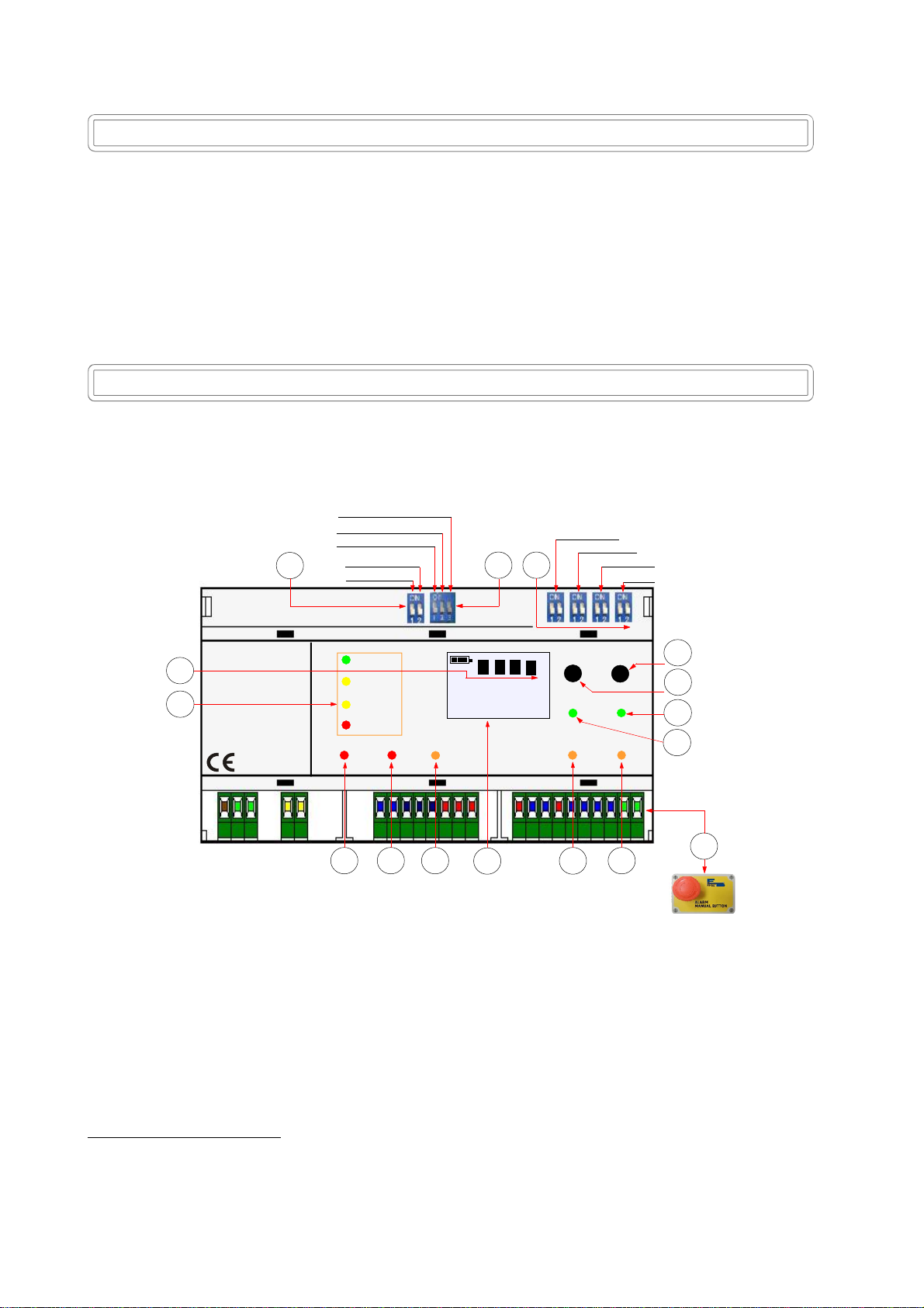
FaultMain AlarmPre Alarm BX449F probes battery
RESET TEST
Explosive Toxic
000LEL
ppm
1 2 3 4
OVER LOAD
1
2
3
4
OpenLine
CloseLine
FIRE
Alarm
Precautions
CHECK the integrity of the unit after having removed it from the box.
Check that the data written on the box correspond to the type of gas used.
When doing the electrical connections, follow the drawing closely.
Any use of the detector for purposes other than the intended one is considered improper,
and as a result of which BEINAT S.r.l. therefore disclaims any responsibility for possible
damages caused to people, animals or objects.
IMPORTANT: the functional test must not be carried out with the gas tap open as this does not guarantee
sufficient concentration to activate the main alarm.
TERMS and EXPECTATIONS: The installation of the BX449F control unit, its ordinary and extraordinary
maintenance, every six months, and its out of service removal at the end of the functional life guaranteed by
the manufacturer, must be carried out by authorized or specialized personnel.
Do not allow it to become wet.
The unit can be seriously damaged as it is not waterproof so when immersed in water or exposed to high
humidity levels.
Do not drop it.
Heavy knocks or falls during transportation or installation can damage the appliance.
Technical Specifications
Main power ........................................................................................... 110/240VAC 50/60Hz ±10%
Insulation ..................................................................................................................... Class II
Secondary Power Through Battery Max 2,2 Ah (Optional) ........................................................ 12 V ±10%
Battery charger max. 2.2 Ah ..................................................................................................... Controlled
Power demand ....................................................................................................... 11W max. 230 VAC
Power demand ........................................................................................................ 6W max. @ 12 VDC
Range of the contacts on the gas pre-alarm, alarm and fault relay ............................... 10A 250 VAC resistive
Range of the contacts on the fire alarm relay ............................................................ 10A 250 VAC resistive
Detection
Pre alarm ......................................................................................... 13% of L.E.L. or 200 ppm for CO
Final alarm .............................................................................. Set to 20% of L.E.L. or 300 ppm for CO
The LEL is calcuaded for Gas Methane .................................................................... 5000 ppm = 5% V/V
Data refresh ............................................................................................................................ 2 ms
OXYGEN alarm ............. <Oxygen deficiency,> Excess Oxygen ......................... see thresholds on page 5
Monitored events .................................................................................... Through backlit color display
Zones ............................................................................................................................................ 4
Number of connectable gas sensors ......................................................................... 4 (1 for each zone)
Types of conventional gas sensors ....................... Semiconductor, Catalytic, Electrochemical cell, Pellistor
Number of connectable fire sensors ....................................................................... 20 (5 for each zone)
Types of fire sensors connectable ......................... Optical smoke - fixed temperature - increment temperature
Micro-switches to include or exclude the gas sensors, Exclusion only for CO ....................... 1 for each zone
Microswitches to select the OXYGEN detection ................................................... ................ incorporated
Microswitches to display ............................................... ......................... Over Range and Under Range
Type of faults detected by fault circuit ..................................................... Interruption, short circuit, or wear
OVER LOAD Check .....................................................................................................1 for each sensor
OVER LOAD Check ............................................................................................................ 1 for battery
Input signal GAS................................................................................................. 4 ÷ 20 mA on 220 Ohm
Input signal FIRE....................... 2.2 VDC at rest, 8.7VDC in alarm, 13.92 VDC with short-circuited cables
Functioning temperature ................................................................................................. -10°C ÷ +60°C
Waiting, blinking time (warm-up) ................................................................................. About 2 minutes
Manual test ............................................................................................................................. Built in
Max. distance between sensors and unit ..................................................................................... 100 m
Max. distance between battery and unit.......................................................................................... 0,5 m
Cable diameter to connect the senors ....................................... .................................................. 1 mm2
Connection: The cable of connection of the sensor must not be installed together with the power cables.
Otherwise, make sure to use a shielded cable
Omega-type size DIN EN 50092 9 modules ................................................................................. 158*90*58
Degree of protection .................................................................................................................... IP20