tousek TURN 310 UF User manual

Installation- and Operating Instructions
Underoor operator TURN 310 UF
- 2 - tousek / E_TURN-310UF_43000203 / 19. 03. 2013
Important warning and safety notes for installation and operation
• These installation- and operating instructions form an integral part of the product “sliding gate operator”. They have been
specically written for professional installers trained and skilled in the trade and should be carefully read in their full length
before carrying out the installation. They describe the proper installation and operation of the sliding gate operator only,
not of the overall device “automatic gate”. After the installation this manual has to be handed over to the user.
• Installation, connection, adjustments, putting into operation, and servicing may only be carried out by trained professionals
in full accordance with these installation- and operating instructions.
• Before carrying out works at the gate-system, the power supply has to be turned off.
• The EU Machine Directive, laws and rules concerning the prevention of accidents, and laws and standards which are in
force in the EU and in the individual countries have to be strictly followed.
• The TOUSEK Ges.m.b.H. cannot be held liable for any claims resulting from disregards of the laws and standards in
force during the installation and operation.
• The packaging materials (cardboard, plastic, EPS foam parts and lling material etc.) have to be properly disposed of
in accordance with the applying recycling- and environmental procection laws. They may be hazardous to children and
therefore have to be stored out of children´s reach.
• The product is not suitable for installation in explosion-hazardous areas.
• The product may only be used in accordance with its original purpose, for which it has been exclusively designed, and
which is described in these installation and operating instructions. The TOUSEK Ges.m.b.H. rejects any liability if the
product is used in any way not fully conforming to its original purpose as stated herein.
• Before beginning with the installation the installer has to make sure that all mechanical components of the gate facility, like
carrier prole/rail, gate frame and panels, guiding elements etc. are sufciently supportive and resistant for the purpose
of gate automation.
• All electrical installations have to be made in full conformity with the applying rules and laws (e.g. using a fault current
circuit breaker, proper grounding etc.).
• An all-pole disconnecting main switch with a contact opening-gap of minimum 3 mm has to be foreseen
• The electric motor heats up during operation. Therefore the device should only be touched after it has cooled off.
• The TOUSEK Ges.m.b.H. rejects any liability for claims resulting from usage of the product in combination with compo-
nents or devices which do not fully conform to the applying safety laws and rules.
• Only original spare- and replacement parts may be used for repair of the product.
• The installer has to inform the user about all aspects of the automatic operation of the complete gate facility, as well as
about emergency operation. The installer further has to supply to the user all instructions relating to the safe operation
of the gate facility. The installation and operating instructions also have to be handed over to the user..
• Please notice that the warranty will not be applicable if the label with the engine number has been removed or
damaged.
Maintenance
• Before carrying out maintenance works at the gate-system, the power supply has to be turned off.
• Maintenance works may only be carried out by qualied personnel.
• Check the proper sensitivity setting of the ARS safety reverse system once a month.
• Check the proper function of the emergency release mechanism periodically.
• Check if all mounting screws are securely fastened periodically.
• Remove dirt deposits from the operator and gear rack periodically.
• All pivot and bearing points have to be greased periodically.
• Maintenance and servicing of the complete gate facility has to be carried out according to the gate builder´s/
installer´s instructions.
• At the end of each winter season you should rinse the operator with warm water.
This manual is the sole property of the TOUSEK Ges.m.b.H. and may not be made available to competitors. All rights reserved. No part of it may be reproduced without our prior
written permission. We will not accept liability for any claims resulting from misprints or errors. This edition of the manual replaces all earlier publications of the same.
EU - Manufacturer´s Declaration according Machine Directive 2006/42/EC:
The company TOUSEK Ges.m.b.H., based in Zetschegasse 1, A-1230 Vienna/Austria, hereby declares that the “Swing gate
operator TURN 310 UF” is made available only for the purpose of being built into a machine or of being joined with other
machines or machine components, and that it may not be put into operation until a declaration of conformity according to
the Directive 2006/42/EC has been issued for the whole machine.
The following directives and standards have been applied:
- Low Voltage Directive 2006/95/EC, incl. changes
- Electromagnetic Compatibility Directive 2004/108/EC, incl. changes
January 2012

tousek / E_TURN-310UF_43000203 / 19. 03. 2013 - 3 -
Characteristics TURN 310 UF
• for 230V a.c.
• max. weight of gate wings 400 kg
• max. wing size 3 m (from wing size of 2,5 m on an e-lock
is recommended
• galvanized sheet steel- or stainless steel housing
•
1. General Underoor operator TURN 310 UF
General features
The underoor operator TOUSEK TURN 310 UF is suitable for the automation of swing gates, whereas the full operating unit is
installed under the ground.
This operator was especially developed for swing gates in the private area, which are not exposed to continuous operation.
It distinguishes itself by it’s rather compact shape and the adjustable limit switches which are integrated in its housing.
The motor unit is installed in a massive sheet steel housing, which is optionally also available in stainless steel (TURN 310 UF/E).
This housing is constructed the way, that it also serves as bearing for the gate at the same time.
The gate weight (max. 400 kg) is carried by this bearing, and the motor-gearing unit can so be easily removed and installed without
dismounting the gate.
The operator ensures the blocking of the gate and so usually no e-lock is required. But according to the individual case of mounting,
an additional locking device may be necessary (at wings larger than 2,5 m we recommend the installation of an e-lock).
With a key for emergency release the gate can be opened manually in case of a power failure.
for connection an optional
terminal box (IP 66), which will be placed into
the operator housing, is available.
(see additional manual)
Technical data
Underoor operator TURN 310 UF
operating voltage 230V a.c., 50Hz wing weight max. 400kg
current consumption max. 1,5 A protection class IP66
max. turning angle 110º, optional > 110º Article no.
max. angular velocity 6º /s TURN 310 UF 11230100
max. torque 300Nm TURN 310 UF/E (stainless steel)11230110
operating factor 30% additional bracket for
180° opening angle 14120220
wing size max. 3m
Other
blocking in open and closed position • force adjustment through control unit • emergency release •
internal limit stops • optional: steel or stainless steel housing • additional bracket for opening angle
> 110° • terminal box IP66
•
Max. wing widths do neither apply to full-panel gates (but to stave or trellised gates) nor to non-horizontal gates!
• at wings larger than 2,5 m an e-lock is required!

- 4 - tousek / E_TURN-310UF_43000203 / 19. 03. 2013
Technical layout TURN 310 UF
2. Installation Underoor operator TURN 310 UF
1 underoor housing
1a bearing pin
1b motor fastening screws (6 x)
1c motor fastening nuts (4 x)
1d opening for connecting cable
1e openings for drainage
2 motor-gearing unit
2a grounding terminal
(grounding cable laid separately)
2b gearing shaft
mk motor cable
3 motor arm
3a fastening screw
3b adjustable limiting screw
(for adjustment of gate position closed)
optional: chain bracket (for turning angle > 110°)
K1 gate driver with pinion replaces (4)
K2 output pinion replaces motor arm (3)
K3 chain replaces lever arm (5)
gate frame
foresee PVC-pipe Ø 60-80 for drainage!
U-prole
(for inserting the gate wing)
1
1a
1b
1d
1e
2
1c
4
4a
4b
7
7a
5
8
mk
8a
8b
9
3
3a
3b
67b
2a
2b
optional: chain bracket
K1
K2
K3
4 gate driver
4a adjustable limiting hexagon
(for adjustment of gate position open)
4b fastening screw
5 lever arm (connects gate driver (4) with motor lever (3)
6 ball
7 gate bearing
7a emergency release mechanism
7b emergency release lever
8 housing cover
8a fastening screws (2x)
8b intakes for fastening screws (2x)
9 plastic covering
tousek / E_TURN-310UF_43000203 / 19. 03. 2013 - 5 -
Suggestion
• Before mounting we suggest to spray some protection wax all around the operator.
• After mounting please spray some protection wax on all parts inside the operator housing.
HINWEIS für den Benutzer
- 6 - tousek / E_TURN-310UF_43000203 / 19. 03. 2013
415
A
B
341
55
170
68
ground level
D
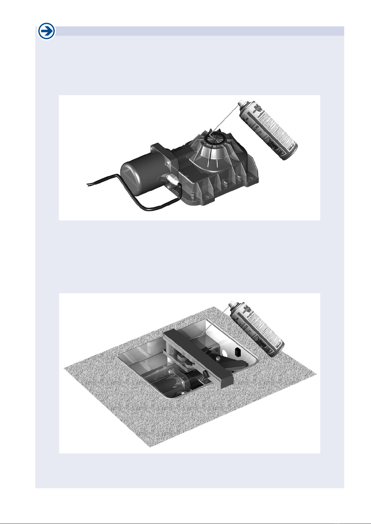
2a. Immuring the underoor housing Installation
• Before immuring the operator housing please make
take care, that free movement is assured for the full
opening angle of the gate.
• At mounting please make sure, that gate hinge and
bearing pin of the operator are perpendicular to each
other (point A and B).
• Before mounting please remove the motor-gearing
unit of the operator housing.
• The operator housing has to be immured in alignment with
the ground level and with attention to the below stated
measurements in a frost resistant way.
It is absolutely necessary to foresee a drainage!
Important: forsee a drainage!
• To avoid ooding of the operator through strong
rainshowers, snowmelt or the like, it is necessary
to provide a drainage system for optimal outow of
water.
• For that purpose connect PVC pipes with a dia-
meter of 60–80mm to the provided opening Don
both sides of the housing.
7
4
6
1a
7a
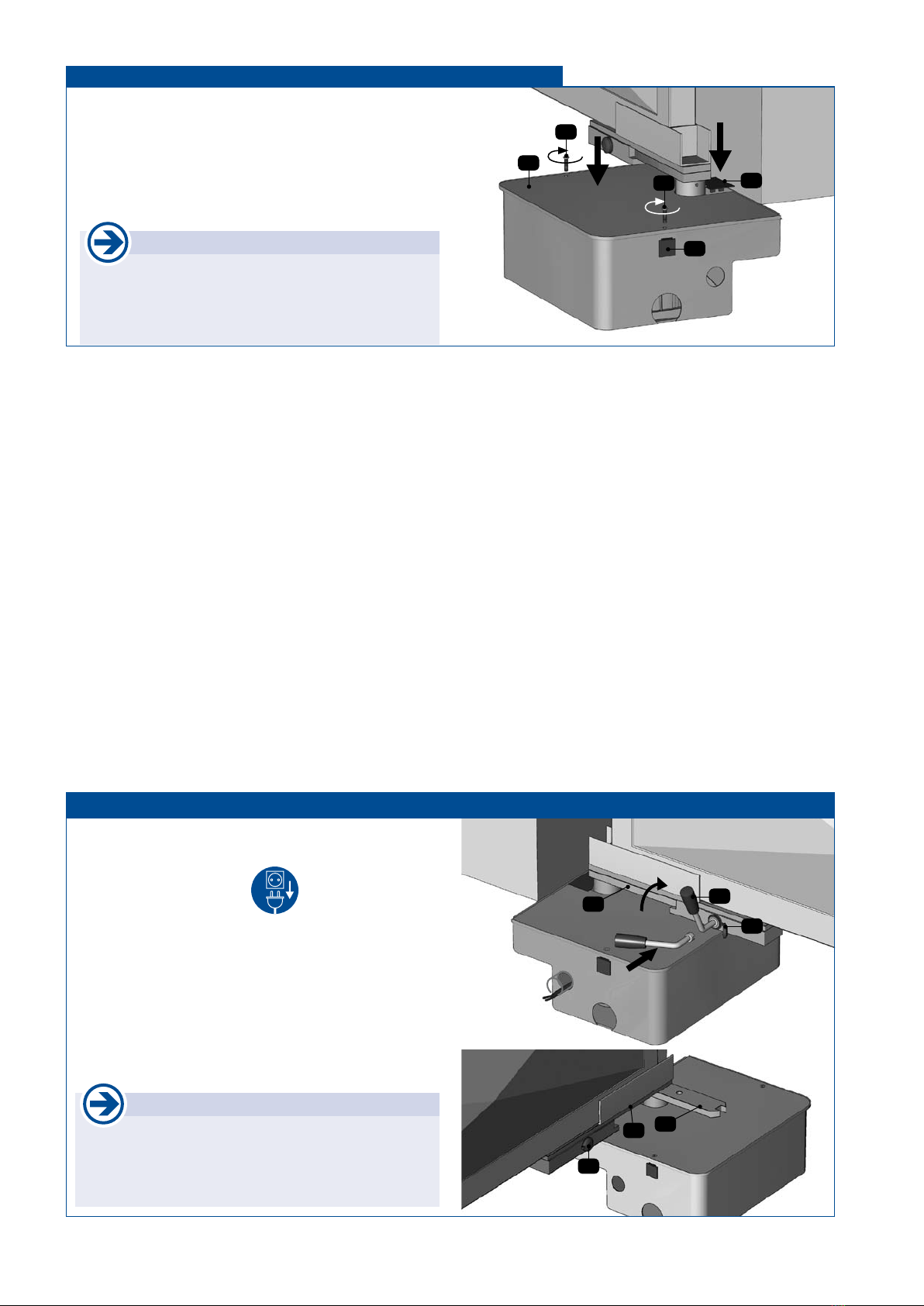
2b. Inserting gate driver and gate bearing Installation
• Important: Grease bearing pin (1a)!
• Put ball (6), gate driver (4) and gate bearing (7) at the
bearing pin (1a).
In case that gate driver and gate bearing have not been
assembled, insert the gate bearing (7) in the gate driver
(4) so that they form one unit.
Therefore the gate bearing (7) is turned in emergency
released state (see emergency release), till it is aligned
at the gate driver (4) as shown in the beside picture and
the lever of the emergency release mechanism (7a) may
engage in the gate driver.

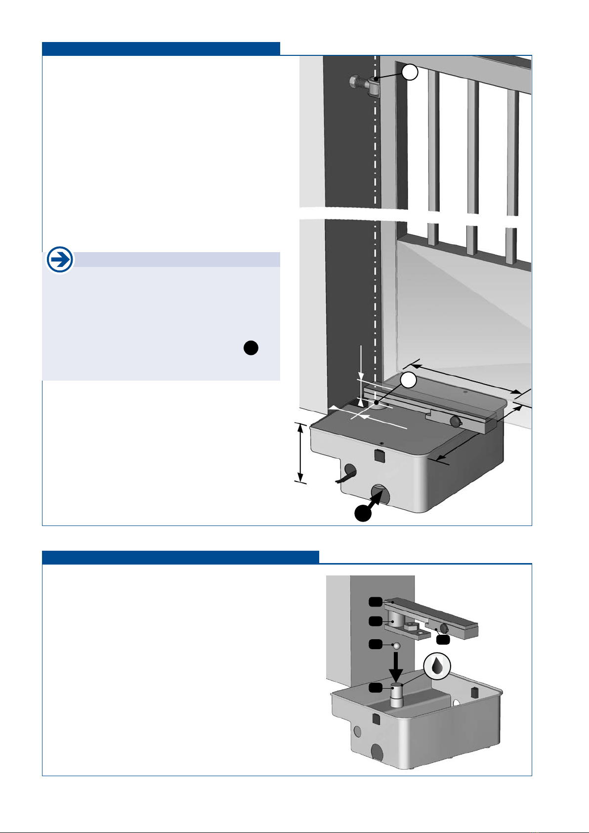
tousek / E_TURN-310UF_43000203 / 19. 03. 2013 - 7 -
cable opening
limiting piece
guiding rail b
b = width of gate frame
emergency release area
7
• Mounting with guiding rail
7a
• The gate frame can be mounted directly to the gate bearing or by using
an approx. 250 mm long guiding rail (U-prole).
In each case gate hinge and bearing pin have to be perpendicular
to each other (point A and B) and the gate wing has to be mounted
vertically.
• According to the way of mounting either connect the gate frame or the
guiding rail with the gate bearing (7). (Note: Take care that the emer-
gency release (7a) still works properly!)
If a guiding rail is used, insert the gate frame and adjust it vertical-
ly. Afterwards insert the limiting piece and weld it to the guiding rail.
It is recommended, to weld the guiding rail not onto the gate frame!
Es wird empfohlen die Führungshalterung nicht mit dem Torügel
zu verschweißen !
Note: For a ground clearance of more than 55 mm please insert a spacer
before mounting the gate/the guiding rail to the gate bearing.
• Checking the opening movement
Emergency release the operator (see emergency release) and fully open
and close the gate manually. Make sure that no undue friction occurs.
2c. Mounting of gate frame at the gate bearing Installation
emergency release area
7
• Mounting without guiding rail
7a
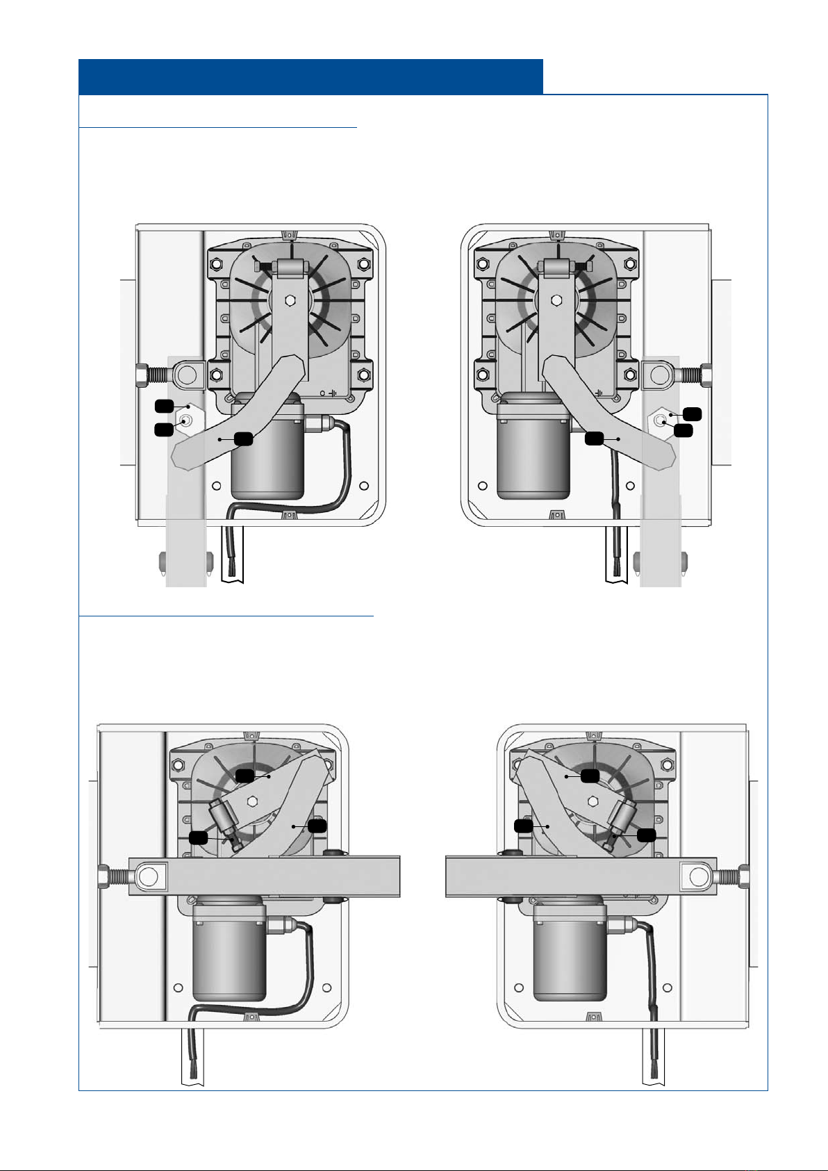
2d. Mounting the motor-gearing unit Installation
• Open the gate completely
• Pay attention to left- and right installation (see below gure).
Put the motor-gearing unit onto the 4 screws inside the
housing and secure it with the nuts.
left installation right installation
INTERIOR
approx. 68mm
approx.
55mm
A
B
7
7a

- 8 - tousek / E_TURN-310UF_43000203 / 19. 03. 2013
2a
mk
protective sleeve
ek
1d
2b
3
5
4
K1 K2
K3 K3a
CABLE RIGHT
operator
LEFT
operator
blue common common
black open close
brown close open
yellow/green grounding grounding
Attention
• At force adjustment please take care that all valid
safety standards and regulations are kept.
Important for chain operation
• Since the internal limits don’t come into effect at
chain operation you have to make sure, that oor
stops x the end positions gate opened and gate
closed.
• Alternatively Tousek piston rod travel limiters can
be used as well.
2e. Connection with operator Installation
Mounting of motor- and lever arm
• Put motor arm (3) onto gearing shaft (2b) and x it with a
screw.
• Important: Grease the pins of the lever arm (5) properly!
• Now turn the gate as far as the lever arm (5) can be inserted
in the openings of the gate driver (4) and the motor arm
(3). Please take care to insert the lever arm (5) as shown
in the picture (the bending of the arm always points
away from the gate axis, at left installation as well as
at right installation).
optional: mounting output pinion and chain
(for turning angle > 110°)
• Set output pinion (K2) on gearing shaft (2b) and x it with
a screw.
• Now put the chain (K3) around the gate driver (K1) and the
output pinion (K2) and close it with the chain lock (K3a).
• Important: The chain has to be greased carefully!
2f. Electrical connection and power adjustment Installation
• Before carrying out the electrical connections the po-
wer supply of the swing gate facility has to be turned
off.
• Note: For the grounding the motor a separate groun-
ding cable has to be laid.
• Connect the operator according to the manual of the con-
trol. Therefore insert motor cable (blue/brown/black) (mk)
and grounding cable (yellow-green) (ek) in a protective
sleeve and lead it in the foreseen cable opening (1d).
The separately laid grounding cable is xed directly at the
motor block with the help of a screw (2a).
• Connect various safety devices and accessories according
to their manuals (please pay attention to enclosed cable
plan).
• The force adjustment of the operator is carried out at the
control (see control manual).
tousek / E_TURN-310UF_43000203 / 19. 03. 2013 - 9 -
left installation right installation
INTERIOR
3
3b
53b
5
3
left installation right installation
INTERIOR
4a
4b 5
4a
4b
5
Adjustment of limiters for OPEN position
• Fully open the gate with the operator
• Now turn the hexagon (4a = limiter for open position) at the gate driver so far (loosen xing screw (4b)) that the lever
arm (5) touches the hexagon.
• Fix the hexagon (4a) in this position with the xing screw (4b).
Adjustment of limiters for CLOSED position
• Fully close the gate with the operator
• Now turn the limiting screw (3b= limiter for closed position) at the motor arm (3) so far that it touches the
lever arm (5).
• Depending on left- or right assembly, please take care that the limiting screw (3b) is correctly positioned in
the guiding of the motor arm (3) (see picture).
2g. Adjustment of internal limiters
(invalid for operators with chain: foresee external oor stops!) Installation
- 10 - tousek / E_TURN-310UF_43000203 / 19. 03. 2013
8
8a
8b
8a 9
7a
7b
4
7
7a
4
2h. Putting on the housing cover Installation
In case of a defect or power failure the operator can be
emergency released as follows:
• Turn off power supply!
•
Open plastic cap at the emergency release mechanism (7a).
• Insert emergency release lever (7b) as shown in the
drawing and turn it right till the gate bearing (7) is released
of the gate driver (4). Keep this position and release the
gate manually.
• To restore motor operation turn the gate until you can hear
that it has re-engaged.
• Put on the plastic cap again.
Note
• Installation, connection, taking into operation and
maintenance may only be carried out by qualied
professionals and with regard to this manual.
3. Note for the user - Emergency release (e.g. at power failure) TURN 310 UF
• After nishing the installation- and adjustment works put
the housing cover (8) on the underoor housing and x it
with 2 screws (8a) in the intakes (8b) at the sides of the
housing.
• Finally put on the plastic cover (9).
Note
• Before closing the housing please note the
suggestion on page 5.
tousek / E_TURN-310UF_43000203 / 19. 03. 2013 - 11 -
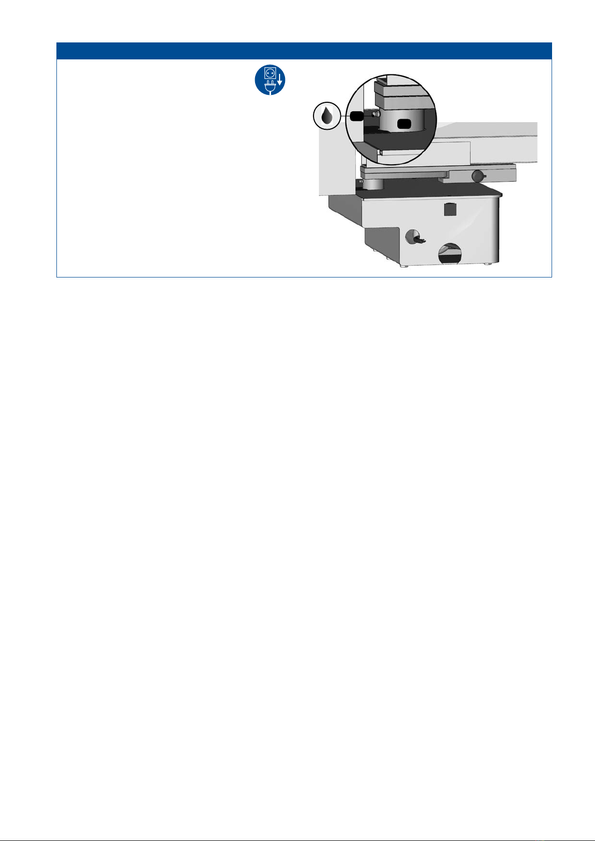
4
4c
Before carrying out maintenance works at
the gate-system, the power supply has to
be turned off!
• All pivot- and bearing points have to be greased pe-
riodically.
• For greasing the pivot point of the operator, the cylindrical
part of the gate driver (4) has to be foreseen with a tap
hole. In this tap hole the grease nipple (4c) for connection
of a grease gun is inserted.
• At the end of each winter season you should rinse the
operator with warm water.
4. Maintenance of the facility TURN 310 UF
- 12 - tousek / E_TURN-310UF_43000203 / 19. 03. 2013
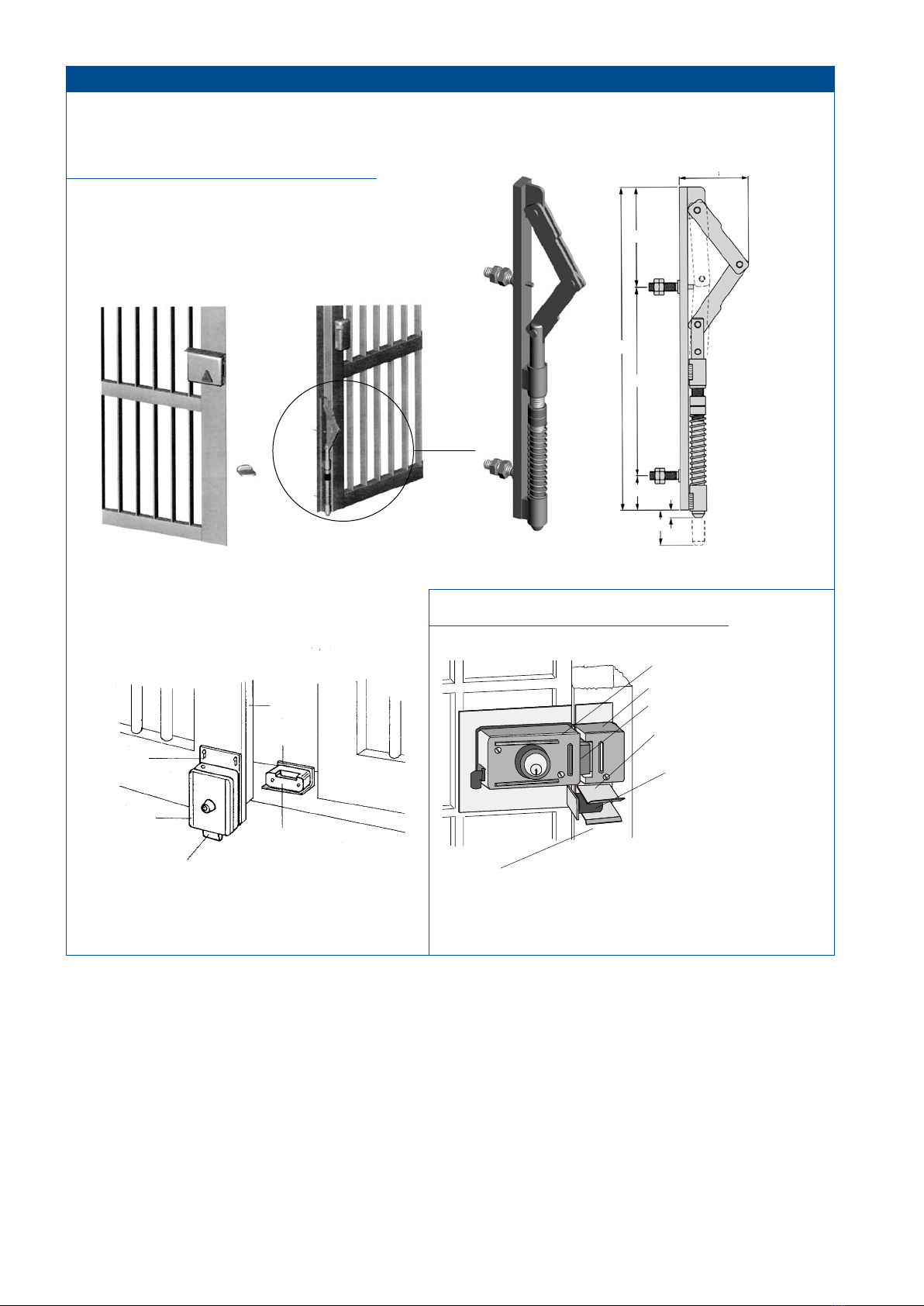
For allowing an adjustment of the e-lock (e.g. at thermal expansion of the gate) we recommend to mount the
locking plate or the e-lock on a base plate with longitudinal slots.
Mounting the e-lock on double-wing gate
• recommended way of mounting:
Lock with knee joint (optional) art. code 14560200
e-lock and locking plate are mounted at the according
gate wings (see picture)
95
306
176
35 6
30
63
• Locking with e-lock:
The locking plate is mounted at the ground (limiter).
locking plate
latch
e-lock
base plate
gate
limiter
Mounting the e-lock at single wing gate
guiding bracked
guiding roller
e-lock
locking plate
latch
• Note:
For an optimal function of the gate facility we recommend
to use a centering guide (optional) art. code 13800040
5. Mounting an e-lock (recommended for gate wings > 2,5 m) TURN 310 UF

tousek / E_TURN-310UF_43000203 / 19. 03. 2013 - 13 -

- 14 - tousek / E_TURN-310UF_43000203 / 19. 03. 2013
2x1,5 mm2
3x1,5 mm2
2
9
11
6
5
10
3 receiver
3
transmitter
10
4 receiver
4
transmitter
7
8
1
1
8
4x0,75 mm2
4x0,75 mm2
2x0,75 mm2
4x1,5
mm2
2x0,75 mm2
2x0,75 mm2
4x1,5
mm2
Note: The grounding cable has to be lead sepa-
rately from the connection box to the motor.
6. Cable plan Unterurdrehtorantrieb TURN 310 UF
Note
concerning cable laying
The electric cables have to be laid in insu-
lating sleeves which are suitable for under-
ground usage. The insulating sleeves have to
be lead into the inner of the operator housing.
230 V cables and control lines have to be
laid in separate sleeves.
Only double-insulated cables, which are
suitable for underground usage
(e.g. E-YY-J)
may be used.
In case that special regulations require
another type of cable, cables according to
these regulations have to be used.
Safety Note
Please be aware that the beside picture
is only a symbolic sample illustration of a
gate facility and may therefore not show all
safety devices required for your specic
application.
To achieve an optimum safety level at your
gate facility, please make sure that all safety
components and accessories which - ac-
cording to the applying safety rules and
laws - are required in your particular case
(e.g. photocells, induction loops, sensing
edges, signal lamps, trafc lights, mains-
and emergency power off switches etc.) are
properly installed, operated, and serviced.
In this context please follow the EU Machine
Directive, accident prevention rules and
laws, as well as applying EU- and national
standards in force at the time of installation
and operation of the gate facility.
The Tousek Ges.m.b.H. cannot be held re-
sponsible for any consequences resulting
from disregard of applying standards and
laws during installation or operation of the
gate facility.
The 0,75mm
2
control lines are shown
without ground lead. In order to facilitate
connections we recommend using exi-
ble wires and not using thicker wires for
the control lines.
1 operator Tousek TURN 310 UF
2 electronic logic control
3 external fotocell
4 internal fotocell
5 pushbutton momentary contact switch
6 radio remote receiver,
(included into the logic control box on the „ST“-models)
7 key-operated momentary contact switch
8 connection box
9 main power switch and fuse 6 A
Note: An all-pole disconnecting main switch with a contact
opening-gap of minimum 3 mm has to be foreseen
10 safety sensing edges
11 signal light

tousek / E_TURN-310UF_43000203 / 19. 03. 2013 - 15 -
Opening for inserting the
emergency release lever
415
341 ca.55
170
68
394 332
360
50
90
10
88
• dimensions in mm
7. Dimensioned drawing (left operator) Underoor operator TURN 310 UF
We reserve the right to change dimensions and
technical specifications without prior notice.

tousek PRODUCTS
• slidinggateoperators
• cantileversystems
• swinggateoperators
• garagedooroperators
• foldingdooroperators
• tracbarriers
• carparkmanagementsystem
• windowoperators
• domelightoperators
• slidingdooroperators
• electroniccontrols
• radioremotecontrols
• keyoperatedswitches
• accesscontrol
• safetydevices
• accessories
your service partner:
Tousek Ges.m.b.H. Austria
A-1230Vienna
Zetschegasse1
Tel.+43/1/6673601
Fax+43/1/6678923
Tousek GmbHGermany
D-83395Freilassing
TraunsteinerStraße12
Tel.+49/8654/7766-0
Fax+49/8654/57196
Tousek GmbHSwitzerland
CH-6275Ballwil
Bahnhofstraße14
Tel.+41/0/414482965
Fax+41/0/414482966
Tousek Sp. z o.o.Poland
PL43-190Mikołów(k/Katowic)
Gliwicka67
Tel.+48/32/7385365
Fax+48/32/7385366
Tousek s.r.o.CzechRepublic
CZ-13000Praha3
Jagellonská9
Tel.+420/2/22090980
Fax+420/2/22090989
Wereservetherighttochangedimensionsand/ortechnicalspecicationswith-
outpriornotice.Claimsresultingfrommisprintsor errorscannotbeaccepted.
tousek
E_TURN-310UF_43000203
19. 03. 2013
Table of contents
Other tousek Control Unit manuals


Popular Control Unit manuals by other brands

Amphenol
Amphenol SGX SNSORTECH PS1-O3-5-MOD Data Sheet / Manual

ViewSonic
ViewSonic VPC14-WP quick start guide

Siemens
Siemens Simatic S7-1500 manual

Siemens
Siemens SIMATIC ET 200SP HA manual

National Instruments
National Instruments 9512 C Series Getting started

Infineon
Infineon AIROC CYW20822-P4TAI040 manual


