Anritsu MA8100A TRX NEON User manual

User Guide
MA8100A
TRX NEON® Signal Mapper
You must have an Android™ smart phone or tablet and an email
address that you will use to sign in to the NEON application.
Basic familiarity with Anritsu handheld spectrum analyzers is
required.
Anritsu Company
490 Jarvis Drive
Morgan Hill, CA 95037-2809
USA
http://www.anritsu.com
Part Number: 10580-00422
Revision: E
Published: November 2020
Copyright 2020 Anritsu Company

TRADEMARK ACKNOWLEDGMENTS
LMR Master, Spectrum Master, Site Master, BTS Master, Cell Master, VNA Master, Field Master, and
Field Master Pro are trademarks of Anritsu Company.
The NEON trademark is wholly owned by TRX Systems, Inc.
The Android name and logo are property of Google LLC.
SAMSUNG is a trademark of SAMSUNG.
Windows is a registered trademark of Microsoft Corporation.
Unauthorized Use or Disclosure
Anritsu Company has prepared the product user documentation for use by Anritsu Company personnel
and customers as a guide for the proper installation, operation, and maintenance of Anritsu Company
equipment and software programs. The drawings, specifications, and information contained therein are
the property of Anritsu Company, and any unauthorized use of these drawings, specifications, and
information is prohibited; they shall not be reproduced, copied, or used in whole or in part as the basis
for manufacture or sale of the equipment or software programs without the prior written consent of
Anritsu Company.
Export Management
The Anritsu products identified herein and their respective manuals may require an Export License or
approval by the government of the product country of origin for re-export from your country. Before you
export these products or any of their manuals, please contact Anritsu Company to confirm whether or
not these items are export-controlled. When disposing of export-controlled items, the products and
manuals must be broken or shredded to such a degree that they cannot be unlawfully used for military
purposes.
Disclosure
The MA8100A TRX NEON Signal Mapper is purchased from TRX and incorporated as-is onto our
Products, and that the original and updated warning labels that TRX issues accompanying the products
still apply to them and to Anritsu as well.

MA8100A UG PN: 10580-00422 Rev. E Contents-1
Table of Contents
Chapter 1—General Information
1-1 Introduction . . . . . . . . . . . . . . . . . . . . . . . . . . . . . . . . . . . . . . . . . . . . . . . . . 1-1
1-2 Contacting Anritsu for Sales and Service . . . . . . . . . . . . . . . . . . . . . . . . . . 1-1
1-3 System Overview . . . . . . . . . . . . . . . . . . . . . . . . . . . . . . . . . . . . . . . . . . . . 1-1
NEON Signal Mapper . . . . . . . . . . . . . . . . . . . . . . . . . . . . . . . . . . . . . . 1-1
NEON Command. . . . . . . . . . . . . . . . . . . . . . . . . . . . . . . . . . . . . . . . . . 1-1
NEON Tracking Unit . . . . . . . . . . . . . . . . . . . . . . . . . . . . . . . . . . . . . . . 1-2
NEON Cloud Service. . . . . . . . . . . . . . . . . . . . . . . . . . . . . . . . . . . . . . . 1-3
Android Devices . . . . . . . . . . . . . . . . . . . . . . . . . . . . . . . . . . . . . . . . . . 1-3
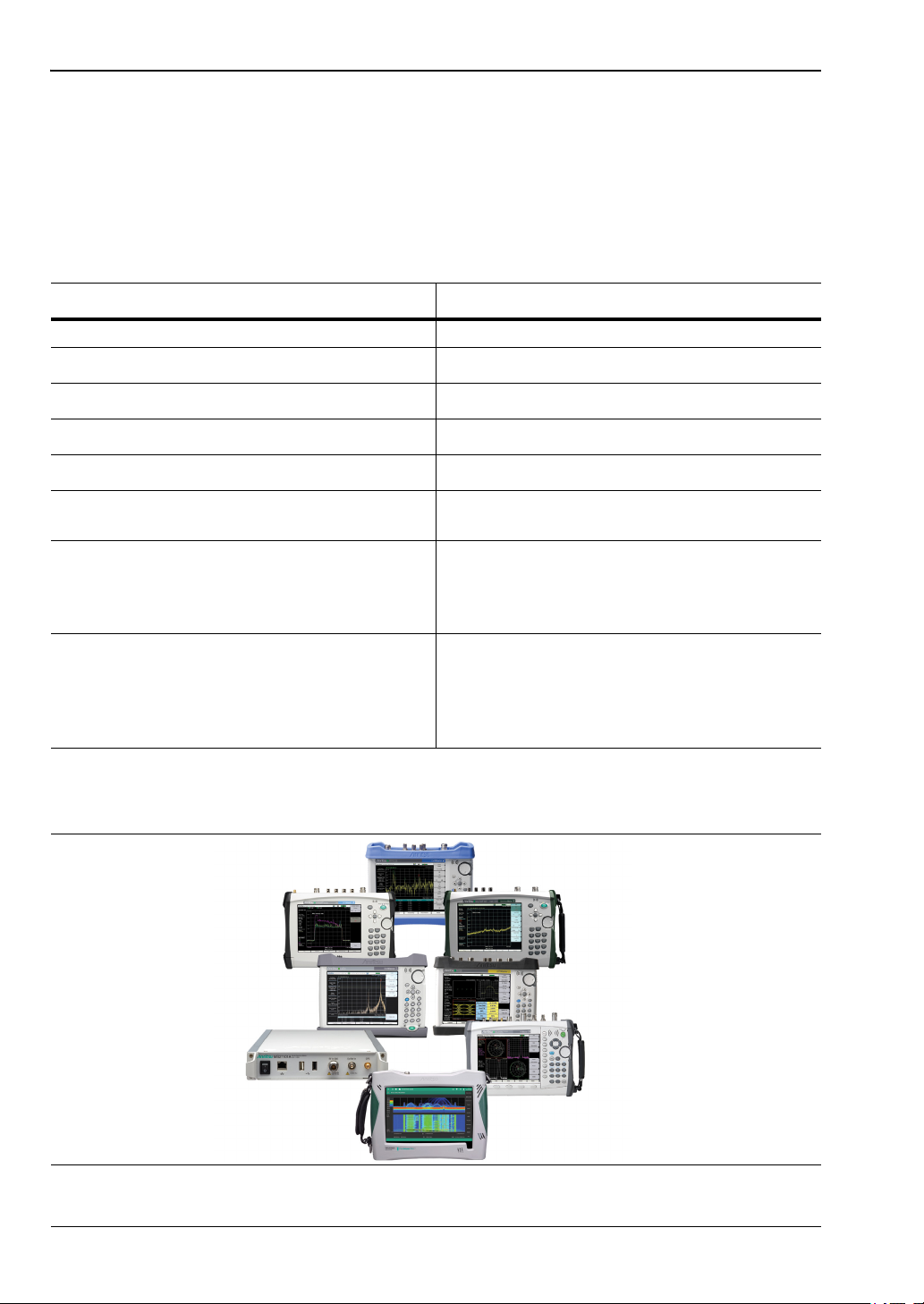
Spectrum Analyzers . . . . . . . . . . . . . . . . . . . . . . . . . . . . . . . . . . . . . . . 1-4
Chapter 2—Installing TRX NEON
2-1 Introduction . . . . . . . . . . . . . . . . . . . . . . . . . . . . . . . . . . . . . . . . . . . . . . . . . 2-1
2-2 Registration and Installation . . . . . . . . . . . . . . . . . . . . . . . . . . . . . . . . . . . . 2-1
2-3 NEON Command System Requirements . . . . . . . . . . . . . . . . . . . . . . . . . . 2-1
2-4 NEON Signal Mapper Software . . . . . . . . . . . . . . . . . . . . . . . . . . . . . . . . . 2-1
Software Update . . . . . . . . . . . . . . . . . . . . . . . . . . . . . . . . . . . . . . . . . . 2-2
2-5 Hardware Connections . . . . . . . . . . . . . . . . . . . . . . . . . . . . . . . . . . . . . . . . 2-3
Chapter 3—Site Planning
3-1 Introduction . . . . . . . . . . . . . . . . . . . . . . . . . . . . . . . . . . . . . . . . . . . . . . . . . 3-1
3-2 Log In to NEON Command. . . . . . . . . . . . . . . . . . . . . . . . . . . . . . . . . . . . . 3-1
Building Editor . . . . . . . . . . . . . . . . . . . . . . . . . . . . . . . . . . . . . . . . . . . . 3-1
Add Floors to a Building . . . . . . . . . . . . . . . . . . . . . . . . . . . . . . . . . . . . 3-1
Add a Floor Plan . . . . . . . . . . . . . . . . . . . . . . . . . . . . . . . . . . . . . . . . . . 3-2
Edit a Building in Signal Mapper . . . . . . . . . . . . . . . . . . . . . . . . . . . . . . 3-2
3-3 Offline Buildings (Optional Feature) . . . . . . . . . . . . . . . . . . . . . . . . . . . . . . 3-3
Export a Mapping Package . . . . . . . . . . . . . . . . . . . . . . . . . . . . . . . . . . 3-3
Import a Mapping Package into NEON Command . . . . . . . . . . . . . . . . 3-3
Upload a Mapping Package to Android Device . . . . . . . . . . . . . . . . . . . 3-3
Chapter 4—On-Site Mapping
4-1 Introduction . . . . . . . . . . . . . . . . . . . . . . . . . . . . . . . . . . . . . . . . . . . . . . . . . 4-1
4-2 Select the Building and Floor . . . . . . . . . . . . . . . . . . . . . . . . . . . . . . . . . . . 4-1
4-3 Pair the Tracking Unit and Android Device. . . . . . . . . . . . . . . . . . . . . . . . . 4-1
NFC Touch Pairing . . . . . . . . . . . . . . . . . . . . . . . . . . . . . . . . . . . . . . . . 4-1
Tracking Unit Selection in Signal Mapper . . . . . . . . . . . . . . . . . . . . . . . 4-2
4-4 Initialize Your Location with Signal Mapper . . . . . . . . . . . . . . . . . . . . . . . . 4-2

Contents-2 PN: 10580-00422 Rev. E MA8100A UG
Table of Contents (Continued)
4-5 Select Signal Filter Type . . . . . . . . . . . . . . . . . . . . . . . . . . . . . . . . . . . . . . . 4-2
4-6 Channel Power Measurement . . . . . . . . . . . . . . . . . . . . . . . . . . . . . . . . . . 4-3
Connect the Spectrum Analyzer to Signal Mapper . . . . . . . . . . . . . . . . 4-3
4-7 On-Site Mapping . . . . . . . . . . . . . . . . . . . . . . . . . . . . . . . . . . . . . . . . . . . . . 4-3
4-8 Signal Mapping in an Offline Building . . . . . . . . . . . . . . . . . . . . . . . . . . . . . 4-4
4-9 Signal Maps Stored on Android Device . . . . . . . . . . . . . . . . . . . . . . . . . . . 4-4
Upload Stored Signal Maps to the Cloud. . . . . . . . . . . . . . . . . . . . . . . . 4-4
Transfer Stored Signal Maps to a PC . . . . . . . . . . . . . . . . . . . . . . . . . . 4-4
Chapter 5—Signal Map Viewing and Reporting
5-1 Introduction . . . . . . . . . . . . . . . . . . . . . . . . . . . . . . . . . . . . . . . . . . . . . . . . . 5-1
5-2 Open a Signal Map Log . . . . . . . . . . . . . . . . . . . . . . . . . . . . . . . . . . . . . . . 5-1
5-3 Create a Combined Signal Map . . . . . . . . . . . . . . . . . . . . . . . . . . . . . . . . . 5-2
5-4 Generate a Heat Map . . . . . . . . . . . . . . . . . . . . . . . . . . . . . . . . . . . . . . . . . 5-2
5-5 Create Reports . . . . . . . . . . . . . . . . . . . . . . . . . . . . . . . . . . . . . . . . . . . . . . 5-3
CSV Report . . . . . . . . . . . . . . . . . . . . . . . . . . . . . . . . . . . . . . . . . . . . . . 5-4
Image Report . . . . . . . . . . . . . . . . . . . . . . . . . . . . . . . . . . . . . . . . . . . . . 5-4
iBwave Report . . . . . . . . . . . . . . . . . . . . . . . . . . . . . . . . . . . . . . . . . . . . 5-4
5-6 NEON Command Display Settings . . . . . . . . . . . . . . . . . . . . . . . . . . . . . . . 5-4
Maps Menu . . . . . . . . . . . . . . . . . . . . . . . . . . . . . . . . . . . . . . . . . . . . . . 5-4
Layers Menu . . . . . . . . . . . . . . . . . . . . . . . . . . . . . . . . . . . . . . . . . . . . . 5-5
Color Maps . . . . . . . . . . . . . . . . . . . . . . . . . . . . . . . . . . . . . . . . . . . . . . 5-5

MA8100A UG PN: 10580-00422 Rev. E 1-1
Chapter 1 — General Information
1-1 Introduction
The MA8100A TRX NEON Signal Mapper is a 3D in-building coverage mapping solution that
is integrated for use with Anritsu handheld spectrum analyzer products to automatically
collect geo-referenced test data with every step. The system allows you to perform coverage
testing of RF communications systems both indoors and outdoors. It uses inertial data from a
wearable tracking device to enable real-time 3D location and mapping inside buildings. The
system incorporates GPS data when line of sight to GPS satellites is available.
1-2 Contacting Anritsu for Sales and Service
To contact Anritsu, visit the following URL and select the services in your region:
http://www.anritsu.com/contact-us.
1-3 System Overview
The MA8100A consists of the following software and hardware.
•TRX System NEON Signal Mapper Software for Android phone or tablet
•TRX System NEON Command Software for a Windows-based PC or laptop
•TRX System NEON Tracking Unit with micro USB cable for charging the battery
•TRX System NEON Cloud Service
•Android Device
•Anritsu Spectrum Analyzer or Anritsu Remote Spectrum Monitor (User Provided)
•Android Device (User Provided)
•PC or Laptop (User Provided)
NEON Signal Mapper
The NEON Signal Mapper provides the Android user interface to test signal coverage and to
create heat maps. RF data is captured by an Anritsu Handheld Spectrum Analyzer and sent
to the Android device, typically via a USB connection. Users can edit building data, initialize
their location, start and stop the recording of signal data, and upload mapping data to the
NEON Cloud.
NEON Command
The NEON Command is a PC-based map editing and tracking software that enables the
creation and visualization of 3D building maps. It allows the user to create building outlines,
add floor plans, and generate heat maps of geo-referenced measurement results. The file
export feature lets you generate reports of the signal map data. NEON Command also
provides centralized access to the NEON Cloud Service to store and retrieve maps and
measurement data.

1-3 System Overview General Information
1-2 PN: 10580-00422 Rev. E MA8100A UG
NEON Tracking Unit
The NEON Tracking Unit shown in Figure 1-1 It is a wearable accessory that can be clasped
to a belt. The tracking unit is paired with an Android device and used to collect and process
location data. The location data is sent over Bluetooth to the NEON Signal Mapper
application running on an Android phone or tablet.
A micro USB cable is provided for recharging the NEON tracking unit battery.
LED Indicators
The NEON Tracking Unit has two LEDs to indicate device status. The top LED indicates the
accessory’s operating mode. The bottom LED indicates the charging status.
Operation LED (Top)
•Off – Tracking Unit is powered off
•Solid green – Starting up or powering down
•Blinking green – Anchor mode: device is on but not connected to the Signal Mapper app
•Blinking blue – Tracker mode, connected to NEON
•Blinking orange – Tracker mode, not connected to NEON
•Blinking purple – Bootloader starting or download in progress
•Solid purple – Bootloader Ready
•Solid green – Bootloader Success
1. Operating Mode LED
2. Power Button
3. Charge Status LED
Figure 1-1. NEON Tracking Unit
1
3
2

General Information 1-3 System Overview
MA8100A UG PN: 10580-00422 Rev. E 1-3
Charging LED (Bottom)
•Solid orange – Charging
•Solid green – Charged
•Off – USB is disconnected
•Blinking green/orange – Charging error
On/Off Procedure
Press the Tracking Unit power button to turn on the device. The top LED is solid green while
the unit is powering on. It blinks green when power-on is complete and the Tracker is not yet
connected to the Signal Mapper application (Anchor mode).
To turn off the Tracking Unit, press and hold the power button for at least a half-second. The
top LED is solid green while the unit is powering down and turns off when power down is
complete.
Calibration
The NEON Tracking Unit requires no user calibration. The magnetometer and gyroscope
within the device automatically calibrates while the user moves and stops.
NEON Cloud Service
Signal map logs containing measurement results with location information for the signals
that were detected and geo-referenced are uploaded to the NEON Cloud, where they are
accessible to users registered under the same NEON subscription.
Building data is also uploaded to the cloud when saved, except for offline buildings. Refer to
“Offline Buildings (Optional Feature)”. You can download building updates made by other
users by synchronizing NEON Command or Signal Mapper with the cloud.
Android Devices
See the suggested recommended systems requirements and Android devices at the TRX
NEON website: https://docs.trxsystems.com/signal-mapper/

1-3 System Overview General Information
1-4 PN: 10580-00422 Rev. E MA8100A UG
Spectrum Analyzers
The Anritsu’s handheld spectrum analyzer products are used with NEON MA8100A to
perform coverage mapping of RF signal data inside buildings, where GPS is not available.
The NEON MA8100A Signal Mapper is compatible with the following Anritsu handheld
models listed in Table 1-1. For information using the Anritsu handheld spectrum analyzers,
antennas, and accessories, search our product pages at https://www.anritsu.com
Figure 1-2 shows a sample of the Anritsu handheld products used with TRX NEON MA8100A
to perform coverage mapping.
Table 1-1. Compatible Spectrum Analyzers
Product family Handheld Models
BTS Master MT8220T
Cell Master MT8213E
Field Master Pro MS2090A
LMR Master S412E
Remote Spectrum Monitor MS27101A-IBCM
Site Master S332E
S362E
Spectrum Analyzers/
Spectrum Master
MS2711E
MS2712E
MS2713E
MS2720T
VNA Master
MS2034B
MS2035B
MS2036C
MS2037C
MS2038C
Figure 1-2. Handheld Spectrum Analyzers Family (User Provided)

MA8100A UG PN: 10580-00422 Rev. E 2-1
Chapter 2 — Installing TRX NEON
2-1 Introduction
In-building coverage mapping of RF data captured with an Anritsu Handheld Spectrum
Analyzer requires the use of a TRX NEON software, PC, and an Android smart phone or
tablet. The Anritsu spectrum analyzer, Android device anf PC are not included and must be
provided by the user. The TRX systems NEON Command, NEON Personnel Tracker, and
NEON Signal Mapper are downloaded from the TRX Systems website.
https://docs.trxsystems.com/
2-2 Registration and Installation
A NEON account is required to log in to the website to log in and register. To obtain details on
how to create a NEON account, go to: https://docs.trxsystems.com/subscription/
Once registered, see the NEON Signal Mapper Quick Start Guide and follow the instructions
provided: https://docs.trxsystems.com/quick-start/
The Quick Start Guide also provides instructions for:
•Site Planning
•On-Site Signal Mapping (Android)
•Generate Heat Map (PC)
•View Location Data (PC)
2-3 NEON Command System Requirements
Follow the instructions provided to register for NEON and to install the software. Review the
PC and Android requirements before installing. NEON Command is installed on a PC that
will serve as a Command Station. While NEON Signal Mapper is an Android app. the
maximum number of licensed Command Stations and Android devices depends on the
MA8100A TRX NEON Signal Mapper subscription that your company purchased.
2-4 NEON Signal Mapper Software
After registration, you will receive an email with the subject line “Welcome to NEON!”
inviting you to join your company’s NEON subscription. Click the Register for NEON button in
the email and create your login account as described in “NEON Signal Mapper Software”
on page 2-1.
Proceed with the steps below after you have registered for a login account.
1. Open a Web browser on your Android device and go to https://neon.trxsystems.com.
2. Log in to your NEON account.
3. On the Downloads page, tap the NEON Signal Mapper button.

2-4 NEON Signal Mapper Software Installing TRX NEON
2-2 PN: 10580-00422 Rev. E MA8100A UG
4. Install the Signal Mapper application by tapping the file from the drop-down
notification bar. You can also install the app from the Downloads folder on your
Android device.
Software Update
Registered users should receive an email from TRX Systems announcing a new software
version when one becomes available. Click on the included link to open the login page and you
will be directed to the NEON Downloads page.
Alternatively, you can simply open the application and a prompt will display, asking whether
you wish to update. Follow the screen prompts to update to the latest version.
With no update notification, you can still look for the latest versions of NEON Command and
NEON Signal Mapper by logging in to the Downloads page. If you already have NEON
Command open on your PC, click the Help menu and select Check for Updates. On your
Android device, tap the Signal Mapper menu button and select Check for Updates.

Installing TRX NEON 2-5 Hardware Connections
MA8100A UG PN: 10580-00422 Rev. E 2-3
2-5 Hardware Connections
The MA8100A TRX NEON Signal Mapper with spectrum analyzer is composed of the
hardware items shown in Figure 2-1. Here, an Anritsu LMR Master (S412E) is the handheld
instrument shown connected to the Android device.
Use the USB to OTG cable to connect the Anritsu spectrum analyzer to the Android device.
The Laptop or PC is used for remote monitoring and no hardware connection is required. The
NEON Tracker is a wearable remote device that has a clip that can be used to clasp onto a
user’s belt.
Refer to the In-Building Coverage Mapper Hardware Installation Guide (10580-00470) for
complete MS27101A-IBCM power-on and assembly instructions.
The NEON Tracker, Software and Android device are supplied by the user.
1. Anritsu Spectrum Analyzer (S412E)
2. Laptop or PC
3. Android Device
4. USB to OTG Cable
5. NEON Tracker
Figure 2-1. Spectrum Analyzer Setup
Note Requires an Android device and Windows PC, which are not included as part of
the mapping solution.
2
1
5
3
4

2-5 Hardware Connections Installing TRX NEON
2-4 PN: 10580-00422 Rev. E MA8100A UG

MA8100A UG PN: 10580-00422 Rev. E 3-1
Chapter 3 — Site Planning
3-1 Introduction
The primary function of NEON Command is to create building models and view tracking logs.
Adding building models allows for 3D tracking and also improves 2D tracking. This chapter
provides the basic Site Planning process. Refer to the NEON Command website and follow
the NEON Command procedures and menu interfaces to perform Site Planning.
3-2 Log In to NEON Command
Log in to the NEON Command page as described in “NEON Signal Mapper Software”
on page 2-1. The login page opens when you launch NEON Command on your PC, unless you
are already signed in. Use your registered email address and password to log in to the
application. If you are using a Gmail address, you can alternatively click on Sign in with
Google.
Building Editor
The NEON Command Building Editor features let you name a building, add floors and floor
plans, and edit the building outline and floor plans. Optionally, you can download any
building updates made by another user.
Building Editor functions are accessed and performed the same way, whether you are
entering information for a new building or modifying an existing building. If you just finished
creating a building, NEON Command automatically opens the Building Editor and displays
the Edit Building Details.
To save or discard your unsaved changes to the building data and exit the Building Editor,
click Save or Cancel, then select the appropriate response in the confirmation dialog.
The Building Editor is also available in the NEON Signal Mapper app on your Android
device.
Add Floors to a Building
After creating a building outline, you can give the building a name and set the number of
floors in the building. Perform the following steps while in Building Editor mode.
Note
Exiting NEON Command does not log you out. Next time you open the application,
you will still be logged in and the login page will be bypassed. To log out of NEON
Command, click your email address in the upper right corner of the screen and
select Logout.

3-2 Log In to NEON Command Site Planning
3-2 PN: 10580-00422 Rev. E MA8100A UG
Add a Floor Plan
You can attach a pre-existing floor plan to each floor in the building. If you don’t have the
floor plan images that you need, do an online search of floor plans for your building. .
Edit a Building in Signal Mapper
Building details and floor plans can be modified in NEON Command on a PC and in Signal
Mapper on your Android device. Signal Mapper gives you the additional ability to take and
load pictures of physical floor plans if no floor plan image files currently available.
Edit building details or change floor plans with Signal Mapper. Use fingertip motions to
resize and rotate the floor plan to make it fit over the building outline as shown in Figure 3-1.
Saved building data is automatically uploaded to the cloud and becomes available to all users
registered to the same NEON subscription. For information on how to keep building data in
local memory only and prevent it from syncing with the cloud, refer to “Offline Buildings
(Optional Feature)”.
Note
If no digital image of a floor plan exists, skip this section and use the Building
Editor on your Android device to select the Replace Floor Plan From Camera
function. This feature allows you to take pictures of a physical floor plan, such as
an emergency evacuation plan if available.
Note
When saved, the building data is normally uploaded to the NEON Cloud Service
and becomes accessible to all users registered under the same subscription.
However, if your subscription includes the option to create offline buildings,
clicking Save for the first time on a newly created building will open a prompt
asking if you want to save the building as Private (uploaded to your subscription)
or Offline (not synced with the NEON Cloud). Once a building has been flagged as
offline, subsequent saves will automatically overwrite the locally stored building
data.
Figure 3-1. Building Editor Main Screen (Android Phone)

Site Planning 3-3 Offline Buildings (Optional Feature)
MA8100A UG PN: 10580-00422 Rev. E 3-3
3-3 Offline Buildings (Optional Feature)
The optional offline building feature lets you export a building outline and associated floor
plans from NEON Command to a mapping package (.maps file) stored locally on your PC.
This building data is not uploaded to the NEON Cloud. Instead, you can upload the mapping
package later to an Android device without using the Cloud Service.
The offline building data may also be shared with users registered under the same or a
different NEON subscription by making the mapping package available to them for import
into their NEON Command application.
Export a Mapping Package
This function is available only if your NEON subscription has the optional offline building
feature enabled through TRX Systems.
Offline buildings are deleted from NEON Command when you log out of your account. To
restore the building, import the mapping package.
Import a Mapping Package into NEON Command
If an outline and floor plans already exist for your building in the form of a .maps file to which
you have access, you can load this mapping package into NEON Command instead of creating
the building from scratch.
Unlike exporting, importing mapping packages does not require the offline building option to
be enabled. This makes it easier to share building data with users under another NEON
subscription where the feature is not available.
Upload a Mapping Package to Android Device
1. Connect the Android device to your PC over USB.
2. Open the external device in Windows Explorer and create a folder named “TRXMaps”
in the top level directory.
3. Paste a copy of the mapping package (file extension .maps) into the TRXMaps folder.
4. Open the Signal Mapper app on the Android device and the offline building will load.
An “Importing Maps” message may display briefly.
Figure 3-2. TRXMaps Folder on Android Device

3-3 Offline Buildings (Optional Feature) Site Planning
3-4 PN: 10580-00422 Rev. E MA8100A UG

MA8100A UG PN: 10580-00422 Rev. E 4-1
Chapter 4 — On-Site Mapping
4-1 Introduction
NEON Signal Mapper integrates with the handheld spectrum analyzers to pull in signal data
and place it on a map. The NEON Signal Mapper app includes a visualizer that displays the
signal strength of a custom set signal on a floor plan image for real time visualization and
debugging. This chapter provides the basic On-Site Mapping process. Refer to the NEON
Signal Mapper website and follow the NEON Signal Mapper procedures and menu interfaces
to perform On-Site Mapping.
4-2 Select the Building and Floor
1. Go to the building and floor where you want to start the coverage mapping session.
2. Open Signal Mapper on the Android device and log in to your NEON account. If you
have not installed NEON Signal Mapper, refer “Registration and Installation” on
page 2-1.
3. Enter the address of the building you want to map in the input field.
4. Select the floor number from the floor selector.
4-3 Pair the Tracking Unit and Android Device
The NEON Tracking Unit is a small, wearable device that collects inertial and pressure data
used by Signal Mapper to calculate user location. It connects over Bluetooth to your Android
phone or tablet.
Before pairing the tracking unit and the Android device, turn on the tracker by pressing the
power button. The top LED blinks green (Anchor mode) when power-on is complete.
NFC Touch Pairing
Touch the TRX logo on the tracking unit to the back of the phone to pair with NFC Touch
Pairing. After pairing is successful, the top LED on the tracker will blink blue, indicating it is
on and connected to NEON (Tracker mode). If Signal Mapper is not currently open, this will
also launch the app.
For the most accurate position data, wear the unit facing front while tracking. Proceed to
“Initialize Your Location with Signal Mapper” on page 4-2.
If your Android device does not have NFC, continue with the instructions below to pair and
connect manually.
Note The tracking unit is detectable within the first two minutes of power-on. If you do
not complete the pairing in time, turn the tracker off and on, then try again.

4-4 Initialize Your Location with Signal Mapper On-Site Mapping
4-2 PN: 10580-00422 Rev. E MA8100A UG
Tracking Unit Selection in Signal Mapper
1. Start scanning for nearby Bluetooth devices.
2. Select your tracker TRX_xxxx, where xxxx is the serial number of your tracking unit,
then wait for the pairing to complete.
NEON will place the best location estimate on the screen. For accurate calculations of
heading and distance, you will need to initialize your location.
4-4 Initialize Your Location with Signal Mapper
Your location indicator in Signal Mapper consists of an error bound circle and avatar. Before
initialization, your avatar is a red dot and is likely to move in a random direction. The
location indicator is green when the tracker is initialized and locked onto your heading. The
avatar then takes the shape of an arrowhead.
1. Stand at a location that you can readily identify on the floor plan.
2. Refer to the Signal Mapper menu and click the Check-in icon.
3. Drag and reposition the map to place the green pin marker at your actual location.
4. Apply the location correction and complete the check-in. Wait for the location indicator
to reset your current position (red dot).
5. Walk straight at least 10 meters to another recognizable location.
6. Tap the Check-in icon to calibrate the heading and distance. The location indicator
turns green and the error bound circle becomes small when a good heading lock is
obtained.
Signal Mapper is now ready for tracking. To select the type of signals you want to map, go to
“Select Signal Filter Type”.
Additionally, make sure your Anritsu test instrument is connected to Signal Mapper and is
displaying measurement results before starting signal mapping.
4-5 Select Signal Filter Type
1. Refer to the Signal Mapper menu.
2. Choose Anritsu as the filter type.
3. Optionally apply a filter to the signal measurements displayed while mapping. Anritsu
LTE is currently the only filter option available for Anritsu instruments.
4. Select other optional Signal Mapper settings such as the color map applied to
measurements, the display base map, and your name and color when viewing remotely.
Note
The location indicator does not immediately follow your movement after the first
check-in. The indicator will follow your position after getting a heading lock from the
second check-in.

On-Site Mapping 4-6 Channel Power Measurement
MA8100A UG PN: 10580-00422 Rev. E 4-3
4-6 Channel Power Measurement
NEON Signal Mapper can collect channel power measurement data from all Anritsu
handheld test instruments that support Spectrum Analyzer mode. Basic familiarity with your
Anritsu test equipment is required.
Before performing in-building mapping, the spectrum analyzer must first be configured to
measure signals. Knowing the anticipated signal strength and variation, potential presence of
interfering signals, and noise sources should be used in determining analyzer settings. Refer
to the instrument user manual for detailed instructions.
Connect the Spectrum Analyzer to Signal Mapper
Attach the Android device to the spectrum analyzer using the USB OTG cable to transfer the
measurements into the NEON software as shown in Figure 2-1 on page 2-3. Alternatively, if
the device has an Ethernet connection, you can enter its IP address on the Mapper Settings
page. Refer to the Anritsu’s handheld user guide to connect to a network or directly to a PC
using Ethernet connectivity.
Connect MS27101A-IBCM to Signal Mapper
Refer to the In-Building Coverage Mapper Hardware Quick Start Guide (10580-00470) for
complete MS27101A-IBCM power-on and assembly instructions.
4-7 On-Site Mapping
1. Tap the blue button to start Mapper mode. NEON will automatically detect and
geo-reference sensors and signals as you move.
2. Walk through areas where you want to collect RF signal data. Signal strength is
represented by a colored dot. A gray dot means no signal is detected at that location.
A timer is displayed on the screen while you are mapping. The latest signal reading is
shown, updating every second. Also displayed are the signal type being tracked, the
building floor, and bars indicating the strength of the heading lock.
3. Display all signals of the selected type that have been scanned in the last 15 seconds.
4. Optionally, change the signal type to change the type of signals displayed.
5. Stop recording signal data.
6. In the Mapping Finished dialog, enter a name for the log file, then upload map.
The uploaded signal map can later be opened in the NEON Command application on
your PC.
Other choices in the Mapping Finished dialog let you discard the map or continue mapping.
Storing the map locally will create the signal map in the Android device’s local folder.
Note
If your location indicator becomes inaccurate, the phone will vibrate and Signal
Mapper will stop collecting signal map data. If this happens, check-in at multiple
locations until your avatar turns green. The app will then resume signal mapping.

4-8 Signal Mapping in an Offline Building On-Site Mapping
4-4 PN: 10580-00422 Rev. E MA8100A UG
4-8 Signal Mapping in an Offline Building
This topic applies only to buildings flagged as offline when they were created and saved in
NEON Command. Offline building data is not uploaded to the cloud and is available in the
form of a mapping package only to users who have access to this file. Refer to “Offline
Buildings (Optional Feature)” for more information.
All the tasks related to conducting an on-site signal mapping session in a private building, as
described in the previous sections, apply to an offline building. The only difference is in saving
the mapping data locally on the Android device instead of uploading it to the cloud.
When you are done collecting signal map data, tap the red button to stop recording. In the
Mapping Finished dialog, enter a name for the log file. The signal map is saved to the phone's
memory in the folder NeonSignalMaps.
4-9 Signal Maps Stored on Android Device
Signal maps that are saved locally on an Android device are stored in a folder named
NeonSignalMaps. From here, the signal maps can be uploaded to the cloud at any time.
Additionally, you can manually transfer map data collected in an offline building from the
Android device to your PC without using the NEON Cloud Service.
Upload Stored Signal Maps to the Cloud
1. Upload Signal Maps from the Signal Mapper menu.
2. Find the desired signal map log and select it, then Upload Selected.
3. Open the signal map in NEON Command.
Transfer Stored Signal Maps to a PC
1. Connect the Android device to your PC over USB.
2. Open the external device in Windows Explorer and open the folder named
“NeonSignalMaps.”
3. Copy the signal map file (extension .sigmap) to the appropriate location on your PC.
4. Open the signal map in NEON Command.
Table of contents
Popular Data Logger manuals by other brands

Extech Instruments
Extech Instruments 382100 user manual

Instrumentation Northwes
Instrumentation Northwes AquiStar PT2X instruction manual

YOKOGAWA
YOKOGAWA Datum Y XL100 user manual

Omega
Omega OM-21A instruction sheet

NexSens Technology
NexSens Technology CB-40 user guide

NexSens
NexSens X2-Cell quick start