manuals.online logo
Brands
  1. Home
  2. •
  3. Brands
  4. •
  5. Antec
  6. •
  7. Enclosure
  8. •
  9. Antec NINE HUNDRED TWO V3 User's User manual

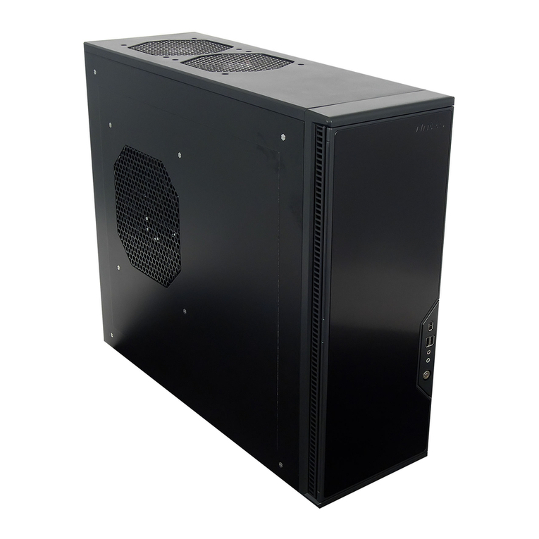
Antec NINE HUNDRED TWO V3 User's User manual

Other Antec Enclosure manuals

Antec Sonata Designer 500 User manual

Antec

Antec Sonata Designer 500 User manual

Antec SONATA III 500 User manual

Antec

Antec SONATA III 500 User manual

Antec P193 User manual

Antec

Antec P193 User manual

Antec Fusion Remote Max User manual

Antec

Antec Fusion Remote Max User manual

Antec Veris Fusion Remote Max Quick start guide

Antec

Antec Veris Fusion Remote Max Quick start guide

Antec Solution SLK3700AMB User’s User manual

Antec

Antec Solution SLK3700AMB User’s User manual

Antec NAK3480 User manual

Antec

Antec NAK3480 User manual

Antec SLK3800B User manual

Antec

Antec SLK3800B User manual

Antec Minuet User manual

Antec

Antec Minuet User manual

Antec Dark Fleet DF-35 User manual

Antec

Antec Dark Fleet DF-35 User manual

Antec Performance TX635 User manual

Antec

Antec Performance TX635 User manual

Antec OVERTURE II User manual

Antec

Antec OVERTURE II User manual

Antec Mini P180 White User manual

Antec

Antec Mini P180 White User manual

Antec Dark fleet DF-10 User manual

Antec

Antec Dark fleet DF-10 User manual

Antec Nine Hundred Two User manual

Antec

Antec Nine Hundred Two User manual

Antec SOLO UCC 13# 0761345-08500-7 EU User manual

Antec

Antec SOLO UCC 13# 0761345-08500-7 EU User manual

Antec P190 User manual

Antec

Antec P190 User manual

Antec Twelve Hundred User manual

Antec

Antec Twelve Hundred User manual

Antec ISK 300-65 User manual

Antec

Antec ISK 300-65 User manual

Antec Super LANBOY User manual

Antec

Antec Super LANBOY User manual

Antec P280 User manual

Antec

Antec P280 User manual

Antec Veris Fusion 430 User guide

Antec

Antec Veris Fusion 430 User guide

Antec Fusion Remote Max User manual

Antec

Antec Fusion Remote Max User manual

Antec ISK 100 User's User manual

Antec

Antec ISK 100 User's User manual

Popular Enclosure manuals by other brands

ENERMAX iVektor.Q ECA 3371 Series user manual

ENERMAX

ENERMAX iVektor.Q ECA 3371 Series user manual

Lindy 43095 user manual

Lindy

Lindy 43095 user manual

SICK C4000 Select operating instructions

SICK

SICK C4000 Select operating instructions

Geeek A60 PLUS installation guide

Geeek

Geeek A60 PLUS installation guide

OVE SYDNEY 48 installation manual

OVE

OVE SYDNEY 48 installation manual

SilentiumPC Armis AR5 Hardware installation

SilentiumPC

SilentiumPC Armis AR5 Hardware installation

Pulsar 17/TRP80/DSPR Assembly instructions

Pulsar

Pulsar 17/TRP80/DSPR Assembly instructions

MSI MPG SEKIRA 500X quick start guide

MSI

MSI MPG SEKIRA 500X quick start guide

Peavey DS 1502 Specifications

Peavey

Peavey DS 1502 Specifications

D-Link ShareCenter Pro DNS-1550-04 user manual

D-Link

D-Link ShareCenter Pro DNS-1550-04 user manual

Rosewill RX82-U(JBOD) user manual

Rosewill

Rosewill RX82-U(JBOD) user manual

QNAP SAS JBOD CLI 1.0 user guide

QNAP

QNAP SAS JBOD CLI 1.0 user guide

GAMDIAS Talos P1 Quick installation guide

GAMDIAS

GAMDIAS Talos P1 Quick installation guide

Auvs KR615 user manual

Auvs

Auvs KR615 user manual

CommScope FDH 3000 user manual

CommScope

CommScope FDH 3000 user manual

FS FHD-FWME4 quick start guide

FS

FS FHD-FWME4 quick start guide

JBL CS1215T owner's manual

JBL

JBL CS1215T owner's manual

Pulsar ARAD-S4 manual

Pulsar

Pulsar ARAD-S4 manual

manuals.online logo
manuals.online logoBrands
  • About & Mission
  • Contact us
  • Privacy Policy
  • Terms and Conditions

Copyright 2025 Manuals.Online. All Rights Reserved.

NINE HUNDRED TWO V3
U
SER
’
S
M
ANUAL
1
Table of Contents
Introduction
1.1 Case Spe ifi ations ............................................................................................. 3
1.2 Diagram .............................................................................................................. 3
Hardware Installation Guide
2.1 Setting Up .......................................................................................................... 4
2.2 Power Supply Installation .................................................................................. 4
2.3 Motherboard Installation..………………………………………………… ............................ 4
2.4 Flexi-Drive Bay System………….………………………………………… ............................... 5
2.5 Internal 3.5” Devi e Installation…………………………………………. ........................... 5
2.6 External 3.5” Devi e Installation………………………………………… ............................ 6
2.7 External 5.25” Devi e Installation………………………………………. ........................... 6
2.8 Internal 2.5” Devi e Installation…………………………………………. ........................... 7
2.9 Cable Management Compartment……………………………..………............................ 7
2.10 Water Cooling Platform…………………………………………………… .............................. 8
2.11 Three-Way SLI Configuration Option…………………………………… .......................... 8
Connecting the Front I/O Ports
3.1 USB 2.0 Ports………………………………………………….…………… .................................. 8
3.2 USB 3.0 Port…………………………………….………………………….. .................................. 8
3.3 AC’97 / HD Audio Ports……………………….…………………………. ................................ 9
3.4 Power Swit h / Reset Swit h / Hard Disk Drive LED Conne tors…. ................... 9
3.5 Rewiring Motherboard Header Conne tions…………………………… ...................... 10
Cooling System
4.1 Big Boy 200 mm TriCool™ Fan………………………………………….. ............................. 10
4.2 Front/Rear TriCool™ LED Fans …………………………………………. ............................. 11
4.3 Optional Fans.………………………………………………………………. ................................. 12
4.4 Washable Air Filters………………………………………..……………… ............................... 13
2
Congratulations on your pur hase of the Nine Hundred Two V3!
The best-selling Ante Nine Hundred offers gamers an unbeatable en losure, one that delivers a
ombination of ooling, performan e and onvenien e and stands head and shoulders above the
ompetition. The Nine Hundred Two V3 builds on this design, adding a CPU utout, internal bottom-
mounted 2.5” SSD drive bay and front USB 3.0 port. We know your gaming hardware produ es a lot of
heat, so we’ve built this ase for maximum ooling, with a perforated front bezel, three 120 mm fans
with mounts for even more fans and a monster top-mounted 200 mm fan.
The Nine Hundred Two V3 omes without a power supply. Make sure you hoose a power supply that is
ompatible with your omputer omponents and has a long enough power harness to rea h your
motherboard and peripheral devi es. We re ommend our High Current Gamer or High Current Pro
power supplies for the latest ATX spe ifi ation omplian e, broad ompatibility, and power-saving
apability.
At Ante , we ontinually refine and improve our produ ts to ensure the highest quality. It’s possible
that your new ase will differ slightly from the des riptions in this manual. This isn’t a problem; it’s
simply an improvement. As of the date of publi ation, all features, des riptions, and illustrations in this
manual are orre t.
Disclaimer: This manual is not designed to over CPU, RAM, or expansion ard installation. Please
onsult the motherboard manual for spe ifi mounting instru tions and troubleshooting. Before
pro eeding, he k the manual for your CPU ooler to find out if there are steps you must take before
installing the motherboard. While installing hardware, keep your ase on a flat, stable surfa e.
3
1.1 Case S ecifications
Case Type
Mid Tower
Color
Bla k
Dimensions
19.3” (H) x 8.7” (W) x 18.5” (D)
493 mm (H) x 218 mm (W) x 472 mm (D)
Weight
25.4 lbs / 11.5 kg
Cooling
1 x Top
200 mm
TriCool™ Blue LED 3
-
speed Fan
2 x Front 120 mm Blue LED Fan with Front Control Knobs
1 x Rear 120 mm TriCool™ Blue LED 3-speed Fan
1 x Side 120 mm Fan Mount (Optional)
1 x Middle 120 mm Fan Mount (Optional)
Drive Bays
10
Drive Bays:
-Up to 9 x External 5.25” Drive Bays
-Up to 6 x Internal 3.5” Drive Bays
-1 x External 3.5” Drive Bay Bra ket (Optional)
-1 Internal bottom-mounted 2.5” SSD drive
Expansion Slots 8 expansion slots to support three-way SLI onfiguration
Motherboard Size
Mini-ITX, mi roATX, Standard ATX
Front I/O Panel
2 x USB 2.0
1 x USB 3.0
AC’97/HD Audio In and Out
1.2 Diagram
1. 120 mm rear TriCool™ fan
2. 200 mm top TriCool™ fan
3. 2 front 120 mm fans with
front ontrol knobs
4. 1 middle 120 mm fan bra ket
5. Washable air filters
6. Motherboard mount
– Mini-ITX, mi roATX or
Standard ATX
7. CPU utout
8. Power supply mount
9. 9 total 5.25” drive bays
10. Re onfigurable 3.5” drive
ages
11. Internal 2.5” SSD drive bay
12. Front I/O panel
13. 8 expansion slots (Three-way SLI apable)
1
2
3
7
9/10
8
12
4
5
6
13
11
4
Hardware Installation Guide
2.1 Setting U
1. Pla e the ase upright on a flat, stable surfa e so that the rear panel (power supply and expansion
slots) is fa ing you.
2. Remove the panel thumbs rews from the side panel and open it by sliding it towards you.
Note: Pla e the panel thumbs rews arefully aside as they are NOT inter hangeable with the HDD
age thumbs rews.
3. Remove the panel thumbs rews from the other side panel and open it by sliding it towards you.
Pla e the s rews arefully aside. Inside the ase is the power supply mount at the lower rear of the
ase and the 5.25” drive bay area with two HDD ages inside the bays. You will also find some wiring
with marked onne tors (USB, PWR et .), an installed I/O panel and a toolbox ontaining more
hardware (s rews, brass standoffs, et .).
Note: Don’t use your fingernails to pry or lift the panels.
2.2 Power Su ly Installation
1. With the ase upright, pla e the power supply on
the four sili one pads on the bottom of the ase.
Note: Power supplies will need to be mounted
so that the PSU fan is fa ing the top of the ase.
Nine Hundred Two V3 provides mounting holes for
power supplies with standard mounting layouts
to be installed upside up or upside down.
2. Push the power supply to the ba k of the ase and
align the mounting holes.
3. Atta h the power supply to the ase with the s rews
provided.
2.3 Motherboard Installation
1. Lay the ase down so that the open side is up.
2. Make sure you have the appropriate I/O panel
for the motherboard. If the panel provided is not
suitable for the motherboard, please onta t
the motherboard manufa turer for the orre t
I/O panel.
3. Line up the motherboard with the standoff
holes. Determine whi h holes line up and
remember where they are. Not all motherboards
will mat h with all of the provided s rew holes,
and this is not ne essary for proper
fun tionality. Some standoffs may be pre-
installed for your onvenien e.
5
4. Lift up and remove the motherboard.
5. S rew in the brass standoffs to the threaded
holes that line up with the motherboard.
6. Pla e the motherboard on the brass standoffs.
S rew in the motherboard to the standoffs with
the provided Phillips-head s rews.
2.4 Flexi-Drive Bay System
The Nine Hundred Two V3 omes with nine 5.25” external drive bays at the front of the ase. There are
three HDD ages pre-installed inside the bottom six 5.25” bays. Ea h HDD age o upies three
onse utive 5.25” drive bays and an house three hard disk drives. For maximum flexibility you an
mount the HDD age anywhere within the external drive bays (i.e., you are not limited to the bottom six
bays).
Possible drive bay ombinations in lude but are not limited to:
• External 3 x 5.25” + internal 6 x HDD
• External 6 x 5.25” + internal 3 x HDD
• External 9 x 5.25”
There is a middle fan bra ket pre-installed on one of the HDD ages. You an install a 120 mm fan to the
bra ket so the air will be blown into the ase to use the HDD age as a ooling du t to ool your graphi s
ard or CPU. This will prevent the installation of hard drives into this age, however. Remove the middle
fan bra ket from the HDD age if you de ide to mount your hard drives into this age.
• External 3 x 5.25” + internal 3 x HDD + ooling du t
2.5 Internal 3.5” Device Installation
1. Remove both side panels per the instru tions in Setting Up.
2. Remove the age thumbs rews fastening the HDD age to
the frame.
3. Slide the HDD age forward out of the front of the ase.
4. Mount the hard drive in the drive age and fasten it using
the long s rews provided.
5. Slide the HDD age ba k into the ase and fasten it with
thumbs rews.
6. Conne t the appropriate onne tor(s) from the power supply
to the devi e(s). Leave some sla k in the onne tions so that
you an easily a ess the fan filters for leaning.
6
7. There is a 120 mm fan pre-installed into ea h age. Conne t
the 4-pin onne tor to the power supply.
Note: There is a middle fan bra ket pre-installed on one of
the HDD ages. Remove it from the age if you de ide to
mount your hard drives into this age.
2.6 External 3.5” Device Installation
1. Remove both side panels per the instru tions
in Setting Up.
2. Remove the drive bay over from the drive bay
you wish to install an external 3.5” drive into.
3. Install your external 3.5” devi e into the adapter.
4. Slide the drive adapter/devi e assembly into the bay.
5. S rew the adapter to the drive age.
6. Mount the fa eplate and se ure it with s rews.
2.7 External 5.25” Device Installation
Note: The HDD ages ea h o upy three onse utive
drive bays, and will blo k installation of larger devi es
su h as opti al drives, so please plan ahead before
installing your drives.
1. Remove both side panels per the instru tions in
Setting Up.
2. Remove the s rews fastening the appropriate metal
drive bay over(s) to the sides of the ase.
3. Remove the over(s).
4. If ne essary, please remove the HDD age that is
pre-installed in the bay.
5. Slide the 5.25” devi e into the bay from the front of
the ase.
6. Fasten the drive using the s rews that ame with your
drive.
7. Conne t the appropriate power and interfa e onne tors
from the power supply and motherboard to the devi e.
Make sure that you leave some sla k in the onne tions
so that you an easily a ess the fan filters for leaning.
8. Mount the other devi es a ordingly.
7
2.8 Internal 2.5” Device Installation
At the bottom of your ase, there are mounting holes designed to support one 2.5” SSD devi e.
1. Lo ate the plasti bag labeled “For 2.5 HDD” and
remove the 4 sili one grommets.
2. Install the grommets into the four holes at the
base of the ase at the bottom of the drive bay
area as shown. You should install them with the
thi k part of the grommets fa ing the inside of
the ase.
3. Lay the Nine Hundred Two V3 on its side, and
hold the drive in pla e on top of the grommets.
4. Se ure the devi e to the ase with the s rews
provided, tightening the s rews with your fingers
first, and then the s rewdriver.
5. Conne t the appropriate power and data ables
to your devi e
2.9 Cable Management Com artment
There is a able management ompartment between the motherboard and right side panel. You an
tu k or route ex ess ables in this ompartment.
1. Remove both side panels.
2. Choose the ables you would like to pass through the holes behind the motherboard tray and pull
them out of the power supply hamber towards the right side of the ase.
3. Use the able ties provided to hold them in pla e.
4. Feed the ables ba k through the insertion point nearest the destination of the able. Conne t the
able and then pull the sla k ba k to the right side of the ase.
8
Pin
Signal
Names
Pin
Signal
Names
1
USB
Power
1
2
USB
Power
2
3
Negative
Signal
1
4
Negative
Signal
2
5
Positive
Signal
1
6
Positive
Signal
2
7
Ground
1
8
Ground
2
9
Key
(No
Connection)
10
Empty
Pin
2.10 Water Cooling Platform
This ase omes with a 5.25” metal plate pre-installed in the 3rd 5.25” drive bay. This plate is designed
to allow you to easily mount omponents of a water- ooling kit su h as a pump or reservoir. The plate
an be mounted in any of the nine 5.25” drive bays for maximum flexibility.
Note: The plate is not pre-drilled. You will need to drill the appropriate holes to be ompatible with
your water- ooling kit.
2.11 Three-Way SLI Configuration O tion
The Nine Hundred Two V3 has eight expansion slots, making it apable of supporting up to three
graphi s ards in triple-SLI onfiguration. Consult your motherboard and graphi s ards manuals for
more information.
Conne ting the Front I/O Ports
3.1 USB 2.0
Conne t the front I/O panel USB able to the USB header pin on your motherboard. Che k the
motherboard manual to ensure that it mat hes the table below:
3.2 USB 3.0
There is a pre-routed able for the front-panel USB 3.0 port. Plug the ba k end of this able into an on-
board USB 3.0 port on your motherboard to enable the front USB 3.0 port.
1 2
9 10
9
Pin
Signal
Names
(HDA)
Pin
Signal
Names
(AC’97)
1
MIC2
L
1
MIC In
2
AGND
2
GND
3
MIC2
R
3
MIC Power
4
AVCC
4
N
C
5
FRO-R
5
Line
Out
(R)
6
MIC2_JD
6
Line
Out
(R)
7
F_IO_SEN
7
N
C
8
Key (no pin)
8
Key (no pin)
9
FRO-L
9
Line
Out
(L)
10
LINE2_JD
10
Line
Out
(L)
3.3 AC’97/HD Audio Ports
There is an Intel® standard 10-pin AC’97 onne tor and an Intel® 10-pin HDA (High Definition Audio)
onne tor linked to the front panel of the ase.
You an onne t either the AC’97 or the HDA onne tor, depending on the model of the motherboard.
Lo ate the internal audio onne tors from your motherboard or sound ard and onne t the
orresponding audio able. Consult your motherboard or sound ard manual for the pin-out positions.
Even if your system supports both audio standards, you may only use one onne tor.
3.4 Power Switch / Reset Switch / Hard Disk Drive LED Connectors
Conne ted to your front panel are LED and swit h leads for power,
reset, and HDD LED a tivity. Atta h these to the orresponding
onne tors on your motherboard. Consult your motherboard
manual for spe ifi pin header lo ations. For LEDs, olored wires
are positive ( + ). White or bla k wires are negative ( – ). If the LED
does not light up when the system is powered on, try reversing the
onne tion. For more information on onne ting LEDs to your
motherboard, see your motherboard manual.
Note: Polarity (positive and negative) does not matter for swit hes. There is also no Power LED in this
ase. The illuminated ase fans will turn on when there is power to the omputer.