Antennas4Less SignaLoop HF-319 User manual

SignaLoopTM
Portable HF Magnetic Loop
Antenna System
Model HF-319
Contents:
Introduction............................................................... 2
Safety information..................................................... 3
Warranty information................................................. 4
Assembling and using your antenna.......................... 5
Illustrations................................................................. 6
Usage Hints................................................................. 7
**IMPORTANT NOTE: LOOPCONNECTORS MUST BE CLEANAND TIGHTATALL
TIMES DURING OPERATION. PROPERANTENNA FUNCTION ABSOLUTELY
DEPENDS ON IT! **
For questions, please feel free to visit us on the web at http://www.antennas4less.com and use the
-----------------
*Please note: specified frequency coverage & performance is available ONLY if the supplied tuning
unit is used along with the supplied coaxial loop cable. Use of the tuning unit with any other length
and/or type of cable may result in somewhat unpredictable frequency coverage and/or performance and
is not endorsed.
1

Introduction
Thank you for purchasing the SignaLoop Portable HF Magnetic Loop Antenna System from
Antennas4Less. These antennas are ideal for most any application where a very small, often
unobtrusive yet high performance HF antenna is needed –i.e. apartments, hotels/motels, temporary
demonstrations, camping/hiking, and any other space constricted area. Many operators are using small
magnetic loop antennas with good performance results in communities where larger antennas are
restricted or not permitted. This antenna is ideal forAmateur Radio, Emergency Communications,
Short Wave Listening, and many other applications. Small HF loop antennas have long been utilized
anywhere in which very compact size along with high performance are needed.
Main Features:
Ultra portable. Can be easily stored inside a small case, bag, backpack, etc.
Very lightweight. 1.5lbs.(0.7kg.) without included PVC stand, 3lbs.(1.36kg) with stand.
A great HF antenna solution for Hiking, SOTA, EMCOMM, etc.
Built-in standard tripod mount for use with photo tripods if needed.
Common SO239 connection to radio.
No separate coupling loop needed. Tuning and coupling components are housed within a single
enclosure.
Very quick and easy to tune as needed. Simply tune for maximum noise on receive and then apply
transmit power & fine tune (if needed) for lowest SWR.
Transmit/Receive frequency coverage is continuous from 3 mhz to 19 mhz, including the 80/75m,
60m, 40m, 30m, 20m and 17m Amateur Radio bands.
Design provides good performance at all covered frequencies.
Rated transmit power of 20 watts* P.E.P. SSB/CW, 10 watts* continuous carrier.(*For 80/60/40m - 12w
PEP/10w continuous.)
Does not require any type of counterpoise, ground radials, nor ground connection for operation.
Does not require an antenna tuner. Tuner is built-in.
Inherent low-noise, high signal ratio.
Hi-Q design helps to reject off-channel interference.
Directional & magnetic signal response properties of the antenna allow for high rejection of local
noise sources along with maximum reception of the desired signal.
2

SAFETY INFORMATION
WARNING: INSTALLATION OF THIS PRODUCT NEAR POWER LINES IS DANGEROUS! FOR YOUR SAFETY, FOLLOW
THE PROVIDED INSTALLATION INSTRUCTIONS. INSTALLER ASSUMES ALL LIABILITY FOR PROPERTY AND LIFE
SAFETY.
WARNING: HIGH VOLTAGES MAY BE PRESENT ON THE LOOP ANTENNA ELEMENT AND ASSOCIATED
CONNECTORS DURING TRANSMITTER OPERATION. DO NOT TOUCH ANY PART OF THE ACTUAL LOOP ANTENNA
ELEMENT OR CONNECTORS WHILE TRANSMITTING!
EXCESS RF EXPOSURE WARNING
In the United States, the Federal Communications Commission has established guidelines for human exposure
to Radio Frequency (RF) electromagnetic fields. The commission's requirements are detailed in parts 1 & 2 of
the FCC's rules and regulations [47 CFR, 1.1307(b), 1.1310, 2.1091, 2.1093]. It is the responsibility of the
owner/operator of this device to follow all applicable warnings and precautions regarding human
exposure to RF fields.
The FCC Office of Engineering Technology (OET) Bulletin 65, Supplement B, Evaluating Compliance
with FCC Guidelines for Human Exposure to Radio frequency Electromagnetic Fields directly
concerns the use and operation of the model HF-319 Portable Magnetic Loop Antenna System. This
bulletin establishes safe operating distances from the loop antenna and associated power levels in order
to permit the operator and persons who may be impacted by operation to exist in a safe environment.
Guidelines for Maximum Permissible Exposure or MPE are defined in Supplement B of the bulletin.
IMPORTANT NOTE:
Refer to the above mentioned Supplement B along with FCC OET Bulletin 65, Version 97-01. The
information in the supplement provides additional details which are used for evaluating compliance of
amateur radio stations with FCC guidelines for exposure to radio frequency electromagnetic fields.
However, Supplement B users should also consult Bulletin 65 for complete information on FCC
policies, guidelines and compliance-related issues. Definitions of terms used in this supplement appear
in Bulletin 65. Bulletin 65 can be viewed and downloaded from the FCC’s Office of Engineering and
Technology’s World Wide Web Internet Site:
http://www.fcc.gov/oet/rfsafety
3

WARRANTY INFORMATION
LIMITED PRODUCT WARRANTY
Antennas4Less warrants its products to be free from defects in material and workmanship for a period of one
hundred eighty (180) days from date of shipment. Any product found to be defective within this time period
may be returned to our factory, freight prepaid, with prior return authorization for repair or replacement (at
our discretion) at no charge (with the exception of batteries and other expendable items). Our liability under
this warranty is limited to the repair or replacement of the defective product and in no event shall
Antennas4Less be liable for consequential or indirect damages to goods, property, equipment or personnel. Nor
shall we be liable for damages to equipment or for personal injury caused by misuse, overload, accidental
damage, alteration, improper installation, or unauthorized opening of the equipment. Under no circumstances
will we be responsible for any indirect or consequential damages due to errors in or failure of our product to
perform properly.
LEGAL DISCLAIMER NOTICE
Specifications of the products discussed and/or displayed herein are subject to change without notice.
Antennas4Less or anyone on its behalf, assumes no responsibility or liability for any errors or inaccuracies.
Information contained herein is intended to provide a product description only. No license, express or implied,
by estoppel or otherwise, to any intellectual property rights is granted by this document. Except as provided in
our terms and conditions of sale for such products, we assume no liability whatsoever, and disclaim any express
or implied warranty, relating to sale and/or use of our products including liability or warranties relating to
fitness for a particular purpose, merchantability, or infringement of any patent, copyright, or other intellectual
property right. The products shown herein are not designed for use in medical, life-saving, or life-sustaining
applications. Customers using these products in such applications do so at their own risk and agree to fully
indemnify us for any damages resulting from such improper use or sale. Risk of loss of the products shall pass to
the buyer when the products are tendered by us for shipment to the buyer. THIS WARRANTY CONSTITUTES OUR
EXCLUSIVE WARRANTY. THERE ARE NO OTHER WARRANTIES, EXPRESS OR IMPLIED, INCLUDING ANY WARRANTY
OF MERCHANTABILITY OR FITNESS FOR A PARTICULAR PURPOSE.
4

Assembling and using your antenna
Assembly:
The SignaLoop model HF-319 loop antenna is designed to be ultra portable and is very quick & easy to
deploy. The antenna can be used either with or without the included support which is constructed
from 1/2-inch schedule 40 PVC pipe. The PVC sections are cleaned using Acetone before shipping so
that they may be painted by the user if desired. The HF-319 can be mounted to a photo tripod if
desired, and a standard 1/4x20 female thread mount is located inside the bottom of the PVC antenna
support for this purpose.
In some cases such as long-range hiking, mountain climbing, etc. it may be desirable to take along only
the coaxial loop element and the tuning/coupling unit so as to minimize weight. This way weight of
the antenna system is just 1.5lbs.(0.7kg.). In these situations, the PVC loop support can be left behind
and the loop may be supported simply by hanging from convenient natural objects such as trees, tall
bushes, large rocks, etc.
In other cases such as camping, hotel/motel room use, use in apartments, ham radio demonstrations,
or any other place where a very compact yet high performance HF antenna is needed, use of the
antenna with the provided PVC support may be best.
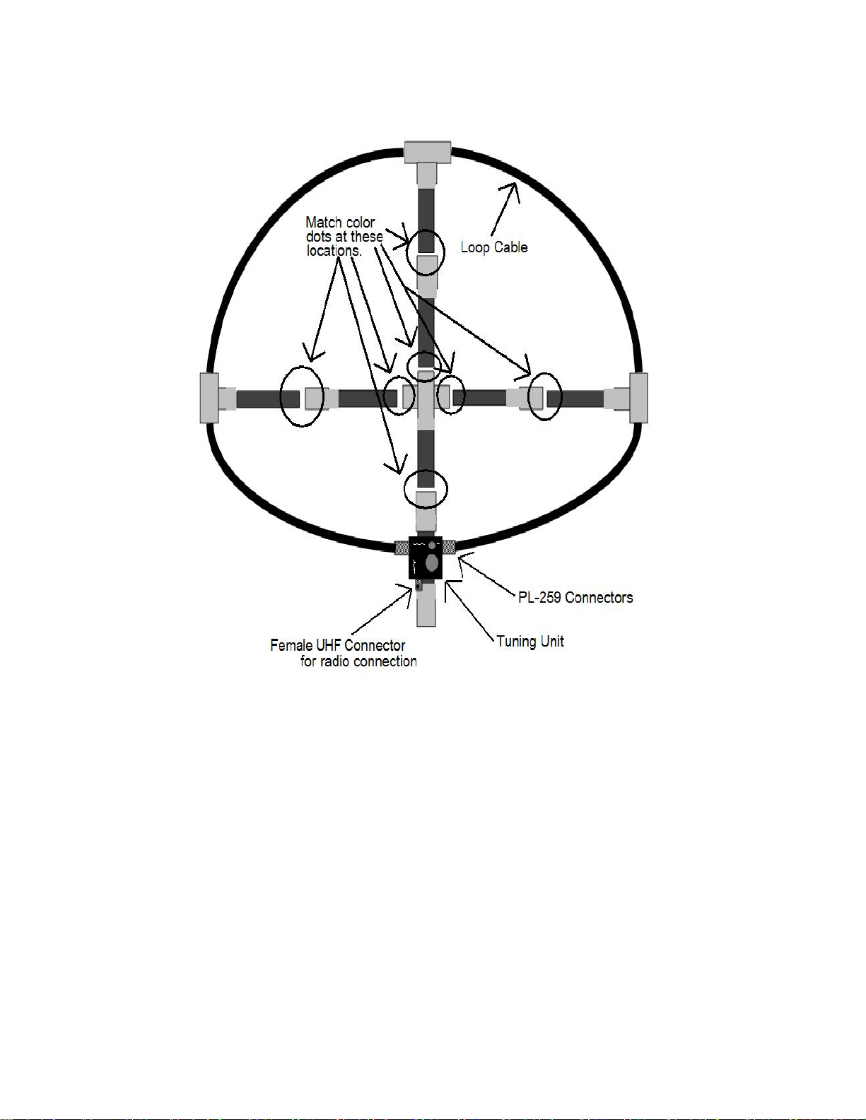
Assembly of the antenna is very simple and involves these steps:
(Refer to figs. 1 & 2 on the following pages for illustration of assembly)
(If not using the included antenna support then uncoil loop coax and proceed to step 3)
1) Assemble the antenna support if you are going to use it. (refer to fig. 2 on page 6).
2) Uncoil the coaxial loop element and thread cable through the “Tee” connectors at the ends of
the PVC support arms.
3) Connect the male connectors at each end of the loop coax to the corresponding female
connectors (Marked “LOOP”) on the tuning unit. IMPORTANT: For proper operation, the loop
connectors must be clean and tight at all times during antenna operation.
4) Connect an appropriate cable between the “RADIO” connector on the bottom of the tuning unit
and your radio. The antenna is now ready for use.
Initial Tuning
Tuning the loop antenna is very simple. First, select the frequency on which you wish to operate.
Second, adjust the “Tuning” control on the loop tuning unit for maximum background noise level on
receive. If you only wish to receive (i.e. SWL), then no other steps are needed. For transmit operation,
one additional step is needed: Key the transmitter on CW/AM/FM or any continuous carrier mode,
using about 5-8 watts of power. Readjust the “Tuning” control on the loop tuning unit for minimum
SWR If an SWR indicator is available. See Page 8 for further discussion regarding transmit tuning.
5

To assemble PVC Antenna Support, simply line up & match the color dots which are found at mating
joints on the stand. Connect the pieces together by lining up the color dots and simply push the smaller
pipes into the larger couplings.
6

A few usage hints
Small loop antennas such as this one usually show a bi-directional radiation pattern –i.e. a figure-
eight pattern with deep nulls which are perpendicular to the plane of the antenna, and maximum
signal strength within the loop plane. Also, in the near field, these antennas respond primarily to the
magnetic component of a given signal rather than the electrical component. These things can be
advantageous in several ways. For receiving, the antenna can be rotated either for maximum signal
strength or for minimum background noise. Rotating the antenna for minimum background noise will
usually result in the best signal-to-noise ratio and often will cause signals to “rise up” out of the noise,
even though the desired signal may be lower in strength on the S-meter as compared to pointing the
antenna directly at the signal or compared to a larger antenna such as a dipole. After tuning the HF-
319 loop antenna on a given frequency, both ways of rotation should be tried and then using that
which results in best reception of the desired signal. In other words, strongest signal and best
reception may not necessarily be the same, especially in areas with high levels of man-made RF noise.
Nulls of the HF-319 antenna are quite sharp so be sure to rotate the antenna slowly while listening for
best reception. If you intend to transmit to a specific station, it might be best to rotate the loop for
maximum receive signal strength from that station before transmitting.
Transmit Tuning:
USE NO MORE THAN 10-12 Watts of transmit power during tuning.
Note that tuning for lowest SWR during transmit may be somewhat “touchy”, especially on higher
frequencies such as 20m & 17m. This is true for all loop antennas of this type. After a bit of practice it
becomes quick & easy. Using a technique called “Reverse Tuning” seems to work well. i.e.- With TX
keyed, SLOWLY turn the tuning knob on the tuning unit until a dip in SWR is observed. Pull hand away
from the tuning box and note the SWR reading at that point. Grasp the tuning knob again and gently
turn it counterclockwise until SWR reading matches that which was just noted after moving the hand
away from the tuning box. At this point, when the hand is once again moved away from the tuning
control, TX SWR should then be at its lowest point.
** Note: When tuning frequencies within the 60m (5mhz) Ham band, use the "3-5" mhz setting of the
range switch on the tuning unit. Correct tuning will occur near the extreme clockwise position of the
tuning control. **
Note also that lowest SWR does not always reflect best transmit efficiency, and that in most cases it is
much better to simply tune for maximum transmitted radiation by using a field-strength meter or
other such indicating device placed within 6-18 inches of the loop coaxial cable. Then simply key the
TX and tune for maximum indication on the field-strength device.
7
Table of contents