Naval PR-422CA User manual

7
70
02
28
8
W
We
es
st
t
W
Wa
at
te
er
rs
s
A
AV
VE
E,
,
S
Su
ui
it
te
e#
#3
39
93
3,
,
T
Ta
am
mp
pa
a,
,
F
FL
L
3
33
36
63
34
4-
-2
22
29
92
2,
,
P
Ph
h:
:
(
(8
81
13
3)
)
8
88
85
5-
-6
60
09
91
1,
,
F
Fa
ax
x:
:
(
(8
81
13
3)
)
8
88
85
5-
-3
36
60
01
1
E
Em
ma
ai
il
l:
:
s
sa
al
le
es
s@
@n
na
av
va
al
l.
.c
co
om
m,
,
W
We
eb
bs
si
it
te
e:
:
w
ww
ww
w.
.n
na
av
va
al
l.
.c
co
om
m
Operation Manual
Video Entertainment System
PR-422CA Marine AM-FM/TV Antenna
PR-420CA Marine FM/TV Antenna
NSN: 5985-01-369-2757 PN: PR-420CA (0GMC3)
NSN: 5985-01-379-9838 PN: PR-422CA (0GMC3)
Printed in USA

P
PR
R-
-4
42
22
2C
CA
A
M
Ma
ar
ri
in
ne
e
A
AM
M/
/F
FM
M/
/T
TV
V
A
An
nt
te
en
nn
na
a
f
fo
or
r
S
Sh
hi
ip
ps
s
P
P
R
R
-
-4
42
20
0C
C
A
A
M
Ma
ar
ri
in
ne
e
F
FM
M-
-T
TV
V
A
A
n
nt
te
en
nn
na
a
f
fo
or
r
S
Sh
hi
i
p
p
s
s
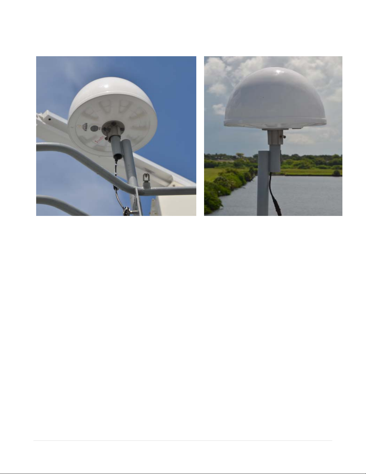
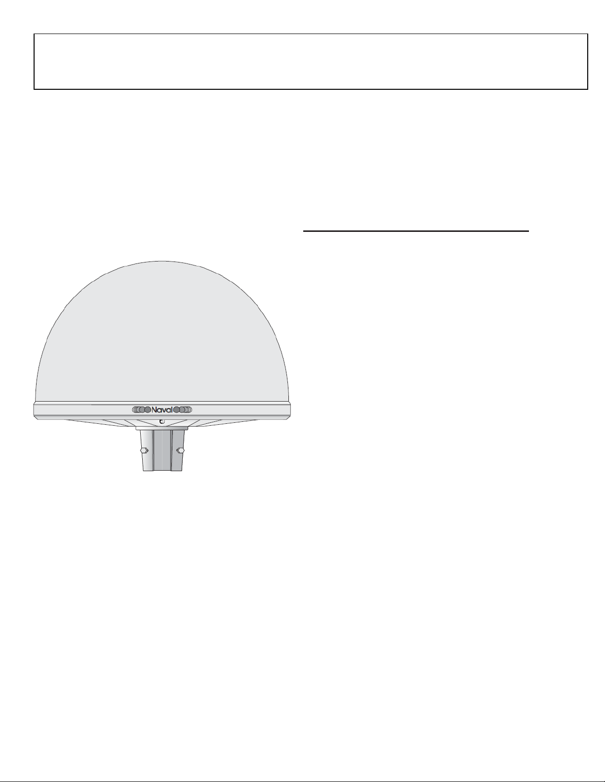
The PR-422CA is an Active Extra High Performance Omni-directional wide-band Terrestrial AM-FM-
TV Antenna ( 0.1-30 and 40-860 MHz) designed for Maritime purposes where second rate efficiency
is unacceptable. Constructed for High End Commercial and Military use, this compact and robust
antenna shell is made of thick UV protected ABS plastic filled with polyurethane foam which
provides both structural support and environmental protection. The mounting base is cast from
Almag Marine Aluminum Alloy which is powder coated and then oven baked. Mounting hardware is
made of acid-proof stainless steel. The Shielded Low Noise Amplifier is protected from static
charges and is removable for field repair or replacement.
Specifications: PR-422CA antenna
Frequency range: PR-422 (0.1-860 MHz), PR-420 (40-860 MHz)
Average VHF gain: 25 dB (amp)
Average UHF gain: tilt 16-20 dB (amp)
VHF Noise figure: 3.0 dB (amp)
UHF Noise figure: 2.5 dB (amp)
Max output level: 111 dBuV min (2 signals-60 dBIM)
Third order intermod products: >20dB IP3
Antenna factor: Ka = 0.12 AM
Filters: Band pass 100 KHz- 30 MHz., 47-108 MHz.,
174-230 MHz.,470-860 MHz.
Broadband rejection filter: 140-165 MHz.
Polarization: horizontal
Antenna pattern: omni-directional
Supply voltage to antenna: 15VDC nominal
Current consumption: 130 mA Nominal
Operating temperature: -40 to +55 C.
Protection circuits: static discharge device fires at 65 volts
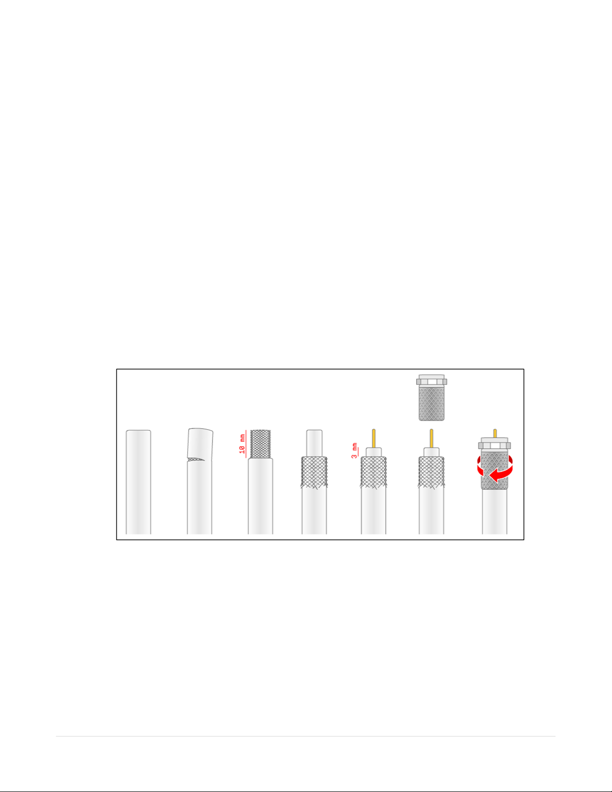
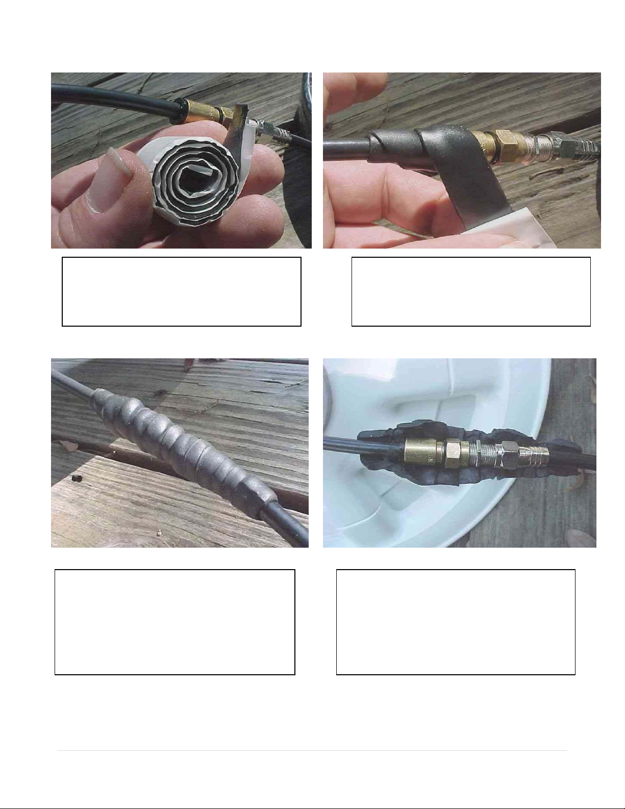
Impedance: 75 ohm nominal
Connector "F" type Gold electroplate or BNC-75
Return loss: >10dB with optional output connector.
Radome material: UV protected ABS
Flange material: Stainless, Almag or Powder Coated Almag
Internal stabilization material: Polyurethane foam injection
Element material: copper foil
Element type: three looped dipoles with Z match pcb
Shipping Weight: 12-13 lbs with 1 ft coax and aluminum flange
Shipping container dim : 19 x 19 x 16 inches
The PR-422CA is based on a construction of 3 circular dipoles coupled to a low noise amplifier via a
broadband filter network. Maximum performance is assured through the extensive use of a Network
Analyzer in the initial design and in the final construction and tuning of each unit. Microwave
transistors provide needed gain with a minimum of internally generated noise. Careful engineering
and the use of very high quality components yields excellent intermod performance and sharp hand
tuned filters greatly reduce the chance of interference from outside of the TV bands
The PR-422CA is at the head of a new 4000 Series Marine Cassette Amplifier System with
distribution passives introduced in 1998. The Series 4000 is the result of painstaking engineering
and the use of state of the art components such as high performance GaAs Heterojunction Bipolar
Transistors.
PR- 420CA is identical with the omission of AM-SW radio rece
p
tion.

1 | 9
Naval PR-422CA is an Active Extra High Performance Omni-directional wide-band active Terrestrial
AM-FM-TV Antenna (0.1-30 and 40-860 MHz)) for Maritime purposes where second-rate efficiency
is unacceptable. It covers AM-SW and FM Radio bands as well as TV bands.
Naval PR-420CA is an Active Extra High Performance Omni-directional wide-band active Terrestrial
FM-TV Antenna (40-860 MHz) for Maritime purposes where second-rate efficiency is unacceptable.
Constructed for High End Commercial and Military use, this compact and robust antenna shell is
made of thick UV protected ABS plastic filled with polyurethane foam which provides both structural
support and environmental protection. The mounting base is cast from Almag Marine Alloy. Almag 35
is a high purity alloy of aluminum and magnesium. Mounting hardware is made of stainless acid-proof
steel. All Almag/stainless interfaces are protected with TefGel to prevent electrolysis and galling. The
Shielded 3-band Low Noise Amplifier is protected from static charges and is removable for field repair
or replacement. Projected life at sea >15 years.
This internal amplifiers receive (+15VDC) operating power from the Naval head-end via coax cable. It
is removable, through the mounting flange, for repair or upgrade. This is a factory repair item and
should not be serviced by the untrained.
This antenna is based on a construction of 3 circular dipoles coupled to a low noise amplifier via a
broadband filter network. Maximum performance is assured through the extensive use of a Network
Analyzer in the initial design and in the final construction and tuning of each unit.
Microwave transistors provide needed gain with a minimum of internally generated noise. Careful
engineering and the use of very high quality components yield excellent inter-mod performance and
sharp hand tuned filters greatly reduce the chance of interference from outside of the TV bands.
The PR-422CA/PR-4420CA is at the head of the 4000 Series Marine Cassette Banded Amplifier
System with distribution passives introduced in 1998. The Series 4000 is the result of painstaking
engineering and the use of state of the art components such as high performance GaAs
Hetrerojunction Bipolar Transistors.

2 | 9
Installation Instructions for: TV Antenna System.
Mount the PR-422CA/PR-420CA antenna high on the ship’s superstructure, clear of nearby objects. It
is best if the antenna is the highest object on the ship to insure maximum possible range and Omni-
directional performance. Do not mount the antenna in the beam of radar.
Mount the antenna on a 2-inch pipe that is braced against resonant vibrations. The antenna has a
short coaxial lead ending in an F connector. Make a barrel connector splice to RG-11 coaxial
cable; seal the splice and connectors against moisture and water entry, using “coax-seal” or similar
waterproof putty. The usual precautions should be taken in installing the coaxial cable run. Clamp it
against downloading force, so that the connection will not pull apart from the weight of the cable. Take
care not to crush the cable, and avoid bends over sharp edges. The coaxial run to the head end
amplifier should be less than 75 feet for best results. Any coaxial cable exposed to sunlight should be
painted with non-metallic paint to prevent possible UV damage over the long term.
Bolt the head end amplifier to the bulkhead in a position convenient for service, preferably at a height
corresponding to eye level for a standing person. Be sure to allow room to open the cabinet door.
Connect the Cabinet Ground to Ship’s Ground.
A direct AC supply to the PRA-420 (Power Supply and Line Amplifier for FM-TV) or PRA-422 (Power
Supply and Line Amplifier for AM-FM-TV) should have a circuit breaker or switch, or alternatively
should be supplied at an AC outlet in the same room. The room should be dry, with ventilation for heat
to escape. A TV set should be in sight of the head end amplifier so as to help when performing
adjustments to the system. It is often convenient to use a small portable TV set for this purpose. A
20dB test point is provided on the PR-4900 (Output Filter) to connect the monitor TV. Do not use any
of the 4 (-8dB) ports as the levels there are too high for the monitor and will cause overloading.

3 | 9
The head end amplifier cabinet is supplied with feed-through F connectors. The shipyard may wish to
change over from RG-11 cable to RG-6 with a pigtail splice near the cabinet; alternatively, RG-11 may
be connected direct to the F connectors on the cabinet if convenient.
All coaxial cables should be tagged on each end with a non-metallic tag. The tag ID should be
indicated on as-fitted drawings.
Outlets are supplied with plastic ground isolation bases. These reduce possible problems with ground
loops aboard a steel ship. When making connections to these “passives”, the connector may be
slightly wrench-torqued so as to insure a lasting connection throughout the life of the ship.
Water resistant F-connectors with Silicone gel sealant and O rings are available on request for RG-6
and RG-59 cables, but are not yet available for RG-11. A good quality connector should be selected
(such as Amphenol), as well as a quality crimping tool. It is important for the installer to be properly
skilled in making these connections. RG-11 is best for the branch runs from the head end to the first
passive connection; RG-6 can be used after that, providing the runs are not excessive in length. Keep
in mind that coax-cable losses affect the UHF frequencies much more than the lower VHF frequencies
so it is possible to lose the upper UHF channels altogether if the coax length and losses are
excessive.
Testing:
Equipment Required:
-TDR (Time Domain Reflectometer): Tektronics or equivalent.
- Frequency Selective Voltmeter: SENCOR or equivalent
Test procedures:
TDR reading should be taken on each piece of coaxial cable where physical measurements are not
possible. Lengths of all cables (to one foot accuracy) should be shown on as-fitted drawings. In
addition to determining cable lengths, the TDR is able to see anomalies on the coax, and the installer
should use this feature to insure that the cables and connections are true.
Perform a system test after installation is completed, before closing ceiling panels, etc. Inject a pilot
signal at the head end. For this purpose, a VCR generates a good signal and is convenient to use as
a pilot signal generator, as it is a repeatable signal source for future troubleshooting.
Experiences have shown that Shore Cable signals can vary from hour to hour and as such should not
be used to inventory system levels. Most VCR units usually have a switch to allow RF output on either
channel 2 or 3. Use either channel for the test; note the channel chosen on the as-fitted drawings.
When used with PRA-422/PRA-420 Power Supply-Amplifier, Attenuators: Each attenuator is a 3 turn
potentiometer and is rather delicate. Use a tuning tool or small screwdriver. Turn slowly so the end of
travel stop may be felt..
Inject the VCR signal to the selected input port on the PRA-422/PR-420. While viewing the
appropriate channel on the TV monitor, reduce attenuation on the amplifier until some signal
degradation is noticed; then increase attenuation until this degradation is reduced. The amplifier is
now adjusted for maximum gain without overdriving it. (The attenuator is situated at the amplifier
input) Note the level of this Pilot. This level should be recorded and will be the reference point for all
further tests.

4 | 9
Levels can now be taken at each coaxial output connector throughout the system, ie., at the end of
each cable and at the output of each passive (splitter/tap-off/outlet). These levels must be recorded
on a system block diagram or sketch. Levels can be referenced to either one microvolt or one millivolt,
whichever is more convenient. There is 60 dB difference between the dBuV and dBmV figures; all
drawings should indicate which reference is used. It is strongly recommended that readings be made
using a logarithmic dB scale, since confusion often arises when linear voltage readings are used.
When testing is complete, the cable and connector attenuation values should correspond to the
various signal level readings taken throughout the system. If a part of the system has higher than
calculated attenuation, the problem must be investigated and corrected. When this happens, levels
downstream from the correction point must be taken again, and recorded on the as-fitted drawings.
These final drawings are invaluable for future trouble shooting. Copies should be made for Naval
Tampa, the Ship-owner, and the Shipyard for future reference. Naval Tampa will archive such
drawings in hard copy and on electronic media where possible.
Typical problems:
Improper terminations: These will show up as a higher-than-calculated loss; they can be frequency
sensitive. They may also show as a short or open circuit if the termination is seriously corrupt.
Proper installer skills, hardware and tools are essential to a good working system. Factory Engineers
are available at reasonable cost to travel worldwide.
Stripping of coaxial cable for supplied twist on connectors.
Final Adjustments:
Before commencing any testing, ensure that the system is powered up and that the amplifier is active.
See the note on “Attenuators” in the Test Procedures section, above.
It is, of course, better to use testing and measuring equipment when available, such as a signal
generator and a frequency-selective voltmeter.
If no measuring equipment is available: Connect the antenna to the PR-4010 (Input and power). Use
a TV monitor attached to the 20dB test point on the PR-4900 (Output filter).

5 | 9
Locate a TV station in the low VHF band and adjust the monitor for best picture. Locate the attenuator
on the PR-422CA/PR-420CA and turn it full counter clockwise to introduce maximum attenuation of
20 dB. Turn the attenuator slowly clockwise while observing the monitor.
At some point some signal degradation may be noticed as the amplifier starts to over-drive.
At this point the attenuation should be increased again slightly CCW to limit over driving. The amp is
now at maximum gain without overdrive.
Using a Signal Generator and Frequency Selective Voltmeter: For the channel under adjustment,
disconnect the antenna or other input device. Feed the generator to the Antenna Input port via a DC
block. Adjust the level of the generator for 0 dBmV and a frequency suitable for the amplifier being
adjusted. Measure the signal at the outlet with the weakest signal (typically at the end of the longest
or highest loaded branch. Using the corresponding attenuator, adjust so as to obtain a level of max
0dBmV at this outlet. Repeat the above procedure for each amplifier in the system.
When replacing the older MK-20CA antenna you will need a BNC to F connector which we supply free
of charge with a splice kit, when requested.
Technical Specifications
Frequency range: PR-422CA AM-FM-TV Antenna: 1.0-30MHz and 40-860 MHz
PR-420CA FM-TV Antenna: 40-860 MHz
Gain: 14-25 dB
Noise factor: 4.5 dB Max.
Output level: 111 dBuV (2 signals-50 dBIM)
Supply voltage: 15 V DC
Current consumption: approx. 130 mA
CE Mark designed tested and certified.

6 | 9
Using Coax-Seal® to waterproof a coax cable splice
This is a new space age plastic material which will quickly and effectively seal all types of coax cable
fittings. COAX-SEAL stays flexible for years thus insuring moisture proof connections, good SWR and
long coax-cable life. Make sure fittings and coax cable are clean and dry before applying. Peel six
inches of COAX-SEAL and wrap around by winding from coax cover toward fitting with one half
overlap with each winding.
Shown below is a short pigtail of RG-59U coax cable terminated in a Snap and Seal "F" connector
which is then joined to a female-female adapter or barrel connector. The antenna shown is an Active
Marine TV Antenna as used by the US Navy.
The next few photos will show how this barrel connector is used in a splice and how it is waterproofed
for marine use.
The second cable with connector is
attached to the barrel adapter and
wrench torqued. The connector on the
right has an O ring in it's mouth and it
is sealed to the coax internally with
silicone grease.
This shows the cable from the
amplifier to the barrel connector.

7 | 9
A small roll of Coax-Seal. It is a putty like
material in tape form. The white waxed paper
keeps it from sticking to its self.
Note that the first wrap comes back on itself
exactly and the second turn starts the diagonal
wrap. Wrap from the coax cover toward the
fitting with one half overlap with each winding.
The last wrap again comes straight back over the
previous wrap without a diagonal. The seal is
slightly sticky and should be molded now by hand
to remove any gaps and to ensure that all the
wraps are blending together. At some point the
wraps will almost fuse together and the material
may have to be cut away from the cable.
A view of the connectors with the coax seal cut
away from the connectors

8 | 9
Most common problems with this antenna:
1. Water entry into the F connections just below the antenna...electrolysis will corrode the soft copper
center conductor of the coax.
Cure: Clean off the corrosion, dry the connectors and seal against the weather with "coax-seal" putty
tape. Electrical tape will not ensure a water tight connection.
2. Separation of the coax from the internal amplifier's printed circuit board from not supporting a long
cable against downloading or, from a sharp pull to the coax.
Changeable Antenna Amplifier
Reference from www.naval.com/tube-amp
Removing the changeable/repairable amplifier
Look into the mounting flange and the white plastic cap will be seen. Grip the rim of the cap with long
nose pliers and pull. Move pliers to the other side of the cap and pull and wiggle. The cap should
break free of its silicone rubber seal and slide towards you on the cable with the black rubber boot
attached. This will expose the snap ring retainer. Using a snap ring tool, compress the snap ring and
remove it. The amplifier can then be removed by a steady pull on the coax cable. It is connected to
the inside of the antenna simply by a push on PAL connector as shown above.
Once the amplifier has been removed, push the coax cable into the tube and the whole assembly will
slide out the top of the tube.

9 | 9
FOOTNOTE: This product is normally produced as RoHS but can be modified with leaded solder to
increase reliability under extreme shock, temperature (thermal fatigue), and vibration at sea. Lead
content is then less than 10 grams of Lead (Pb) total. Specify with order and note that RoHS
certification and sticker are omitted. The product has an expected life of 15+ years at sea through
experience since initial production. The leaded PCB is easily removed and can be shipped to the
manufacturer for proper disposal as needed at no charge, at end of life.
This manual suits for next models
1
Table of contents
Other Naval Antenna manuals
Popular Antenna manuals by other brands

Kathrein
Kathrein BZD 40 manual

TERK Technologies
TERK Technologies XM5 owner's manual

ETS-Lindgren
ETS-Lindgren 3167 user manual

LF Engineering
LF Engineering H-800 SKYMATCH quick start guide

CUSHCRAFT
CUSHCRAFT MA8040V Assembly and installation instructions

Radio Shack
Radio Shack OPTIMUS 15-1843 instructions