4
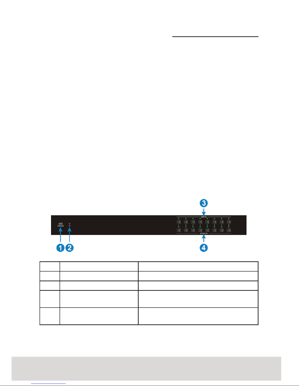
No. Name Description
4 IR OUT • 8 x IR OUT: Plug in IR emitters to
deliver the IR signal sent from the far-
end receivers connected to the HD-
BaseT ports. These IR OUT sockets
make up an IR matrix with the IR IN
sockets on the far-end receivers, and
all can be switched simultaneously
with the AV signal, or separately from
switching. In default setting, the 1~7
IR OUT corresponds with the 1~7 IR
IN, i.e. IR OUT1 - IR IN1, IR OUT2 -
IR IN2, …IR OUT7 - IR IN7.
• 1 x IR ALL OUT: Plug in IR emitter to
deliver the IR signal to control input
source device form any of far-end
receivers.
5 CONTROL • RS232: Serial port for unit control,
3-pin pluggable terminal block, con-
nects with control device (e.g. PC).
• TCP/IP: RJ45 port. Connect with PC
for Web-based GUI control.
6 AUDIO OUTPUTS • SPDIF: Digital audio output connects
directly via an optic bre cable to the
Toslink input on a sound bar.
• RCA (L&R): PCM Analogue audio out-
put sockets connect the de-embedded
audio additional speakers.
7 AC100V~240V • Power port, connect with power cord
Note: Pictures shown in this manual are for reference only, different model and speci-
cations are subject to real product.