5
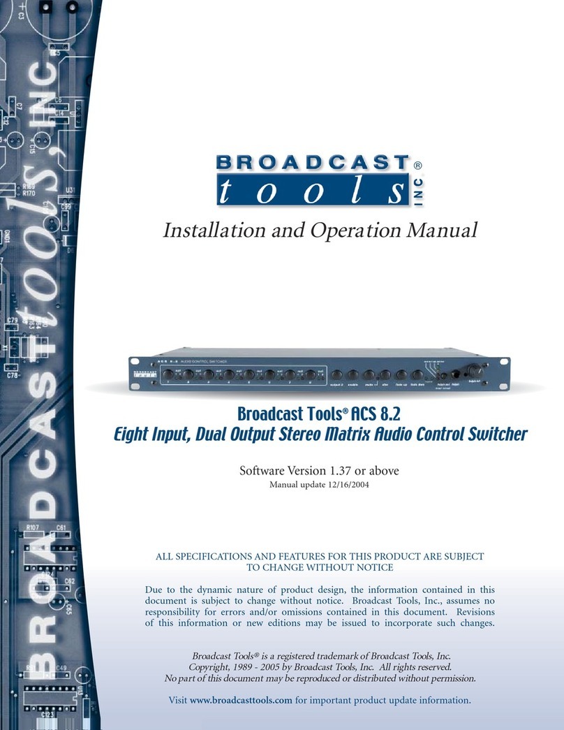
SS 8.2 Installation and Operation Manual
DESCRIPTION
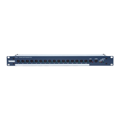
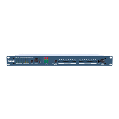
Controls:
• Output monitoring switch for the dot graph VU meters, headphone and powered
speaker amplifiers.
• Headphone jack.
• Headphone level control.
• Powered speaker level control. This line level output may be muted.
Audio Inputs:
Each of the 8 stereo inputs are balanced bridging (20KΩ) at a nominal line level of
+4dBv. Sufficient gain is provided for unbalanced consumer level products. Multi-
turn level controls are provided for each channel. Solder pads are provided for ter-
minating resistor, if needed.
Audio Outputs:
The SS 8.2 provides two selectable balanced stereo outputs. Two balanced monaural
outputs are also provided which follow their respective stereo outputs. The output
“0” VU level is set at +4dBm @ 47 Ωand may be adjusted from off to + 24 dBm.
Silence Sensor:
The SS 8.2 contains individual silence sensors, which may be configured to moni-
tor either of the two stereo output channels. For each channel, a peak-detect circuit
drives A/D converters on the microprocessor. The factory default delay is set at 10
seconds, with a threshold of 20 dB below program and may be set via a NON-ded-
icated computer. Upon silence detection, the “Silence Sensor” SPDT relay is closed
for the duration of the silence, and the corresponding (L or R) LED is lit for the dura-
tion of the silence. The sensor may be programmed for:
• Number of seconds of silence that must be present before an alarm state is
reached or terminated.
• Level to be considered silence. This is achieved by feeding a stereo audio tone
or program material to the desired threshold of silence and then entering a menu
or burst command.
PIP Input:
The Parallel Input Port with the Programmable Pulse Stretcher provides 16 pulse-
stretched parallel 5 volt TTL/CMOS compatible inputs. The inputs are pulled high
to 5 volts through a 10KΩresistor and are activated by pulling the input to ground.
These inputs supply status to any serial polling device (when the unit ID is set to 0,
no polling of inputs is required). For each channel, a pulse of specified minimum
input duration (000 to 2.55 seconds) causes the status to go true until the longer of
the minimum specified length (0.000 - 9.99 seconds) or the end of the input pulse.
The pulse width may vary between the specified value and 10 ms less than that
value. This allows the polling computer more time to detect an input change.
WEBSITE:
Visit our web site for
product updates and
additional information
