Antona ANC-6023 User manual

1
Rev A
User’s Manual
ANC-6023
RS232/RS422/Video Sync Interface Adapter

2
Copyright
Copyright © 2006-2015 by Antona Corporation. All rights reserved. No part of this publication may be
transmitted, transcribed, stored in a retrieval system, or translated into any language or computer language,
in any form or by any means, electronic, mechanical, magnetic, optical, chemical, manual or otherwise,
without the prior written permission of the Antona Corporation of Los Angeles, California.
Warranty
Antona Corporation products are warranted to be free from defects in materials and workmanship for a
period of one (1) year from the date of original shipment to customer. This warranty is limited to the
replacement or repair of parts not subjected to misuse, neglect, unauthorized repair, alteration (except card
options), accident, or failure due to the effects of static electricity discharge.
In no event shall Antona Corporation be liable to the purchaser for loss of use, profit, or consequential
damages, or damages of any kind, including, but not limited to, accidental loss or damage to other
equipment, arising out of use of Antona Corporation equipment, whether or not said equipment was used
properly. The designer is responsible for the determining the suitability and use of the product.
This warranty is in lieu of any other warranty, expressed, implied, or statutory, including, without
limitation, any implied warranty or merchantibility or fitness for a particular purpose. No amendment of
this warranty may be effected except in writing by an officer of the Antona Corporation.
Warranty Repairs
All repair services shall be performed at the Antona Corporation plant in Los Angeles, Ca. THE
PURCHASER MUST OBTAIN A RETURN AUTHORIZATION FROM THE ANTONA
CORPORATION PRIOR TO RETURNING ANY PIECE OF EQUIPMENT. Shipment to the
Antona Corporation will be at the expense of the purchaser, return shipment will be at the expense of the
Antona Corporation for all repairs.

3
2
Table of Contents
User’s Manual................................................................................................................. 1
ANC-6023........................................................................................................................... 1
RS232/RS422/Video Sync Interface Adapter................................................................. 1
Copyright.................................................................................................................... 2
Warranty ..................................................................................................................... 2
Warranty Repairs........................................................................................................ 2
Table of Contents............................................................................................................ 3
Features........................................................................................................................... 4
Overview......................................................................................................................... 4
Mechanical Specifications.............................................................................................. 4
Adapter case size: ....................................................................................................... 4
Connectors:................................................................................................................. 4
Electrical Specifications ................................................................................................. 5
ANC-6023 Installation.................................................................................................... 5
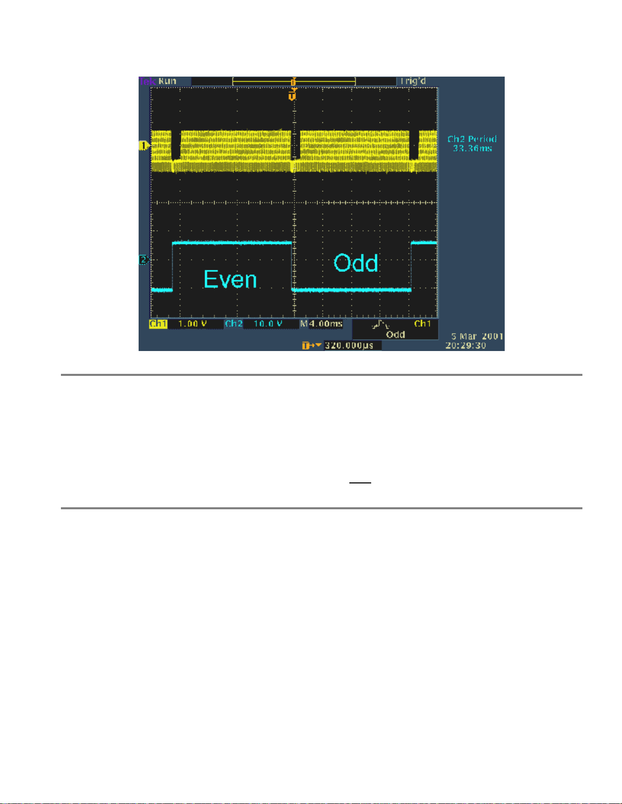
Video vertical synchronization interrupt ........................................................................ 5
Serial Port ....................................................................................................................... 6
Cable Termination .......................................................................................................... 6
Adapter Jumper Options................................................................................................. 7
External connections to ANC-6023.............................................................................. 10
DB9 RS-232C Signals.............................................................................................. 10
DB9 to DB25 pin chart................................................................................................. 10
RS422 connections to ANC-6023................................................................................. 10
DB9 RS-422 Signals for Master (Multimedia Controller) ........................................... 11
DB9 RS-422 Signals for Client (Receive from Master)............................................... 11
Appendix A - Program listing....................................................................................... 12
Appendix B -Troubleshooting...................................................................................... 13
Loopback Test............................................................................................................... 13
CABLING (most common problem)............................................................................. 13
Powering....................................................................................................................... 13
Program Operation........................................................................................................ 13
RS422 Equipment......................................................................................................... 14
Now What?................................................................................................................... 14
Appendix C -Circuit Board Schematic......................................................................... 15

4
Features
•True EIA RS232 and RS422 interfaces
•Full duplex operation
•Baud rates to 1 MBaud
•Uses DB-9 connector on PC serial port by 6’ DB-9MF cable (included)
•Powered from 9v external power supply (included)
•Latest surface mount technology (SMT) for low power and small size
•Pin connections on converted signal side mate directly to many professional multimedia units
(SMPTE interface for Sony, Panasonic, Grass Valley, Ampex, etc.)
•BNC input for composite video to detect vertical sync
Overview
The ANC-6023 adapter convert the RS-232C level signals input and output on a personal computer (PC)
or compatible into bipolar-current RS-422 type signals. The interface voltage levels produced are true
RS232 and RS-422 type signals. These adapters find wide use in high-speed long distance serial
communications, or to interface a PC with equipment that uses an RS-422 type input/output. The adapter
is powered by an external +5v to 12v DC supply. For some installations, the adapter may be powered
using the serial interface only. Extended cable runs and/or terminated RS-422 connections require more
current than the serial port power can provide. The RS-422 connector can accept +5v to +12v regulated
DC at 150 milliamps to provide the added power to the adapter. The ANC-6023 allows the designer to
apply composite video sync that is readable on the serial port’s Data Carrier Detect (DCD, referred to as
RLSD on some systems) or Ring Indicator (RI) line. Our ANC-6090 RS232/RS422 adapter uses the same
electronics as the ANC-6023. There are several additional modes of RS422 and limited RS485 operation
available. See the ANC-6090 User’s Manual for information on jumper settings for other application
modes.
Mechanical Specifications
Adapter case size:
•ANC-6023 = 2.2” X 2.1”
Connectors:
•Female DB9 to PC (6’ DB-9MF cable to PC is included)
•Female DB9 to RS-422 equipment
•Video Input by BNC type connector

5
Electrical Specifications
•Power requirements = 18 ma for short cable, non-terminated applications 150 ma for long and/or
terminated cable applications
•RS-422 output drive = short proof output, non-terminated operation to 150 feet, terminated
operation with external power supply to 4000 feet.
•RS232 output drive = short proof output, under worse case conditions, 5v switching to exceed 3v
EIA RS232 specification
ANC-6023 Installation
Turn off the personal computer and any other remote equipment before performing the adapter
installation. Never install or remove the adapter with the power applied to the PC or any of the attached
equipment. This could result in permanent damage to the adapter due to static discharge.
The adapter is plugged into the serial port male DB-9 jack on the back of the PC using a 1-for-1 pin DB9
extention cable (6’ DB-9MF cable included). Be sure to look at the label on the adapter to identify and
insure that the proper DB9 is plugged into the PC’s serial jack. The ANC-6023 would be difficult to
connect incorrectly as the RS422 side has the BNC connector also. The user should screw the 2 cable
mounting screws into the serial port’s hex nuts for permanent installations to assure good long-term
connection. The ANC-6023 may require the mounting screws be used as both a DB-9 cable and coax
cable will be installed at the opposite end will exert a force on the adapter. The user of the ANC-6023
should be aware of this, and take the appropriate care with cable strain relieving.
The adapter is attached to the Pc serial port by a extension cable. Remember that the signal is still RS-
232C level leaving the computer and entering the adapter so keep as much of the cable rolled up as
possible. Also note that if the designer is using a DB9 to DB25 adapter (or cable), an A-B selector box or
break-out box for testing, that all 9 pins should be connected through the adapter or test setup. There are
handshake signals that the host system may need and pins 1 and/or 9 may be driving the host with the
video sync edge/frame information.
Video vertical synchronization interrupt
The ANC-6023 user may input and examine the video sync input to synchronize operation of command
outputs to video editing equipment. The interrupt may also be used for sync time delay, type of sync
determination and presence of valid video sync.
The process is as follows:
1. Enable desired interrupts under software control in initialization.
2. When interrupt is requested, save all registers upon vectored entry.
3. Input modem status register to determine F1/F2 source of interrupt

6
4. Do interrupt service routine.
5. Restore all registers, re-enable software interrupts and return to main program.
Photo shows an NTSC video signal and the RS232 output going back to the PC’s DCD line.
Serial Port
In addition to the recommended external power supply, 3 of the PC’s serial port RS-232C level signals are
used by the Antona adapter to derive power from; RTS, DTR and TX. The user must insure that the RTS
and DTR signals from the PC’s serial port are brought to a high output level 100 ms before
communicating over the adapter. Usually this is performed once during the user’s program initialization.
Cable Termination
For installation cable lengths greater than 150 feet, resistor termination across the receive pair end of the
cable may be necessary. Use a resister value that matches the impedance of the wire being used (120
ohms). If the user wishes to DC decouple the transmit signals, thereby significantly lowering the current
used by the adapter. It is suggested that a 1000pf capacitor be placed in series with the TX- signal on the
RS-422 side of the adapter. Alternatively, an external DC power supply may be feed into pin 9 on the RS-
422 connector to supply the additional current that the adapter is unable to draw from the RS-232 side of
the interface. Note that some multimedia equipment has internally connected circuitry for resister
termination. So even if the separation distance is less than 150 feet, it may be necessary to provide the
recommended external source of DC power. Some equipment also allows the user to disconnect the
internal termination network.

7
Adapter Jumper Options
figure 1 - ANC-6023 jumper locations
When shipped, the ANC-6023 is set for transmit and receive always. The output pins are set for
‘master’, the terminating resister is disconnected and video sync is connected to DCD (JP7).
All references to ‘horizontal’ and ‘vertical’ below are in respect to figure 1 above. The schematic
gives another view of each jumper showing the settings on isolated block drawings of each jumper
function.
To open the enclosure hood use a small flat blade screwdriver and carefully pry the plastic latches on one
side of the enclosure and gently separate the sides slightly (about .020”). Place a paper clip or coin
between the separated sides of the enclosure to keep it from re-latching shut while you repeat the process
on the two plastic latches on the other side of the hood. The two sides of the hood should now come apart.
Best to leave the shell off of the adapter top while doing the initial setup. Then snap the top on after the
adapter is configured and working properly.
To reassemble the enclosure hood back around the adapter electronics, place the circuit board into the
enclosure half that designates signal direction with the RS-422 connector (the DB-9 connector end that
shares the BNC) on the arrowed end pointed to by the small “RS-422” designation. Double check that the
hood labeled with “RS-232” and “RS-422” is properly oriented before closing the sides and relatching all
four plastic latches. Remember - the RS-422 end of the adapter is the end with the BNC mounted next to
it.
Transmit Control Enable - JP1
For single adapter, 4-wire RS422 setups where the ANC-6023 is controlling one piece of equipment (most
common with this adapter) , JP1 can be set in the horizontal position, as shipped. The transmit data RS-
422/485 driver lines are always asserted that way. For battery powered applications, it may be desirable to
turn off the transmit drivers to save current when there is no data being transmitted. When using the RTS

8
signal to control driver output, the vertical position should be set. See Appendix C, the middle left hand of
the schematic for the location of JP1. The photo below (photo 1 below) shows how lowering the RTS line
on the RS-232 side of the adapter (lower trace - showing RTS signal after being translated to the TTL
level within the adapter) precedes transmitting the data byte out the TX+ line (upper trace).
Auto Transmit Source - JP2
This jumper is really for the ‘AutoXmit’ feature of the ANC-6085 version adapter and is just left in the
horizontal position (as shipped). See Appendix C, the lower left hand of the schematic for the location of
JP2.
Photo 1 - RTS Transmit Operation
RTS may also be used to turn on/off the receive input lines (see JP3 below). When RTS is used, asserting
the signal ‘low’ to the adapter enables transmitting while RTS ‘high’ enables receiving. Note that DTR
must be set high when RTS is low in order for the adapter to operate when an external power supply is not
being used.
Receive Enable - JP3
This 3-pin straight vertical jumper can be set to enable receiving RS-422/485 data always (as shipped, JP3
set on the lower and middle pin), or turned off automatically whenever the transmit driver is set active by
RTS (JP3 set on the middle and upper pin). See Appendix B, the middle left hand of the schematic for the
location of JP3. On a 2-wire interface if data is being transmitted and the receiver is also enabled, anything
transmitted will be ‘looped-back’ into the serial port. Since the echoed signal is the actual data that was
transferred to the interface cable, being able to see the transmitted data echoed back may be of use for
testing, authenticating, diagnostics of data output or determining when RTS can be lowered if used to
control transmission.
Cable Termination - JP4
For installation cable lengths greater than 150 feet, resister termination across the remote receive pair end
of the cable may be necessary. The ANC-6090 has a ½W 120 ohm termination resister built in that can be
placed across the receive wire pair by setting jumper 4 (JP4) located over the transmit/receive setting
jumpers. As described above, an external DC power source may be feed into pin 9 on the RS-422/485
connector to supply the additional current that the adapter may need when terminating resisters are
installed on the receive/transmit wire pairs. Note that some multimedia equipment have internally

9
connected circuitry for 120 ohm resister termination. If So, then even if the separation distance is less than
150 feet, it may be necessary to provide an external source of DC. Some equipment also allows the user to
disconnect the internal termination network for short cable runs. See Appendix C, the upper middle of the
schematic for the location of JP4.
Transmit/Receive Pin Reverse Jumpers - JP5/JP6
These two jumper sets, designated JP5 and JP6 on the circuit board and schematic, allow the designer to
swap the transmit and receive pairs on the RS-422/485 side of the adapter. The configuration as shipped
from Antona is set for ‘master’. This configuration is for the adapter acting as a controller to multimedia
type equipment with an RS-422 SMPTE interface. Figure 1 shows the jumper locations from the
component side of the circuit board. The user may move all four jumper shunts on the component side of
the card from the ‘horizontal’ controller configuration to the ‘vertical’ receiver configuration. All four
shunts must be changed to either all horizontal or all vertical for proper adapter operation.
figure 2 - Tx/Rc Pin Reverse Jumpers
JP7 - Video vertical Sync Interrupt Jumper
The ANC-6023 is capable of generating an interrupt on NTSC, PAL or SECAM RS-170 level sync input
with both odd/even field or even field detection. The Data Carrier Detect (DCD, noted as RLSD
sometimes) RS-232C input signal is used for edge detection of both the odd and even video field. It may
be desired in some applications to receive interrupts for field 2 (even field) only detection. The user may
change the output pin from DCD to RI by changing the JP7 jumper. It is set to DCD when shipped.
JP8 - 75 Ohm Video Terminating Resistor Jumper
The user can terminate the video signal to ground with a standard 75 ohm resistor (as shipped), or
disconnect the resistor by removing the JP8 if there is an additional video destination for the signal that is
terminated.

10
External connections to ANC-6023
DB9 RS-232C Signals
Signal Function DB-9 Pin # Comment Data Direction
DCD/RLSD Data Carrier Detect 1 video sync input input to computer
RX RECEIVE DATA 2 RS-232 level input input to computer
TX TRANSMIT DATA 3 RS-232 level output output from computer
DTR Data Term Ready 4 +v to power adapter output from computer
GND GROUND 5 signal ground I/O signal ground
DSR Data Set Ready 6 tied to DTR (pin 4) input to computer
RTS Ready to Send 7 +v to power adapter output from computer
CTS Clear to Send 8 input to computer
RI Ring Indicator 9 alternate video sync input input to computer
DB9 to DB25 pin chart
When using the Antona adapters on a DB25 type com port an adapter can be bought or built to translate
the DB9 connector to accommodate the signals from a DB25 type connector using the table below.
Signal Function DB-9 Pin # DB-25 Pin Comment
DCD/RLSD Data Carrier Detect 1 8
RX RECEIVE DATA 2 3 RS-232 level input
TX TRANSMIT DATA 3 2 RS-232 level output
DTR Data Term Ready 4 20 +v to power adapter
GND GROUND 5 7 signal ground
DSR Data Set Ready 6 6 tied to DTR (pin 4)
RTS Ready to Send 7 4 +v to power adapter
CTS Clear to Send 8 5
RI Ring Indicator 9 22
RS422 connections to ANC-6023

11
cable is normally used to connect from adapter to equipment. The user can hand-wire a 9-pin cable
assembly from the RS-422 piece of equipment to the Antona adapter. The only difference between the
master and client version is the jumper positions of JP1 and JP2 within the adapter. The electronics are
exactly the same, only the 2 transmit and 2 receive signal lines are exchanged.
DB9 RS-422 Signals for Master (Multimedia Controller)
DB9 FUNCTION IDENTIFICATION
1 GROUND ground for RS-422 and/or external power
2 RC- RS-422 minus side input
3 TX+ RS-422 plus side output
4 -not used-
5 GROUND ground for RS-422 and/or external power
6 -not used-
7 RC+ RS-422 plus side input
8 TX- RS-422 minus side output
9 +V Optional +5V to +12V DC @ 150ma
DB9 RS-422 Signals for Client (Receive from Master)
DB9 FUNCTION IDENTIFICATION
1 GROUND ground for RS-422 and/or external power
2 TX- RS-422 minus side output
3 RC+ RS-422 plus side input
4 -not used-
5 GROUND ground for RS-422 and/or external power
6 -not used-
7 TX+ RS-422 plus side output
8 RC- RS-422 minus side input
9 +V Optional +5V to +12V DC @ 150ma

12
Appendix A - Program listing
The following short BASIC program will allow the designer to quickly verify the operation of the ANC-
6023 video sync input. It is assumed that the adapter is plugged into COM1: (use A=&H2FE for COM2:)
with a suitable video input attached to the adapter’s BNC connector input.
10 A=&H3FE
20 PRINT HEX$(INP(A) AND &H80))
30 GOTO 20
The D7 value should toggle with proper operation.
A test driver is also available for download for use with this adapter version. It is a windows based
program and can control a Sony VTR.

13
Appendix B -Troubleshooting
For more general information on troubleshooting an RS232 to RS422 or RS485 interface using our
adapters check with the Application Note page on our website.
Here are the most common sources of interfacing problems specific to the ANC-6023 and tests you can
make:
Loopback Test
You can verify that the Antona adapter is working by doing a simple loop-back test using a male DB9
connector with pin 3 to 7 and pin 8 to 2. Use a simple terminal program to just test that characters sent out
the com port are echoed back through the adapter. Make sure that your terminal program is turning on
RTS and DTR to power the Antona adapter, and that the program is set to control the com port that the
adapter is connected to. The adapter operation does not rely on baud rate, parity, stop bits - but the actual
application program you are using with the adapter may (see PROGRAM OPERATION).
CABLING (most common problem)
If one of the wires used is not connected or shorted, the whole interface will appear not to be working.
Try using another cable or try the loopback test described above with the cable to verify operation. If you
can not get the loopback test to work through the cable, it for sure will not work in your application.
Take a look at the manual of the RS422 equipment that you are trying to control. Be sure that the pin
definitions on the RS422 equipment tells you the signal names, not what they are suppose to connect to.
This sounds simple, but unless you know which direction the pinouts are defined from, you will connect
TX+ to TX+ which is incorrect. Make sure that you have the TX+ on the Antona adapter connected to the
RC+ on the RS422 equipment and TX- connected to RC- (same for the signal coming back from the
RS422 side - make sure that the Antona adapter’s RC+ is connected to the TX+ and that the RC- is
connected to the TX- on the RS422 side. Pin 5 on the Antona adapter’s RS422 output side should be
connected to the ground of the RS422 equipment.
When shipped the Antona adapter is set for a SMPTE MASTER interface (connector pinouts are in the
6023 series manual for both MASTER and client mode, so be sure you are looking at the correct table).
You may also want to open the Antona adapter up and verify the jumpers are set for the mode you desire.
All 4 jumpers should be installed, they each represent one of the 4 signals being transmitted and received.
Powering
Be sure that the external power supply is plugged in - this is the primary power source for the ANC-6023
adapter.
Program Operation
The application program you are using may need some setup performed - selecting the com port, baud

14
lines high to power the adapter). Usually, for multimedia type interfaces, the baud rate is 38.4 Kbaud, Odd
parity, 8 data bits and 1 stop bit. Here again, if the program is not setup right, the adapter will appear not
to be working at all.
RS422 Equipment
Try to verify the operation of the target RS422 equipment independent of the Antona adapter by using
another setup - a different cable connected to another RS422 signal generating device would be the best.
Using a different computer with the Antona adapter would also be a good test.
Now What?
If none of the above seems to fix the problem, but the loopback test works, the adapter is working and
you may now need to connect an oscilloscope up to examine and monitor the RS422 signals and the
RS232 signals being generated by the Antona adapter with the plastic cover removed and running with
your RS422 device and program. Refer to the schematic at in the ANC-6023 User’s Manual you received
with the adapter. It’s easy to put a scope probe onto the tops of the 4 jumpers and verify that RS422
signals are coming and going to the adapter. Test the +power to the adapter by probint the +lead of the
22uf capacitor near the +5v regulator (LM2936). Look for excess noise on any of the lines that might be
fouling up the transmissions.
If the loopback test does not work, check that the right comport is being addressed. Each adapter is tested
prior to shipment with every bit combination of character transmitted and received at 38.4 Kbaud, but like
everything, occasionally they can go bad. Of the hundreds we have shipped, there have been maybe 10 or
so that arrived non-operational. Damaged in shipping or infant component burnout. We do warranty our
adapters, so if it still does not work, call Antona and we will work out an adapter exchange.

15
Appendix C -Circuit Board Schematic
The following page(s) contain the schematic for the series 6023 adapter. The schematic and card artwork are copyright protected by Antona Corporation
and are included only to aid the end user to configure the adapter or for competent technical service personnel to use in maintenance or repair.
Table of contents
Other Antona Adapter manuals