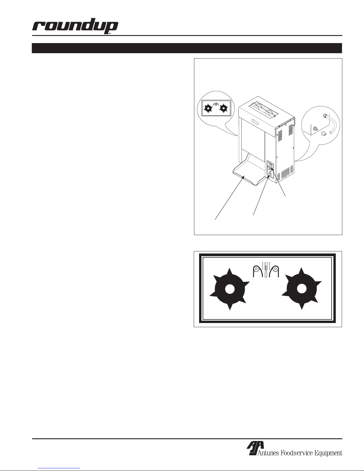
VERTICAL CONTACT TOASTER
4P/N 1010729 Rev. C 05/04
VERTICAL CONTACT TOASTER
5
P/N 1010729 Rev. C 05/04
Throughout this manual, you will find the following safety words and symbols that signify important safety issues with
regards to operating or maintaining the equipment.
WARNING
GENERAL WARNING. Indicates informa-
tion important to the proper operation of
the equipment. Failure to observe may
result in damage to the equipment and/or
severe bodily injury or death.
WARNING
ELECTRICAL WARNING. Indicates infor-
mation relating to possible shock hazard.
Failure to observe may result in damage
to the equipment and/or severe bodily
injury or death.
CAUTION
GENERAL CAUTION. Indicates informa-
tion important to the proper operation of
the equipment. Failure to observe may
result in damage to the equipment.
WARNING
HOT SURFACE WARNING. Indicates
information important to the handling of
equipment and parts. Failure to observe
caution could result in personal injury.
IMPORTANT SAFETY INFORMATION
In addition to the warnings and cautions in this manual,
use the following guidelines for safe operation of the
unit.
• Read all instructions before using equipment.
• For your safety, the equipment is furnished with
a properly grounded cord connector. Do not
attempt to defeat the grounded connector.
• Install or locate the equipment only for its intend-
ed use as described in this manual. Do not use
corrosive chemicals in this equipment.
• Do not operate this equipment if it has a dam-
aged cord or plug, if it is not working properly, or
if it has been damaged or dropped.
• This equipment should be serviced by qualified
personnel only. Contact the nearest Roundup
authorized service facility for adjustment or repair.
• Do not block or cover any openings on the unit.
• Do not immerse cord or plug in water.
• Keep cord away from heated surfaces.
• Do not allow cord to hang over edge of table or
counter.
The following warnings and cautions appear throughout
this manual and should be carefully observed.
• Turn the unit off, disconnect the power source
and allow unit to cool down before performing
any service or maintenance on the unit.
• The procedures in this chapter may include
the use of chemical products. These chemical
products will be highlighted with bold face let-
ters followed by the abbreviated HCS (Hazard
Communication Standard). See Hazard
Communication Standard manual for the appro-
priated Material Safety Data Sheets (MSDS).
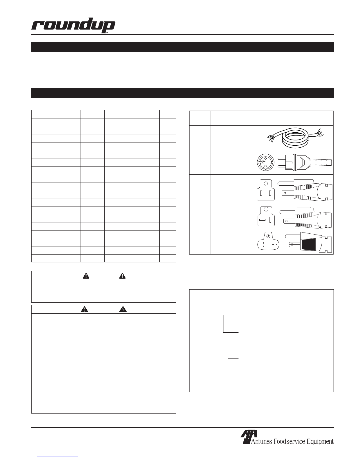
• The toaster should be grounded according to
local electrical codes to prevent the possibility of
electrical shock. It requires a grounded recep-
tacle with separate electrical lines, protected by
fuses or circuit breaker of the proper rating.
• Bread may burn. Therefore toasters must not be
used near or below curtains or other combustible
walls and materials. Failure to maintain safe
operating distances may cause discoloration or
combustion.
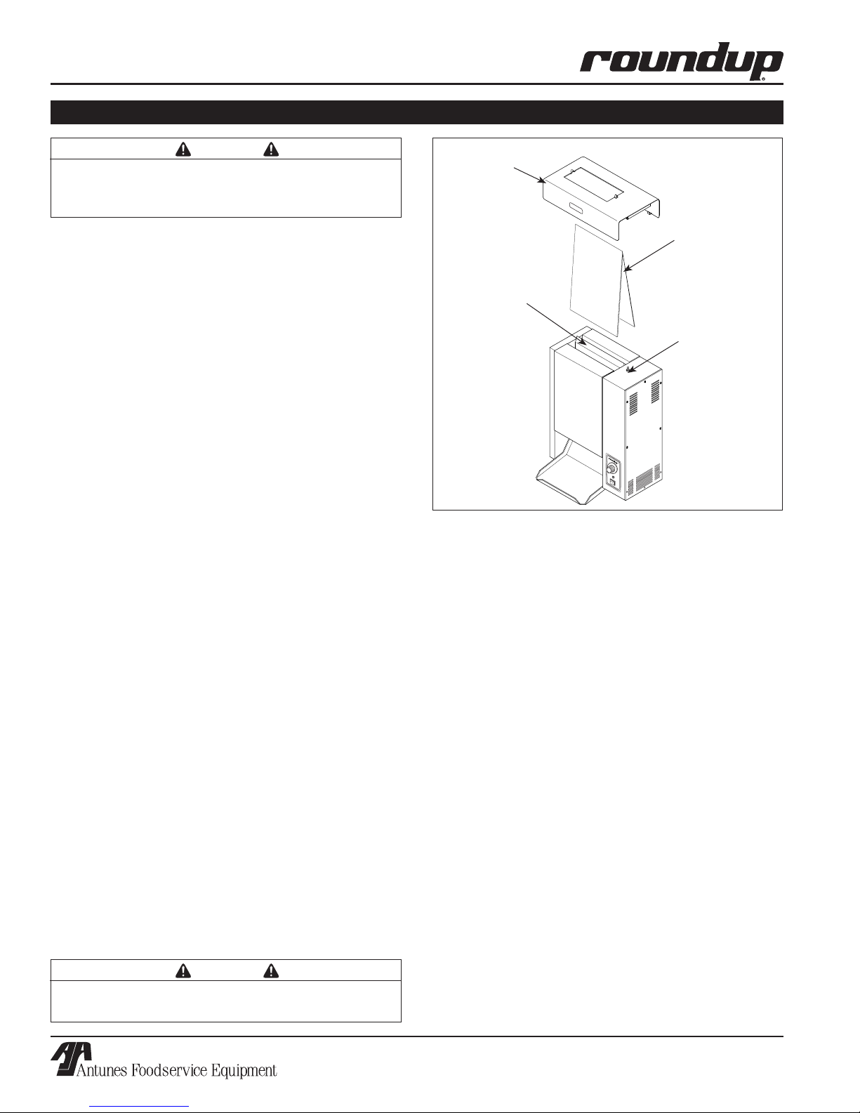
• Failure to use release sheets may result in dam-
age to the equipment and loss of warranty cover-
age.
• All electrical connections must be in accordance
with local electrical codes and any other appli-
cable codes.
• WARNING ELECTRICAL SHOCK HAZARD.
FAILURE TO FOLLOW THESE INSTRUCTIONS
COULD RESULT IN SERIOUS INJURY OR
DEATH.
- Electrical ground is required on this appliance.
- Do not modify the power supply cord plug. If