SAFETY
READ ALL INSTRUCTIONS BEFORE USE. FAILURE TO
FOLLOW THESE PRECAUTIONS COULD RESULT IN INJURY TO
YOURSELF AND OTHERS
1. When this griller is to be positioned in close proximity to a wall,
partitions, kitchen furniture, decorative nishes, etc. it is
recommended that they be made of non-combustible material. If
not, they shall be clad with a suitable non-combustible heat
insulating material, and the closest attention be paid to re
prevention regulations.
2. Do not use an appliance that is damaged, leaking or which does
not operate properly.
3. Ensure that the gas cylinder is connected or changed in well
ventilated area,preferably outdoor, away from any source of
ignition as open ames, and away from other people.
4. Keep gas cylinder away from heat and ames. Do not place on
a stove or any other hot surface.
5. Ensure that the assembled unit is stable and does not rock.
6. Do not cover or change the primary air supply apertures in the
burner as this will aect the performance of the product and may
lead to unstable ames.
7. If there is a leak on your appliance (smell of gas), turn o the gas
supply, rst at the control valve on the cylinder and then on your
appliance by turning the control knobs fully clockwise.
8. If you wish to check for leaks on your appliance, do it outside. Do
not try to detect leaks using a ame. The correct way is to smear
the joint with soapy water. If bubbles form, then there is a gas
leak. Immediately turn o the gas supply rst closing the control
valve on the gas cylinder and then the appliance valves. Check
that all the connections are properly lted. Re-check with soapy
water. If a gas leak persists, return the product to your dealer for
inspection/repair.
9. Do not modify the appliance or use it for anything other than what
it has been designed.
10. During use, part of the appliance will become hot, particularly the
cooking areas and top. Avoid touching hot parts with your bare
hands. The use of oven gloves is recommended.
12. Keep young children away from the appliance at all times.
13. This appliance consumes oxygen and needs ventilation for
optimum performance and for the safety of those in close
proximity.
POSITIONING DIAGRAM
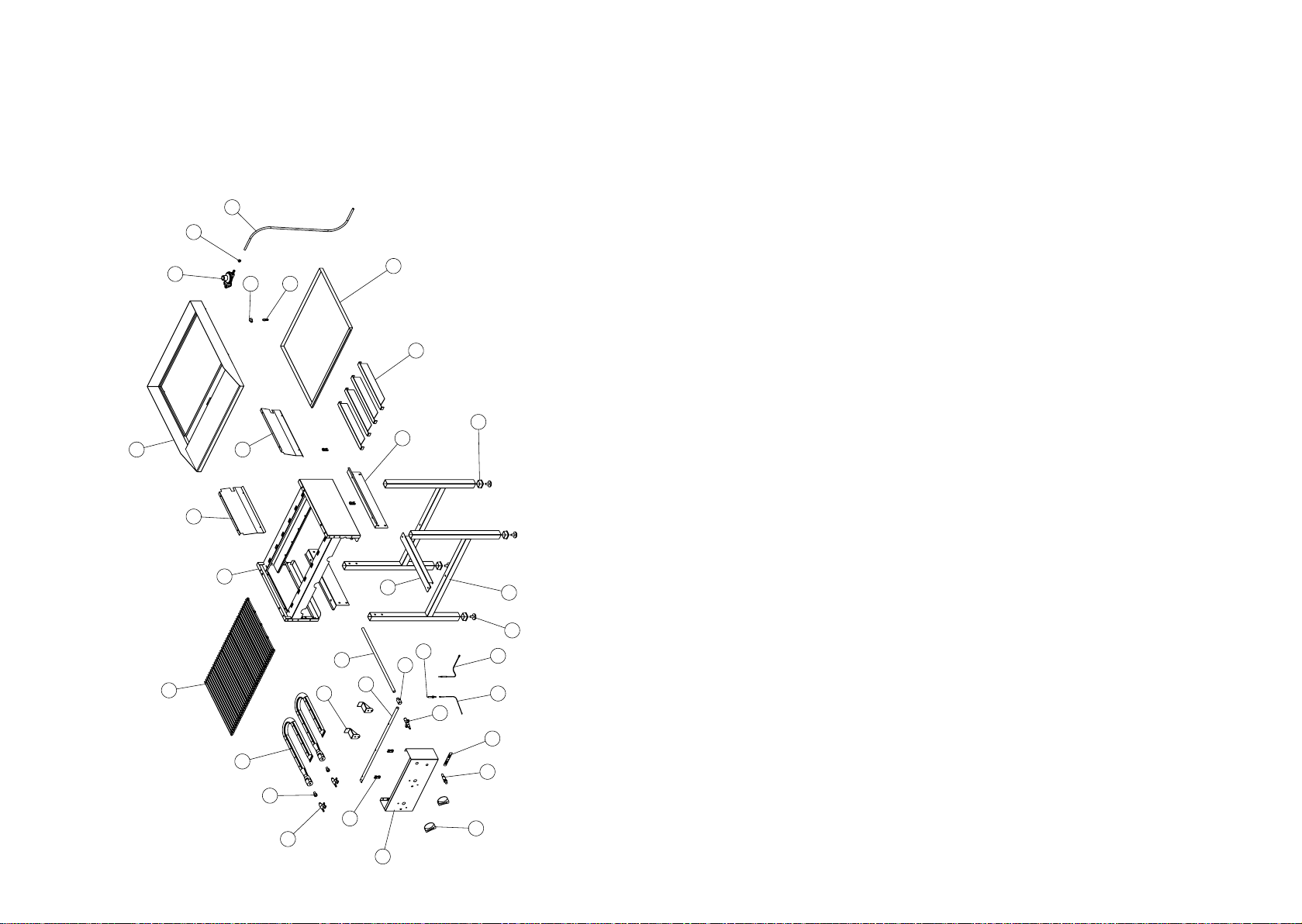
10 RADIANT FREE STANDING GRILLER
MODEL CODE: GGA0010 R04
7 12
791
954
1217