AODELAN FT-8 User manual

Wireless Flash Trigger
无线引闪器
User Manual/使用说明书
FT-8
FT-8(R)
FT-8(T)


Thank you for purchasing an AODELAN
product.
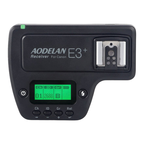
AODELAN FT-8 is a simple and reliable radio flash
trigger. It offers a simple way to use off-camera ash.
The rotating Transmitter can be used upright or in the
low-profile down position. The 8-channel transmitter
and receiver units have a maximum range of 200m
and feature a “re-all” channel function.
Please read this user manual as well as the user
manuals provided with your camera and flash
which works with FT-8 before use.
For your safety
Before using your product, please read the following
safety precaution carefully to ensure correct and safe
use.
Do not disassemble or attempt to repair it.
Do not use the product in the presence of
ammable or explosive gas.
The product is not waterproof. Please keep away
from rain, snow and high humidity conditions.
Do not expose the product to high temperature
over 45℃(e.g. left in a car trunk).
Do not clean the product with organic solvent or
alcohol-based liquid.
Keep the product out of the reach of children.
Consult local authorities on the proper disposal or
recycling of a battery.
• 1 •

Declaration of Conformity USA
Product name: Wireless Flash
Trigger Transmitter
Trade name: AODELAN
Model number: FT-8(T)
FCC ID: 2AEJW-FT8
Manufacturer: Shenzhen
Aodelan Technology Co., Ltd.
Product name: Wireless Flash
Trigger Receiver
Trade name: AODELAN
Model number: FT-8(R)
Manufacturer: Shenzhen
Aodelan Technology Co., Ltd.
FCC Interference Statement
This device complies with part 15 of the FCC Rules.
Operation is subject to the following two conditions: (1)
This device may not cause harmful interference, and
(2) this device must accept any interference received,
including interference that may cause undesired
operation.
FCC Radiation Exposure Statement
This equipment complies with FCC RF radiation
exposure limits set forth for an uncontrolled
environment. This device and its antenna must not be
co-located or operating in conjunction with any other
antenna or transmitter.
FCC Class B Compliance note
This equipment has been tested and found to comply
with the limits for a Class B digital device, pursuant
to Part 15 of the FCC Rules. These limits are
designed to provide reasonable protection against
harmful interference in a residential installation. This
• 2 •

equipment generates, uses and can radiate radio
frequency energy and, if not installed and used in
accordance with the instructions, may cause harmful
interference to radio communications. However, there
is no guarantee that interference will not occur in a
particular installation. If this equipment does cause
harmful interference to radio or television reception,
which can be determined by turning the equipment
off and on, the user is encouraged to try to correct the
interference by one or more of the following measures:
-- Reorient or relocate the receiving antenna.
-- Increase the separation between the equipment and
receiver.
-- Connect the equipment into an outlet on a
circuit different from that to which the receiver is
connected.
-- Consult the dealer or an experienced radio/TV
technician for help.
• 3 •

Parts
Transmitter FT-8(T)
1. Status LED
2. Channel Numbers
3. Channel Adjustment
Buttons
4. Fire All Button
5. Test Button
6. Swivel Rotator
7. Locking Ring
8. Camera Hot Shoe
Connection
9. Power Switch
10. Battery Cover
11. Battery Compartment
Receiver FT-8(R)
1. Status LED
2. Hot Shoe Connection
3. Power Switch
4. DC Power Port
5. Channel Numbers
6. Channel Adjustment
Buttons
7. 3.5mm Output Port
8. Battery Cover
9. Battery Compartment
10. Locking Ring
11. Cold Shoe & 1/4”-20
Tripod Lug
• 4 •

Inserting Batteries
1. Press the battery cover in while pushing it away
from the FT-8 transmitter or receiver. The battery
cover will snap open.
2. Remove the battery cover from the FT-8.
3. Insert AA batteries as shown inside the battery
compartment.
4. Replace the battery cover and push back into the
locked position.
Turning Transmitter and Receiver On/Off
1. To turn on the FT-8 transmitter or receiver - move
the power switch to the “ON” position.
2. To turn off the FT-8 transmitter or receiver - move
the power switch to the “OFF” position.
Connecting the FT-8 transmitter to the
camera hot shoe
1. Turn off the camera and FT-8 transmitter.
2. Slide the FT-8 transmitter into the camera’s hot
shoe mount.
3. Turn the FT-8 locking ring until tight.
4. Turn on the camera, FT-8 transmitter and set the
shooting mode of the camera to Manual.
• 5 •

Connecting a ash to the FT-8 Receiver hot
shoe
1. Turn off the ash and the FT-8 receiver.
2. Slide the ash into the receiver’s hot shoe mount.
3. Lock the ash with the ash’s locking mechanism.
4. Turn on the ash and the FT-8 receiver. *
5. Set the ash to Manual mode.
Connecting a flash/strobe to the FT-8
receiver by sync cable
1. Turn off the ash/strobe and the FT-8 receiver.
2. Connect a cable to the receiver’s 3.5 mm Sync
Port.
3. Connect the opposite end of the cable to a ash
or studio strobe (a 6.3 mm adapter is included for
studio strobes with larger ports).
4. Turn on the ash/strobe and the FT-8 receiver. *
5. Set the ash/strobe to Manual mode.
* It is not unusual for the ash to discharge once after
turning on the FT-8
• 6 •

Precautions for Use
Turn off all devices – flashes/strobes, cameras,
and AODELAN FT-8 transmitters and receivers -
when connecting and disconnecting devices.
FT-8 is designed to work with camera and ash in
manual mode and has no TTL functions.
FT-8 receiver will re hot shoe ashes that are
triggered from the center contact pin.
Some third party ashes that are triggered from
auxiliary hot shoe pins will not be triggered when
used on the FT-8 receiver hot shoe.
Flashes will be triggered via sync cable if the ash
has a sync port.
• 7 •

Raising and Lowering the Transmitter
The FT-8 transmitter can be used in an up or down
position.
1. To lower the transmitter: After mounting, gently
push the FT-8 transmitter forward to use in the
down position. The transmitter will lock in place in
the down position.
2. To raise the transmitter: Gently pull the FT-8
transmitter up. The transmitter will lock in place in
the up position.
Setting Channels
1. The FT-8 has eight channel settings.
2. Press the Channel Adjustment Buttons (left or
right) on the transmitter or receiver to set the
channel.
3. Channel Numbers 1 to 8 will illuminate on the
transmitter or receiver to indicate which channel
the device is set to.
4. FT-8 transmitters will only trigger receivers set to
the same channel.
• 8 •

Fire All Channels Switch
1. To re all ashes or strobes on receivers set to
different channels press the Fire All Button on the
transmitter.
2. The Channel Numbers 1 to 8 will illuminate.
3. All nearby FT-8 receivers set to any channel in
standby mode will re the connected ashes/
strobes.
4. To turn off Fire All mode press the Fire All Button.
The channel selection will revert to its previous
setting.
Test Button
The Transmitter Test Button will test re remote
ashes/strobes.
To Test: Press the Transmitter Test Button –
ashes/strobes connected to FT-8 receivers on the
same channel will re.
Status LED
The Status LED on the front of the FT-8 transmitter
will ash green approximately every one second
when in standby mode. It will turn red when a
signal is being transmitted.
The Status LED on the front of the FT-8 receiver
will ash green approximately every one second
when in standby mode. It will turn red when a
signal is received from the transmitter.
When battery power is low the Status LED on
the transmitter or receiver will quickly ash red
indicating low power and the need to change
batteries.
• 9 •

Specications
Frequency: 2.4 GHz
Range: Max. 200m (656 feet)
Channel: 8 channels and Fire All Function
Power: 2 x AA batteries (Transmitter and Receiver),
5V DC (Receiver)
Max. sync speed: 1/250 sec**
Antenna: internal antenna
Transmitter
Dimensions: Approx. 104 x 50 x 35mm (4.1 x 2.0 x 1.4
in)
Weight: Approx. 68g (2.4 oz) (without batteries)
Receiver
Dimensions: Approx. 88 x 50 x 40mm (3.5 x 2.0 x 1.6
in)
Weight: Approx. 65g (2.3 oz) (without batteries)
Specifications and design are subject to change
without notice.
**On compatible cameras/ashes
• 10 •

This manual suits for next models
2
Table of contents
Other AODELAN Camera Accessories manuals