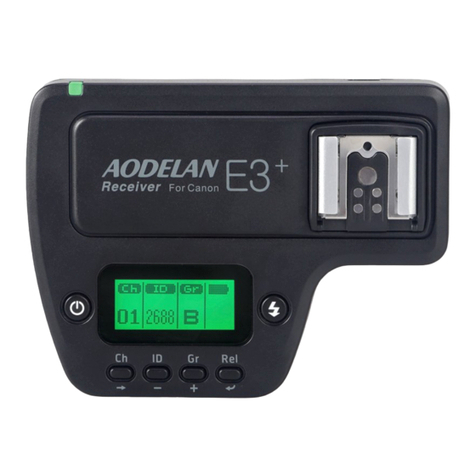
AODELAN TGTE3T User manual

E3+ Wireless TriggerforCanon
Thankyou forpurchasing anAodelan Product
Note: Before usingthe E3+ Wireless Trigger forCanon, please read thisinstruction
manual carefully,while also referringto the instruction manuals of your camera, flash
and other relevant devices.
Warnings
1. This product is aprecise electronic instrument. Do not expose to damp
environments or dust.
2. Please shut down the power of all devices when installingthe wireless trigger.
3. Do not drop or crush.
4. Do not use thewirelesstrigger at flammable,explosive or hightemperature
environment.
5. Do not use harsh chemicals or solvents to cleanthe body.Useasoft cloth or lens
paper.
6. Remove batteries from the wireless trigger if not beingused for an extended
period.
7. Interference: TheE3+ wireless triggertransmits radio signals at 2.4GHz.Its
performancecanbeaffected byelectrical current, magnetic fields, radio signals,
wireless routers, cellularphones, and other electronic devices. Environmental
objects, such as largebuildingsor walls, trees, fences, or cars can also affect
transmission performance. Ifyourwirelesstrigger can tbetriggered,move its
location slightly.
FCC Interference Statement:
This device complies with part 15 of the FCCRules. Operation is subject to the
followingtwo conditions: (1) This devicemaynotcause harmful interference, and (2)
this device must acceptanyinterferencereceived, including interferencethat may
cause undesired operation.
FCC Radiation Exposure Statement:
This equipment complies with FCC RFradiation exposure limitsset forth for an
uncontrolled environment. This device and its antenna must not beco-located or
operatingin conjunction with anyother antenna ortransmitter.
NOTE:This equipment has been testedand found to complywith thelimits for a
Class Bdigital device,pursuant to Part 15 of the FCC Rules. These limits are
designed to provide reasonable protection against harmful interference in a
residential installation. This equipment generates, uses and canradiate radio
frequencyenergyand, if not installed and used inaccordance with the instructions,

maycause harmful interferenceto radio communications. However,there is no
guaranteethat interference will not occur in aparticular installation. Ifthis equipment
does cause harmful interferenceto radio ortelevision reception, which can be
determined byturningthe equipment offand on, the user is encouragedto tryto
correct the interference byone or more of the followingmeasures:
-- Reorient or relocate the receivingantenna.
-- Increase the separationbetween the equipment and receiver.
-- Connect the equipmentinto an outlet on acircuit different from that towhich the
receiver is connected.
-- Consult the dealer or an experienced radio/TVtechnician for help.

E3+ Wireless TriggerforCanon/Transmitter
E3+transmitter is atransmitter for wireless flashshooting.Itcancontrol up to 5
groups (15units) of Canon Speedlites that have awireless multiple flashshooting
function usingradio transmission, as well as non-wireless Canon ETTLSpeedlites by
usingE3+ receiver.Thetransmitter supports multiple flash modes and shooting
approaches includingE-TTLII/E-TTL,Manual, MULTI,Ext.Aand LinkedShooting,
cateringto the diversification of photographylightingdemands.
Table of Contents
I. Parts
II. Preparation Before Use
III. The LCDDisplay
IV. Wireless Flash Shooting:Radio Transmission
1. Wireless Flash Setting
2. ETTL:FullyAutomatic Wireless Flash Shooting
3. UsingFullyAutomatic Wireless Flash
4. ETTL:Wireless MultipleFlash Shootingwith Flash Ratio
5. M:Wireless Multiple Flash Shootingwith Manual Flash Output
6. Multi:
7. Gr: Shootingwith a Different Flash Mode for Each Group
8. Linked Shooting
V. SettingTransmitter Functions with Camera Operations
VI. Customizingthe Transmitter
1.C.Fn: SettingCustom Functions
2.P.Fn: SettingPersonal Functions
VII.Technical Specification
VII. Trouble ShootingGuide

I.Parts
1.<LINK>indication light: Radio
transmission confirmation lamp
2.LCD panel
3.Function Button 3
4. Function Button 2
5. Function Button 1
6.<MODE>: Flash modebutton
7.< >: Charge lamp/Test flash button
8.< >: Select/Set button
9.< >: Select dial
10.Mountingfoot lock lever
11.Batterycompartment cover
12.Function button 4
13. < >: Linked shootingbutton
14.Power button
15.Flash exposure confirmation lamp
16.Lock-release button
17.USBport
18.Remote release terminal
19.Contacts
20.Mountingfoot
21.Lockingpin
22.AFassist light
II. Preparation before use
Installing the batteries

1. Press the batterycompartment cover and
slide it down as shown to open the battery
cover. (Picture 1)
2. Insert the batteries as shown. Make sure
the “+”and“-”batterycontacts are
correctlyoriented as shown. (Note:
Please use 2 pieces of AA alkaline
batteries or AA type NI-MH batteries.
(Picture 2)
3. Replace the batterycoverand push back
into the locked position.
Attaching and Detaching the E3+transmitter
Attachingthe E3+ transmitter to the camera
hot shoe
1. Turn offthe cameraand E3+
transmitter
2. Alignthe E3+ transmitter hot shoe
with camera s hot shoe mount.
3. Slide the E3+ transmitter all the way
into the camera s hot shoe mount.
4. Lockthe E3+transmitter bysliding
the mountingfoot lockleverto the
right until the lock lever clicks in
place.(See picture 3)
Detachingthe E3+Transmitter
1. Lock release: press the lock-release
button while slide the lock lever all the
wayback to the left.(see picture 4)
2. Slide the E3+ transmitter out of camera s
hot shoe mount.
TurnOn/Offthe E3+transmitter
1. Turn On: Press and hold the power button until MENU interface is displayed on
screen.
2. Turn off: Press and hold the power button until the LCD screen goes blank.
1
2

Note: When is displayed, please replace the batteries with new ones.
USB port
The firmwareof E3+ transmitter can be upgraded via the USBport, so as to adjustits
parameter and extend its compatibilitywith cameras to come in the future.
1.1 Connect the USBcable to the computer andthe other end of theUSBcable to
E3+ transmitter sUSBport. Amobile device icon will be displayed on the computer
when successfullyconnected.
1.2 Double click to start the upgrade software. The upgrade softwarecanbe used to
check version info, and upgrade the Base software, RFsoftware and Icon.
Click "Version" icon, thecurrent version information of the connected E3+ transmitter
will be displayed in the software window.
Click "Basesoftware"icon, locate and doubleclick on theFDS file from the pop-out
window.Then it starts loadingthe new firmware.
Click "RFsoftware"icon, locate and doubleclickon the RFCfile from the pop-out
window.Then it starts loadingthe new firmware.
Click "Icon"icon, locateand double click on theFIF file from the pop-out window.
Then it starts loadingthe new firmware.
1.3 The status of theupgrade will bedisplayed inthe process bar.Whencompleted,
an “UpdataOK”will be displayed at the bottom of the upgradesoftwarewindow,and
a “Download OK”will be displayedon thetransmitter sLCD screen. Upon
completion, disconnect the USBcable and restart the E3+ transmitter.
Note:
Please ensurestable power supplywhen attemptingto upgradethe E3+ transmitter..
Loss of computer power duringthe upgrade process could fail the upgrading.
Check Version info on E3+ transmitter
You can check the present version information onE3+ transmitter: while pressingthe
power button to turn on the transmitter,press theflash <MODE> button simultaneously
until the version info is displayed on the LCD screen.
<>: Charge Lamp/Test Flash Button
1. The charge lamp lights when the wireless shooting (slave) is ready.
2. Duringwireless shooting, master unit schargeupwill be lit when all slaveunits
are fullycharged.
3. Duringwireless shooting, you can press the transmitter s charge lamp (testflash
button to fire a test flash.

Remote Release fromSlave Unit
When performingwireless shooting,E3+ transmitter supports remote release (remote
control shooting)from aflash set or E3+ receiver as aslaveunit. For operations, see
the flash or E3+ receiver s instruction manual.
Note
When usingtheremotereleasefunction, the slave unit cameramight need ashutter
release cable(available separately) dependingon the camera models.
1) EOS digital cameras since 2012 do not need to useshutter release cable.
2) EOS cameras before 2012, which are compatible with E-TTLII/E-TTLautoflash
and come with N3 typeremote terminal EOS, shutter release cable will be needed
for linked shooting.
Test Flash froma slave unit
You canfireatest flash from aflash set asaslave unit. Foroperations, see the flash s
instruction manual.
Note: When two or moreunits are set to master,the unit with the <LINK>lamp lit in
green is the one that fires.
Modeling Flash
1. ModelingFlash from a Master Unit
When the camera sdept-of-view preview button is pressed, the flashwill fire
continuouslyfor 1sec. This is called the modelingflash. Itenables youto see the
shadow effects of theflash on the subject and the lighting balance. Besides, youcan
also fire the modelingflash bypressingthe chargelamp/test flash button on E3+
transmitter (the operation required to be enabled inadvance bysettingC.Fn02).
2. ModelingFlash from a Slave Unit
With EOSdigital camerasreleased since 2012, youcan fire the modelingflash from a
flash set as a slave unit. For the operations, see the flash s instruction manual.
AFassist light
Inlow light/contrast situation, the E3+ transmitter sbuilt-in Auto FocusAssist Light
will illuminate to assist with AF.TheAFAssist Light on the front ofthetransmitter
will project afocusingtarget on thesubject. As laser light,the AFassist light hasthe
advantagesof better directionality,less decayandbetter assist performancecompared
with LED type AFassist light. You can chooseto enable or disable the AFassist light
bysettingP. Fn 08.
Note: The laserAFassistlight is safe with optical power less than 5mW. However,
please still avoid pointing the light at human eyes.
Memory Function

E3+transmitter supportsmemoryfunction. Youcan save the wireless settingsand
recall the settinglater.
1. Press function button 4 until is displayed.
2. Save or load the settings
Press function button 3correspondingto , and then pressfunction button 1
correspondingto , the settingsaresaved (stored in the memory).Press function
button 2 correspondingto , the settings that were saved are set.
Clearing TransmitterSettings
You can return the settings for wireless shootingto their default settings.
Press function button 2and 3simultaneouslyfor 2seconds or longer,the transmitter
settingare cleared and the shootingmode returnsto <ETTL>flash mode. Note that
even when thesettingsare cleared, the transmission channel, the wireless radio ID
and the C.Fn and P.Fn settings are not canceled.
III. MENU Functions
1. FEB level ±3EV(in 1/3-stop increments)
2. Flash exposure
compensation ±3EV(in 1/3-stop increments)
3. C.Fn function C.Fn-01 to 22
4. Flash Ratio
ETTL
RATIOA:BC
RATIOA:B
RATIO OFF
A:Bratio
setting:
8:1 to 1:8, in
1/2-stop
increments
M/Multi
RATIOA:B:C
RATIOA:B
RATIO OFF
5. Scan function Scan the radio receptionstatus and setthe
master unit stransmission channel
automaticallyor manually.
6. Wireless radio ID 0000-9999
7. Transmission
Channel Ch.1-Ch.15andAuto
8. MemoryFunction Save the present setting
Load the settings that were saved
Back to shooting-readystate
9. Sync Mode
Enable High SpeedSync
No displayFirst Curtain Sync

10 Firing group Up to 5firing groups A、B、C、D、E(at Gr
mode)
11 Multi Stroboscopic
Flash Frequency 1-500Hz
12. Multi Stroboscopic
Flash Number 1-100times, based onthefrequencyand flash
output
LCD Display
E3+transmitter sLCDdisplaycomes with fivemodes: ETTL、M、MULTI、Gr and
LINKED SHOT.You can cycle through “ETTL、M、MULTI、Gr”bypressing <MODE> button.
And bypressing and holding < >button, you can switch the LCD to displayLINKED SHOT.
Different displaysettings cometo performdifferent flashmodes. Find detailsabout the fiveflash
modes as following
1. ETTL/ETTLII autoflash
Ch: Channel
AUTO: Channel Automatic setting
: Master
:Radiotransmission
wireless shooting
: Sync speed warning
: Beep
:High
Speed Sync;
:CustomFunctions
: Slave flash ready
:FlashExposure
Compensation andFlash
Exposure Compensation amount
Personal Functions
RATIO
:
RATIO OFF
,
RATIO A:B
,
RATIO A:B
C
FiringGroup
Flash ratio
Flash exposure level
: FEB and FEB
sequence
E-TTLⅡ/E-TTLautoflash

2. Manual Flash
3. Stroboscopic Flash
4. Group Firing
Manual Flash Output
M: Manual Flash
Number offlashes Flash frequency
MULTI: Multi (Stroboscopic) flash

5. Linked Shooting
Note: 1) The displaywillshow onlythe settings currentlyapplied.
2) The functions displayed above functionbuttons 1to 4, such as and
Three flash modes optional:
ETTL、M、Ext.A
Gr: FiringGroup
:SLAVE, Slave unit;
MASTER, Master unit;
LINKED SHOT:Linked
Shooting

, changeaccordingto thesettings status.
3) When a button or dial is operated, the LCD panel illuminates.
IV. Wireless Flash Shooting: RadioTransmission
Note:
The transmitterattachedto the camerais calledthe masterunit, andaflash that is
wirelesslycontrolled is called the slave unit.
When the camera sshootingmode is set tofullyautomatic mode or an Image Zone
mode, the operations below are not available. Please set the camera sshootingmode
to P/Tv/Av/M/B(Creative Zone mode).
Wireless Flash Shooting
Usingatransmitter and Canon Speedlites compatible with radio transmission wireless
shootingmakes it easytoshoot with advanced wireless multiple flash lighting,in the
same wayas normal E-TTLⅡ/E-TTLauto flash shooting.
The settingsofthe transmitter attached to the camera (master)areautomatically
reflected on the flash that is wirelesslycontrolled(slave). Therefore, you do not need
to operatetheslave unit while shooting.You can thenperform wireless E-TTL
II/ETTLautoflash shootingjust bysettingthe master unit to ETTLmode.
You canchooseto perform autoflashshootingusingoneslaveunit only,or perform
wireless multiple flash shootingusingtwo or more(up to 15) slave units.
The slaveunits canbespeedlites that is compatible with radiotransmission wireless
shootingand set on slave mode, and also, byusingwith E3+ receiver,other Canon
ETTLflashes that are incompatible with the radio transmission wireless function.
Master Unit Slave Unit
E3+Transmitter
Canon Speedlites that have awireless flash shootingfunction
usingradio transmission, like 600EX-RT (Slave mode).
E3
+
receiver+Canon ETTLFlash(Non-wireless mode)
Note:
1) When usingE3+receiver as slave unit, restrictions will applyto parts of its
functions. And parts of the operations would also be different. For details, see the
instruction manual of E3+receiver
2) When performing radio transmission wireless flash shooting,restrictions may
applyto the flash mode, maximum flash sync speed (referred to below as the “flash
sync speed”) and high-speed sync function, dependingon the camera that you use.
Wireless Settings

To perform wireless shooting, set the E3+transmitter(master unit)and flash(slave unit)
with the followingprocedure.
1. Master unit setting: Check that is displayed.
2. Slave unit setting:Forthe slave unit setting,see the flash or receiver sinstruction
manual.
3. Transmission Channel/Wireless Radio IDSettings: Toavoid interference with
wireless multiple flash systems usingradio transmission that are used byother
photographers or with other devices that use radiowaves (wireless), you can change
the transmission channel and wireless radio ID.
Use the followingprocedures to set the masterunit stransmission channel and
wireless radio ID. Set the same channel and IDfor both the master unit and slave unit.
For the slave unit settings, see the flash s instruction manual.
1. Press function button 4 until is displayed.
2. Set achannel: press function button 1corresponding
to , turn < >to select from Ch. 1-15 or
Auto, and press < > button to finish the setting.
3. Set wireless radio ID:press function button 2
correspondingto ,turn < >to select the
digit to be set and press< >button. Again turn <
>to select anumberfrom 0-9, and press the <
> button.
4. Repeat step 4to set the four IDdigits onebyone.
Press function button 4for correspondingto
to return to the shooting-readystate.
5. When the transmission between themasterunit and
slave unit is established, the <LINK>lamp lights
green.
4. Scanningthe Master UnitTransmission Channels to Set
E3+transmitter isable toscan the radio reception status and set the master unit s
transmission channel automaticallyormanually.When the channel is set to “AUTO”,
the channel with thebest reception signal is automaticallyset. When settingthe
channel manually,you can set the transmission channel again while referringto the
scan results.

1. Scanning while “AUTO”is set:
Pressfunction button 4to display , and thenfunction
button 3corresponding to .The channel is reset to one
with a good reception signal.
2. Scanning while Ch.1to 15 isset:
Pressfunction button 4to display , and thenfunction
button 3correspondingto .The radio reception status is
displayed in agraph. The higher the peak of the channel in the
graph, the better the radio reception signal.
Turn< >to select fromCh.1 to 15, andpress< >button to
return to shooting-readystate.
The color of <LINK>lampchanges depending onthe transmission status of the master unit and
the slave unit.
Note: 1).Ifthe transmission channels of the master unit and slaveunit are different, the slaveunit
does not fire. Set both to the same number, or set both to“AUTO”.
2).Ifthe wireless radio IDs of themaster unit andslaveunit aredifferent, theslaveunit
does not fire.
ETTL: FullyAutomaticWireless Flash Shooting
E3+transmitter attachedto the camera (master) and awirelesslycontrolled flash
(slave) can perform fullyautomatic wireless shooting.
1. Autoflash ShootingUsingOne Slave Unit
Color Status Description Action
Green Lit Transmission OK-
Red
Lit No connected Checkthe channel andID
Blinking
Too manyunits
Master Units +slaveunits =16units
or less
Error Turn the power off and on again

1.1 Set the flash as the slave unit: For the slave unit setting,see the flash or the
E3+receiver sinstructionmanual. Set A, BorCas the firinggroup. Ifsetto Dor E,
the flash does not fire.
1.2 Check the channel and ID: Ifthe channels and IDs of the master unit and slave
unit are different, set them to exactlythe same number.
1.3 Position the camera and the slave unit within the range of wireless radio
transmission.
1.4 Set the flash mode to<ETTL>: Press the<MODE> button on master and set the
flash mode to <ETTL>.The slave unit is set automaticallyto<ETTL>duringshooting
via the control form the master unit. For slave units that use E3+ receiver,flashes on
the receiver need not to set to wireless slave mode, but the need to beset to ETTL
mode manuallyduringshooting.
1.5 Check the transmission status and that the flash is ready:
Check that the <LINK>lamp lights green;
When the flash that is setto wireless slave modeis ready,the AF-assist beam emitter
blinks at 1-second intervals;
Check that the < > slave flash-readyicon is lit on the master unit sLCD panel;
When the recyclingof allthe flash units is completed, the master units chargelamp
lights on.
1.6 Check the operation: Press the master unit stest flash button (chargelamp). The
slave unit flash will fire. Ifno, check that it is placed within the operation range.
1.7 Take the picture: Setthe cameraand takethe picture, in the samewayas with
normal flash shooting.Ifastandard flash exposure was obtained, the flashexposure
confirmation lamp lights up (blue) for 2 sec.
2. Autoflash ShootingUsingMultiple Slave Unit
When youneedmoreflash output or youwant toperform lighting moreeasily,you
can increase thenumberof slave units and firethem as asingle flash. Toadd slave
units, use the sameprocedure as “Autoflash ShootingUsingOne SlaveUnit”.Set A,
Bor Cas the firinggroup. The flash will notfire if it is setto Dor E.When the
number ofthe slaveunits is increased, automatic control is performedto fireall
flashes at thesameflashoutput and ensurethat the total flash outputresults in
standard exposure.
Using Fully Automatic Wireless Flash

Flash exposure compensation and other settings set on the E3+transmitter (master unit)
will be automaticallyset in the flash (slave).You don t need to operate the slave unit.
1. Flash Exposure Compensation
Inthesame wayasnormal exposure compensation, you can set exposure
compensation for flash. The flash exposure compensation amount can be set up to ±3
stops in 1/3-stop increments.
1. Press function button 4 until is displayed.
2. Press function button 2 correspondingto , is
displayed and flash compensation amount is
highlighted.
3. Set the flash compensation amount: turn< > to set
the flash compensation amount, and press < >button.
4. ”0.3”indicates 1/3 stops,and”0.7”indicates 2/3 stops
5. Tocancel flash exposure compensation, return the
compensation amount to “±0”.
Note:
1. BysettingC.Fn13, youcan choose to set theflash compensation amount by
turning< > only, without operatingfunction button2 .
2. Ifthe camera sexposure compensation is setto 1/2-stop increments, flash
exposure compensation will be up to ±stops in 1/2-stop increments.
2.FEB
With FEB(Flash Exposure Bracketing)function, you can takethreeshots while
automaticallychangingthe flash output. The settable rangeis up to ±3stops in 1/3-stop
increments.
1. Press function button 4 until is displayed.
2. Press function button 3 correspondingto ,
is displayed and the FEB level displayis highlighted.
3. Set the FEBlevel: turn< > to set FEBlevel and
press < > button.
4.”0.3”indicates 1/3 stops, and”0.7”indicates 2/3 stops.
5. When used together with flash exposure, FEBshooting
is performed based on the flash exposure compensation
amount.

Note:
1)You can choose whether or not to cancel FEBautomaticallyaftershootingthree
shots with FEBbysettingC.Fn03.
2)You can change the orderof FEBsequence bysettingC.Fn04.
3. High-speed Sync
With the high-speed syncfunction, the flash can synchronizewith all shutter speeds.
This is convenient when youwant to use aperture-priorityAE for fill-flash portraits of
a subject.
High-speed sync function is available for EOS digital cameras since 2012 only.
1. Press function button 4 until is displayed.
2. Press function button 2 correspondingto ,
will be displayed on the screen. Check if is lit in
the view finder.
3. Press function button 2 will disable .
4. FEL: FELock
FE(Flash Exposure) locklocks the correct flash exposure settingfor anypart of the
scene. Perform FElock byoperatingthe camera.For the operation, seethe camera
and flash s instruction manual.
5. About Master Units
You can usetwo ormoremaster units (master units +slave units =maximum of 16
units). Bypreparingmultiple cameras with master units attached,you canshoot by
changingcameras while keepingthe same lighting(slave units).
Note that when usingtwoor more master units, the color of the <LINK> lamp varies
dependingon theorderin which the powerwasturned on. The first master (main
master) is green and the second subsequent masters (sub masters) are orange.
ETTL: Wireless Multiple Flash Shootingwith Flash Ratio
1. Autoflash shootingwith Two Slave Groups
You candivide the slave units into two firing groups Aand B,andadjust the lighting
balance (flash ratio) for shooting.The exposure is controlled automaticallyso that the
total flash output of firinggroupAand group Bresults in the standard exposure.

1.1 Set the firinggroup of the slave units
Operate and set the slave unit group one byone. Set one unit to<A>, and set the other
to <B>. For the slave unit settings, see the flash orreceiver s instruction manual.
1.2 Set the ratio mode: Pressthe masterunit sfunction button 4to display .
Press function button correspondingto to set to < >.
1.3 Set the flash ratio: Press function button 3correspondingto , and again
press the function button3while itiscorrespondingto ,turn< >to set the
flash ratio and press< >button. Press function button 4correspondingto
to return to shooting-readystate.
1.5 Take the picture: the slave unit flash at the set flash ratio.
2. Autoflash Shootingwith Thee Slave Groups
You canaddfiringgroupC to firinggroups AandB.C is convenient to setlightingso
as to eliminate the subject sshadow.The setting method is the same as “Autoflash
Shootingwith Two SlaveGroups”
A B

At the ratio mode , group Aand Bcan be set byflash ratio. Group Cis
independent with its flash output level assigned bythe camera.
2.1 Set aflash as firinggroupC: For theslave unit settings, seethe flash s
instruction manual.
2.2 Press the master unit sfunction button 4to display .Press function
button 2 correspondingto to set to < >
2.3 Set flash exposure compensation as required
Press function button 3correspondingto , turn < >and press function button
3correspondingto . Againturn < >and press < >button to set the flash
exposure compensation amount for group C.
Press function button 4 correspondingto to return to shooting-readystate.
3. Slave Group Control
Ifyou need more flash output or wish to perform more sophisticated lighting,you can
increasethe numberof slave units. Simplyset anadditional slave unit to the firing
group (A、Bor C)whose flash output you want to increase. You can increasethe
number of slave units up to 15 units in total.
For example, if you set afiringgroup with three slave units to A, the threeunits are
controlled as a single firinggroupAwith a large flash output.
M: Wireless Multiple Flash Shootingwith Manual Flash Output
When doingmultiple flash shootingwith manualflash output, youcanshoot with a
different flash output settingforeach slaveunit (firinggroup). Set all the parameters
on the master unit.
A:B
C

1.Press <Mode>buttonto set theflash modeto
<M>
2.Set the number of firinggroup:
While is displayed, pressfunction button2
correspondingto to setthe groupsto fire.
The settingchanges as follows each time pressing
the button: ALL( )→A/B ( )
→A/B/C( ).
3.Select afiringgroup:Press function button 3
correspondingto , turn< > to select the
group forwhich you want to set the flash output,
and press < >button.
4.Set the flash output:Press function button3
correspondingto <*±>, turn< >to set the flash
output and press < >button. Repeat step 3and 4
to set the output of all groups
5.Take the picture: each group fires at the set flash
output
MULTI: Stroboscopic Flash
Stroboscopic flash is anadvanced manual flash shootingmethod. When using
stroboscopic flashwith aslow shutterspeed,youcan shoot multiplesuccessive
movements within asingle picture, similar to stop-motion pictures. Instroboscopic
flash, set the flash output, number of flashes, andflash frequency(numberof flashes
per second = HZ).
1. Press masterunit s<MODE>button to set the
flash mode to<MULTI>.
2. Set the numberof firinggroups andflash
output for eachgroup byreferringto manual flash
on the precedingpage.
3. Set the flash frequencyand number of
flashes:
when is displayed,pressfunction button 2
correspondingto , turn< > to set the
number of flashes and press< >button;
This manual suits for next models
2
Table of contents
Other AODELAN Camera Accessories manuals