AOK ISF Series User manual

The lamp cap rotates 360 degrees
1-1
10mm inner
hexagon wrench
Tools:
M12 socket
hexagon screw
Safety rope
Torque of 142Nm
50.0mm
Ø20.5mm Ø416.0mm
Ø13.0mm
Ø13.0mm
130.0mm
Angle: 8°
1-2
Angle adjustment scale:
1-3 1-4 Braket with driver box
Type-U Bracket Installation (Without visor)
Positive (Fixture)
Negative (Fixture)
Ground
(Fixture)
SPD
Driver
InputExternal terminal
Wiring Diagram
Output
M12 screws
U bracket
Fixture body
The first step:
1) Fix the angle of U bracket and fixture body, then adjust
the angle according to the result simulated by computer.
2) Use a special tool and a torque of 142Nm to fix the U
bracket and fixture body with 2 M12 inner hexagon screws,
as shown in Fig. (1), (2) and (3).
Fig. (1)
Fig. (2)
Fig. (3)
The second step:
Use special tools to fix the U bracket and the plate with
driver box on the lamp pole with two M12 screws with a
torque of 142Nm, as shown in Fig (4), (5) and (6).
Fig. (4)
Fig. (5)
Fig. (6)
Conduit
Conduit
WARNING
Before proceeding with installation or service maintenance of this product.
• Disconnect power to reduce electrical shock risk.
• Review the entire Installation Guide.
• Inspect this properly packaged product for any damage that may have occurred during transit.
• Verify product application complies with manufacturer design recommendations.
• Verify the availability of necessary tools and incidental material.
• Verify applicable code requirements. Field assembly and installation are subject to acceptance by local inspection authority.
• Appropriate safety equipment to be determined by end user, per applicable safety standards and precautions.
This procedure is designed as an installation aid. Skilled tradespeople that are familiar with general construction and electrical
installation techniques should peorm the installation. Licensed electricians should provide electrical installation connections.
Installations and connections should be done in accordance with all national and local codes and permits. In no way is this
document intended to construe warranty or fitness of use of the products described, nor is it intended to provide safety instruction
for those installing the product.
Installation Guide
*Due to the constant improvements in product development, individual parameters might change. Please refer to our sales or R&D team for most up-to-date content as
specifications are subject to change without notice.
+1 626-986-4050 (US)
+86 755 2357 9148 (CN)
@2022 AOK LED LIGHT CO., LTD. All Right Reserved.

90°
160.0mm 155.0mm
1-1
8mm inner
hexagon wrench
Tools:
M10 socket
hexagon screw
10mm inner
hexagon wrench
M12 socket
hexagon screw
Safety rope
Torque of 81Nm
Torque of 142Nm
126°
Ø11.5mm
Ø62.0mm
Ø85.0mm
Horizontal rotation
angle: ±63°
Vertical rotation
angle: 90°
1-2
1-3 1-4
Torque of 4.8Nm
Tools:
Angle adjustment scale:
Phillips
screwdriver
M4 cross countersunk
head screw
Phillips
screwdriver
M4 cross countersunk
head screw
20mm wrench
M16 waterproof
connector
Torque of
2.2Nm
Torque of
240Nm
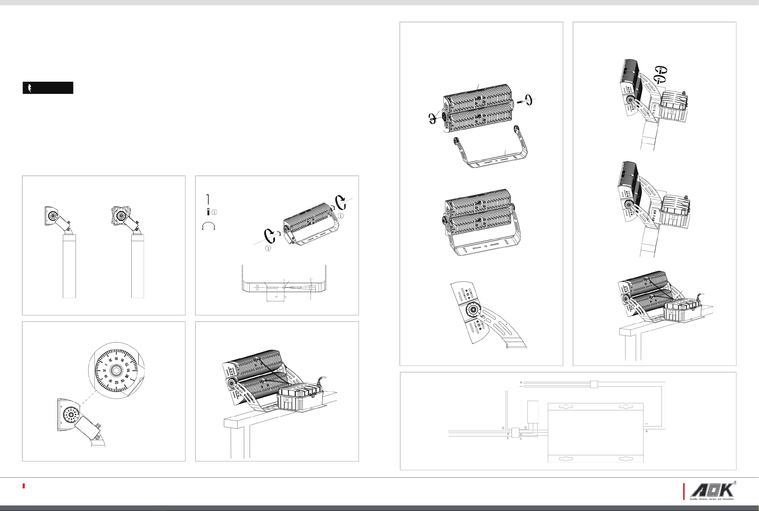
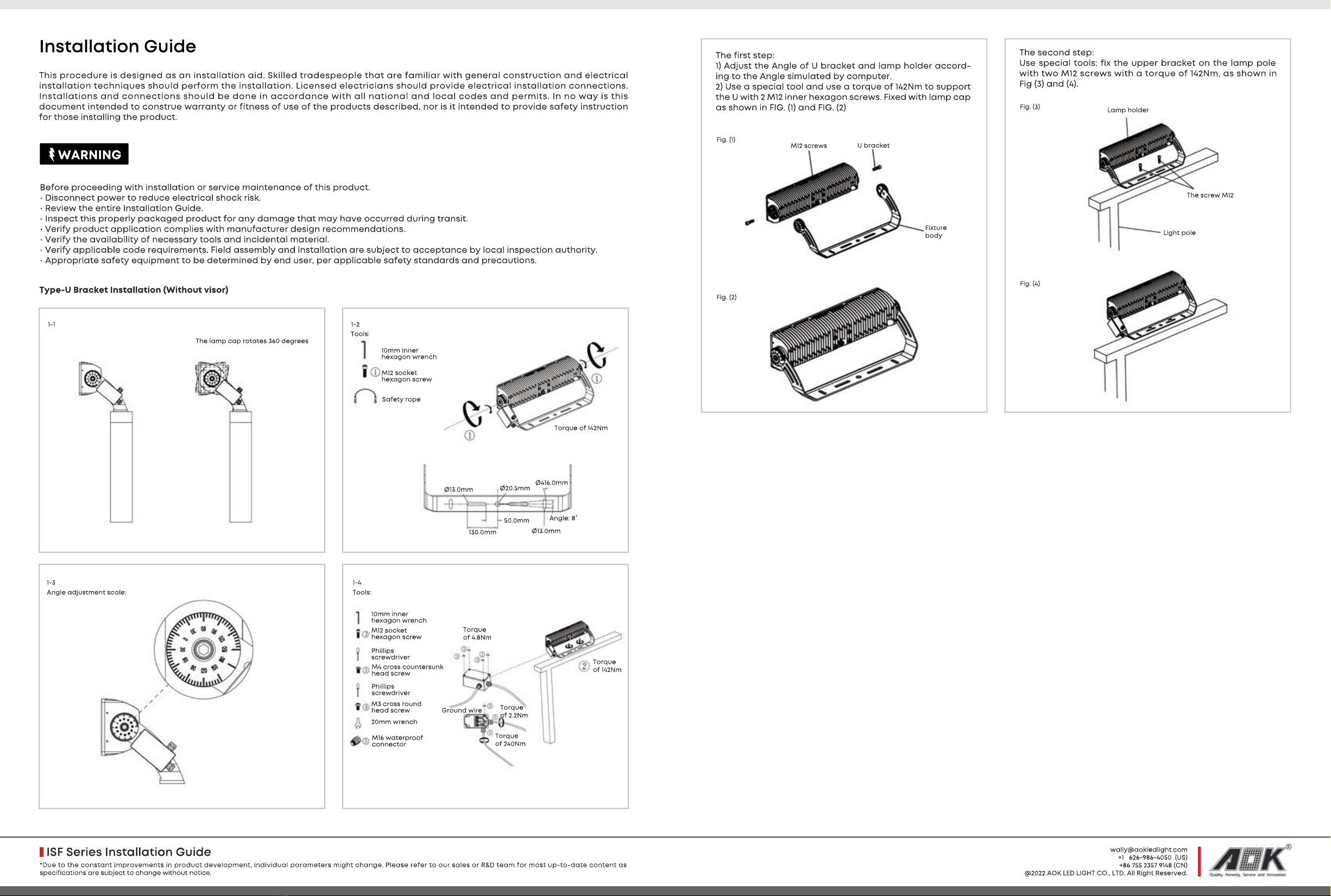
Type-A Bracket Installation (Without visor)
The first step:
1) Fix the lower bracket on the lamp cap radiator with 4 M8
inner hexagon screws with a special tool and a torque of
41NMn, as shown in Fig (1) and Fig (2)
Lower bracket
Cap radiator
M8 screws
Fig. (1)
Fig. (2)
The second step:
1) Adjust the Angle of bracket and lamp pole according to
the Angle simulated by computer.
2) Use special tools: fix the upper bracket on the lamp pole
with two M10 screws with a torque of 81Nim, as shown in
Fig (3) and Fig (4).
Fig. (3)
Fig. (4)
Hanging screws
Screws
Hanging slot
Lamp holder
Fig. (5)
The third step:
First put the lamp holder hanging groove into the mount-
ing screw of the upper bracket, and then fix the lamp
holder and the upper bracket with the M12 inner hexagon
screw, and adjust the installation Angle of the lamp holder
and the bracket according to the design, and then use
special tools: with 142Nmtorque to fix the M12 screw tightly.
Fig (5).
Fig. (6)
Fig. (7)
The fourth step:
Then the lamp holder and the junction box waterproof line
of the male and female head connection is fixed. As shown
in Fig (6) and Fig (7).
WARNING
Before proceeding with installation or service maintenance of this product.
• Disconnect power to reduce electrical shock risk.
• Review the entire Installation Guide.
• Inspect this properly packaged product for any damage that may have occurred during transit.
• Verify product application complies with manufacturer design recommendations.
• Verify the availability of necessary tools and incidental material.
• Verify applicable code requirements. Field assembly and installation are subject to acceptance by local inspection authority.
• Appropriate safety equipment to be determined by end user, per applicable safety standards and precautions.
This procedure is designed as an installation aid. Skilled tradespeople that are familiar with general construction and electrical
installation techniques should peorm the installation. Licensed electricians should provide electrical installation connections.
Installations and connections should be done in accordance with all national and local codes and permits. In no way is this
document intended to construe warranty or fitness of use of the products described, nor is it intended to provide safety instruction
for those installing the product.
Installation Guide
*Due to the constant improvements in product development, individual parameters might change. Please refer to our sales or R&D team for most up-to-date content as
specifications are subject to change without notice.
+1 626-986-4050 (US)
+86 755 2357 9148 (CN)
@2022 AOK LED LIGHT CO., LTD. All Right Reserved.

The lamp cap rotates 360 degrees
1-1
10mm inner
hexagon wrench
Tools:
M12 socket
hexagon screw
Safety rope
Torque of 142Nm
50.0mm
Ø20.5mm Ø416.0mm
Ø13.0mm
Ø13.0mm
130.0mm
Angle: 8°
1-2
1-3 1-4
Ground wire
Tools:Angle adjustment scale:
Phillips
screwdriver
10mm inner
hexagon wrench
M12 socket
hexagon screw
M4 cross countersunk
head screw
Phillips
screwdriver
M3 cross round
head screw
20mm wrench
M16 waterproof
connector
Torque
of 4.8Nm
Torque
of 142Nm
Torque
of 240Nm
Torque
of 2.2Nm
Type-U Bracket Installation (Without visor)
M12 screws U bracket
Fixture
body
The first step:
1) Adjust the Angle of U bracket and lamp holder accord-
ing to the Angle simulated by computer.
2) Use a special tool and use a torque of 142Nm to support
the U with 2 M12 inner hexagon screws. Fixed with lamp cap
as shown in FIG. (1) and FIG. (2)
Fig. (1)
Fig. (2)
Lamp holder
The screw M12
Light pole
The second step:
Use special tools: fix the upper bracket on the lamp pole
with two M12 screws with a torque of 142Nm, as shown in
Fig (3) and (4).
Fig. (3)
Fig. (4)
WARNING
Before proceeding with installation or service maintenance of this product.
• Disconnect power to reduce electrical shock risk.
• Review the entire Installation Guide.
• Inspect this properly packaged product for any damage that may have occurred during transit.
• Verify product application complies with manufacturer design recommendations.
• Verify the availability of necessary tools and incidental material.
• Verify applicable code requirements. Field assembly and installation are subject to acceptance by local inspection authority.• Verify applicable code requirements. Field assembly and installation are subject to acceptance by local inspection authority.
• Appropriate safety equipment to be determined by end user, per applicable safety standards and precautions.
This procedure is designed as an installation aid. Skilled tradespeople that are familiar with general construction and electrical
installation techniques should peorm the installation. Licensed electricians should provide electrical installation connections.
Installations and connections should be done in accordance with all national and local codes and permits. In no way is this
document intended to construe warranty or fitness of use of the products described, nor is it intended to provide safety instruction
for those installing the product.
Installation Guide
*Due to the constant improvements in product development, individual parameters might change. Please refer to our sales or R&D team for most up-to-date content as
specifications are subject to change without notice.
ISF Series Installation Guide
wally@aokledlight.com
+1 626-986-4050 (US)
+86 755 2357 9148 (CN)
@2022 AOK LED LIGHT CO., LTD. All Right Reserved.
Other AOK Outdoor Light manuals
Popular Outdoor Light manuals by other brands

Anslut
Anslut 002-282 operating instructions

Patriot Lighting
Patriot Lighting 343-0421 Assembly and operation instructions

LUMIEN
LUMIEN M4B5-5.5W-27K-R instruction manual

Lighting Technologies
Lighting Technologies NFG 40 P75 manual

LightPro
LightPro Nova 3 117S Manual and safety instructions

LIGMAN
LIGMAN LI-30021 installation manual

LIGMAN
LIGMAN LE-40591 Installation and service manual

Faro Barcelona
Faro Barcelona NASE-1 manual

BEGA
BEGA 84 245 installation guide

Eaton
Eaton Cooper Lighting Night Falcon UFLD Series installation instructions

GHIDINI
GHIDINI TRET quick start guide

HEPER
HEPER TURA LL2036.756-US Installation & maintenance instructions