AOpen AK76D Datasheet

JP12 Onboard Sound
Select Jumper
MIC-In
Line-In
Speaker Out
PC99 Colored Back Panel
PS/2 Mouse
Connector
PS/2 Keyboard
Connector
USB Port
SPP/EPP/ECP
Parallel Port
COM 1 Port COM 2 Port
Game Port
Resettable Fuse
2200μfLow ESR
Condensers
A
TX Power Connecto
r
CPU Fan Connector
A
GP 4x Expansion Slot
462-pin CPU Socket with
Frequency/Voltage
A
uto-detection supports AMD®
A
thlon®and Duron™
600MHz~1GHz+
A
Li
®
Magik 1 Chipset with Pure
A
luminum Heatsink
184-pin DDR SDRAM Slot x2
support maximum up to 2GB
A
TA/33/66/100 IDE Connector x2
FDD Connector
CD-IN Connecto
r
Onboard AC97 CODEC
Modem-CN Connecto
r
AMR Expansion Slo
t
32-bit PCI Expansion Slot x6
2nd & 3rd USB Port Connecto
r
WOM (Wake ON Modem) Connecto
r
WOL (Wake ON LAN) Connecto
r
IrDA Connecto
r
Chassis Fan Connector with
H/W Monitoring
Front Audio Connecto
r
Front Panel Connecto
r
CMOS Data Clear Jumpe
r
2Mbit Flash ROM BIOS 168-pin DIMM Slot x2
support PC100/PC133 SDRAM
maximum up to 2GB
JP21 FSB Select Jumper

Pin 1
1. JP14 Clear CMOS
2. Installing CPU
Everything you need to boot this
motherboard is included in this
Easy Installation Guide. For more
information, a complete Online
User's Manual can be found in
the Bonus Pack CD Disc. Thanks
for the help of saving our earth.
PART NO: 49.89L01.011 DOC. NO: AK76D-EG-E0105A
Hard Drive IDE Cable x 1
80-Wire IDE Cable x 1
Floppy Drive Cable x 1
Bonus Pack CD disc x 1
Norton Anti-Virus CD x 1
This Easy Installation Guide x 1
1. Pull CPU socket lever and up to 90-degree angle.
2. Locate Pin 1 on the socket and look for a black dot o
r
cut edge on the CPU upper left. Match Pin 1 and cu
t
edge. Then insert CPU into the socket.
3. Press down CPU socket lever to finish CPU installation.
You can clear CMOS to restore system default setting. To
clear the CMOS, follow the procedure below.
1. Turn off the system and unplug the AC power.
2. RemoveATX power cable from connector PWR2.
3. Locate JP14 and short pins 2-3 for a few seconds.
4. Return JP14 to its normal setting by shorting pins 1 & pin2.
5. ConnectATX
p
ower cable back to connector PWR2.
Tip: When should I Clear CMOS?
1. Boot fail because of overclocking…
2. Forget password…
3. Troubleshooting…
Normal Operation
(default) Clear CMOS
11
CPU Pin1
CPU socket
Lever
Note: If you do not match the CPU
socket Pin 1 and CPU cut edge well,
you may damage the CPU.

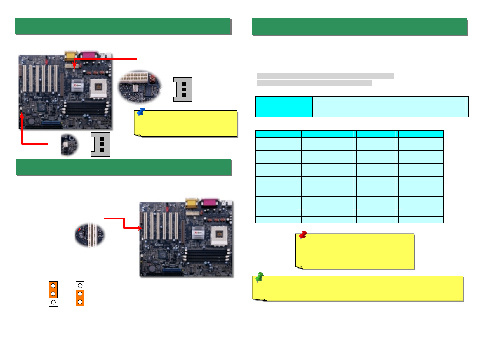
Plug in the CPU fan cable to the 3-pin CPU FAN connector. If you have chassis fan, you
can also plug it on FAN2 (without H/W monitoring) connector.
Disable
1
5. Setting CPU Voltage & Frequency
4. JP12 Enable/Disable Onboard Audio
3. Installing CPU & Housing Fan
Setting CPU Core Voltage
This motherboard supports CPU VID function. The CPU core voltage will be automatically
detected and the range is from 1.1V to 1.85V. It is not necessary to set CPU Core Voltage
Setting CPU Frequency
You can set CPU frequency through the BIOS setup.
BIOS Setup > Frequency / Voltage Control > CPU Clock
Core Frequency = CPU FSB Clock * CPU Ratio
CPU Ratio 2x, 2.5x, 3x, 3.5x, 4x, 4.5x, 5x, 5.5x, 6x, 6.5x, 7x, 7.5x, and 8x
CPU FSB 100~132MHz, 133~166MHz.
CPU FSB (By manual
Adjustment) 100~166MHz by 1MHz stepping adjustment technology
CPU CPU Core Frequency EV6 Bus Clock Ratio
Athlon 600 600MHz 200MHz 6x
Athlon 650 650MHz 200MHz 6.5x
Athlon 700 700MHz 200MHz 7x
Athlon 750 750MHz 200MHz 7.5x
Athlon 800 800MHz 200MHz 8X
Athlon 850 850MHz 200MHz 8.5x
Athlon 900 900MHz 200MHz 9x
Athlon 950 950MHz 200MHz 9.5x
Athlon 1G 1GHz 200MHz 10x
Duron 600 600MHz 200MHz 6x
Duron 650 650MHz 200MHz 6.5x
Duron 700 700MHz 200MHz 7x
Duron 750 750MHz 200MHz 7.5x
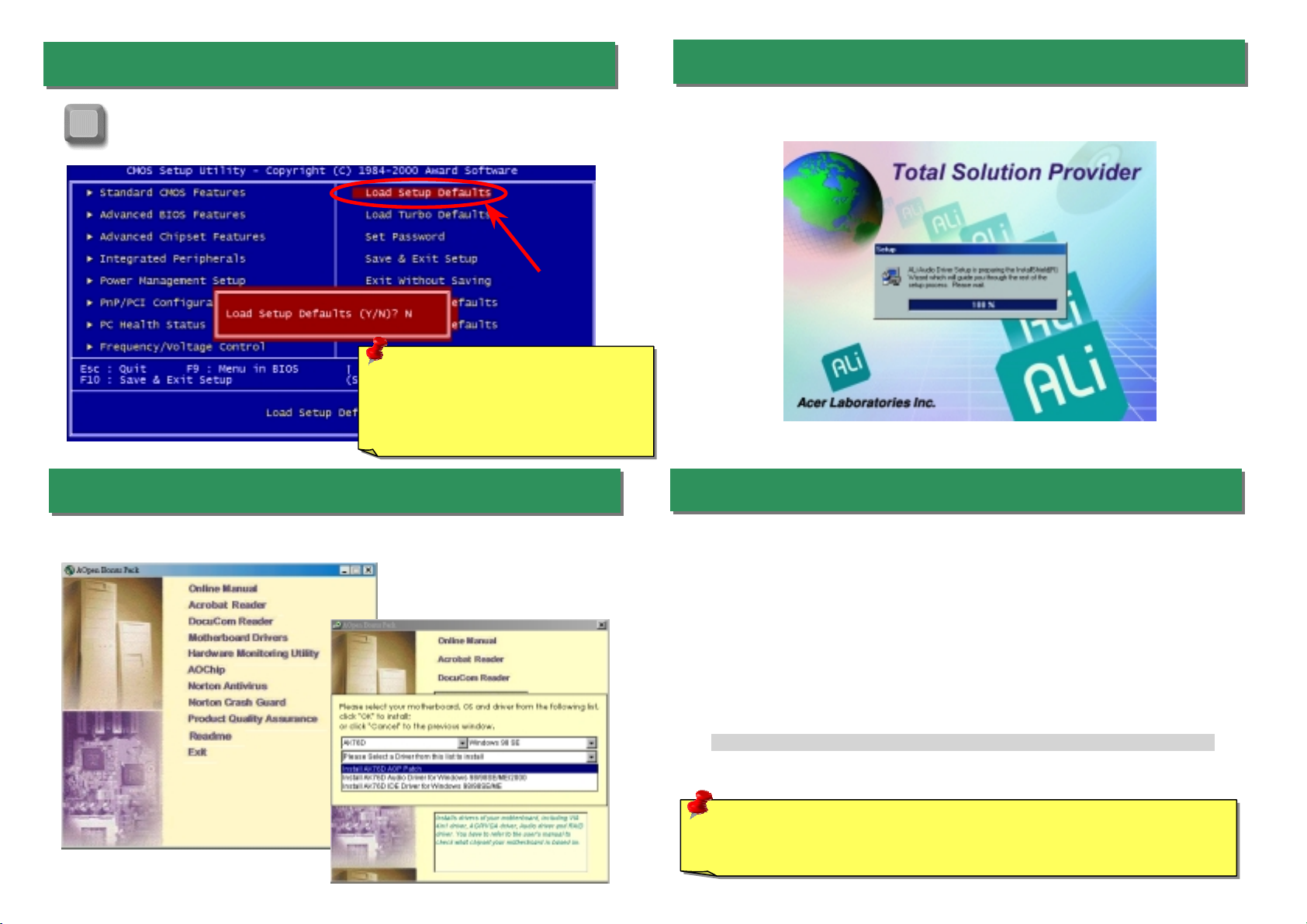
Tip: If your system hangs or fails to boot because of overclocking, simply use
<Home> key to restore the default setting.
Warning: ALi
®
Magik 1 chipset supports
maximum 133MHz FSB and 66MHz AGP
clock, higher clock setting may cause
serious system damage.
GND
+12V
Sensor
Note: Some CPU fans do not have
sensor pin, so that they cannot
support fan monitoring.
Fan2 Connector
CPU Fan Connector
GND
+12V
Sensor
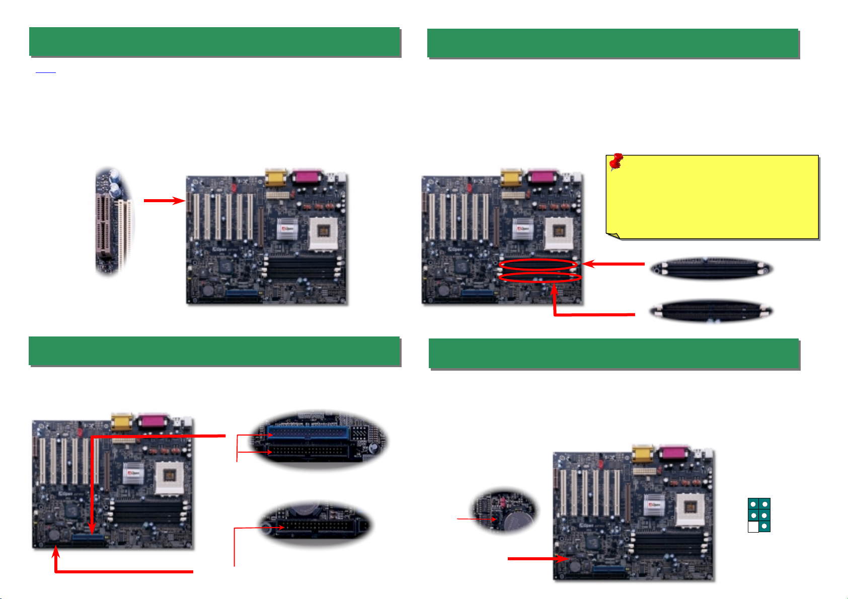
This motherboard hasAC97 sound onboard. JP12 is used to enable or disable onboard
AD1885 CODEC chip. If you select Disable, you can use your preferred AMR sound card.
Enable
(Default)
1
JP12 Enable/Disable
Onboard Sound
Pin 1

Pin 1
Pin 1
8. Install DIMM Modules
6. AMR Expansion Slots
AMR is a riser card that supports sound or modern function. Because CPU computing
power is getting stronger, the digital processing job can be implemented in main chipse
t
and share CPU power. The analogical conversion (CODEC) circuit requires a differen
t
and separate circuit design that is put on AMR card. This motherboard implements sound
CODEC on board (can be disabled by JP12), but reserves AMR slot for the option o
f
modem function. Please note that you can still use PCI modem card.
The DDR SDRAM interface allows zero wait state bursting between the SDRAM and the data
buffers at 200 or 266MHz. The two 184-pin sockets, four banks of DDR SDRAM can be
composed of an arbitrary mixture of 1M/2M4M/8M/16M/32M/64MxN SDRAM with maximum
up to 2GB. Besides, this motherboard is equipped with two 168-pin SDRAM sockets that
allow you to install PC100 or PC133 memory and can go up to 2 GB as well. When you install
both DDR and SDRAM modules, the SDRAM will be automatically detected first; however,
we strongly recommend you not to install both of them at the same time.
DDR
SDRAM
SDRAM
Warning: The AK76D supports both DDR
SDRAM and SDRAM, please do not install
the SDRAM on the DDR SDRAM sockets
and vice versa. Otherwise, it will cause
serious damage on memory sockets or
SDRAM module.
Pin 1
A
TA 33/66/100
IDE Connector
FDD Connector
9. Connect IrDA Connector
The IrDA connector can be configured to support wireless infrared module, with this
module and application software such as Laplink or Windows 95 Direct Cable
Connection, the user can transfer files to or from laptops, notebooks, PDA devices and
printers. This connector supports HPSIR (115.2Kbps, 2 meters) and ASK-IR (56Kbps).
Install the infrared module onto the IrDA connector and enable the infrared function from
BIOS Setup, UART mode select, make sure to have the correct orientation when you
plug in the IrDAconnector.
7. Connecting IDE and Floppy Cables
Connect 34-pin floppy cable and 40-pin IDE cable to floppy connector FDC and IDE
connector. Be careful of the pin1 orientation. Wrong orientation may cause system
damage.
IR
_
T
X
+5V
NC
GND
IR
_
R
X
KEY

The ATX power supply uses 20-pin connector shown below. Make sure you plug in the
right direction.
1
12. Connecting CD / MODEM
11. Connecting Front Panel Cable 13. Front Panel Audio
10. Connecting ATX Power Connector
If the housing has been designed with an audio port on the front panel, you’ll be able to
connect onboard audio to front panel through this connector. By the way, please remove
the jumper cap from the Front Audio Connector before you connect the cable. Do no
t
remove this yellow jumper cap if housing without an audio port on the front panel.
The CD-IN connector is used to connect CDAudio
cable from CDROM or DVD drive to onboard sound.
The Modem-CN connector is used to connect
Mono In/ Mic Out cable from internal modem card to
onboard sound circuit.
MODEM-CN (Red)
Connector Pin1 Pin2 Pin3 Pin4
CD-IN Left GND GND Right
MODEM-CN Mono In GND GND Mic Out
CD-IN (Black)
+5V
+5V
+5V
+5V
+3.3V
+3.3V
+3.3V
COM
COM COM
COM
COM COM
-5V
COM
-12V
PS-ON
PW-OK
+12V
5VSB
Speaker
IDE LED
+
+
+
SPWR
+
+ACPI & PWR
LED
Reset
1
SPWR
GND
ACPI & PWR LED
GND
+5V
NC
NC
GND
RESET
GND
NC
NC
+5V
IDE LED
IDE LED
+5V
+5V
GND
NC
SPEAKER
Attach the power LED, Keylock, speaker, and reset switch
connectors to the corresponding pins. If you enable
“Suspend Mode” item in BIOS Setup, the ACPI & Power LED
will keep flashing while the system is in suspend mode.
Locate the power switch cable from your ATX housing. It is
2-pin female connector from the housing front panel. Plug
this connector to the soft-power switch connector marked
SPWR.
Pin 1
MIC_IN2
VREFOUT
FRONT_R
NC
FRONT_L
GND
+5V
FRONT_R
FRONT_L
1 2
9 10

A
fter you finish the setting of jumpers and connect correct cables. Power on
and enter the BIOS Setup, press <Del> during POST (Power On Self Test).
Choose "Load Setup Defaults" for recommended optimal performance.
14. Power-on and Load BIOS Setup
15. AOpen Bonus Pack CD 17. BIOS Upgrade
AOpen Easy Flash is more user-friendly than traditional flash method. The BIOS binary
file and flash routine are combined together and you simply run a single file to complete
the flash process.
1. Download new BIOS upgrade zipped file fromAOpen's web site. For example,
AK76D102.ZIP.
2. Run shareware PKUNZIP (http://www.pkware.com/) which supports
miscellaneous operation systems to extract the binary BIOS file and the flash
utility. Or Winzip (http://www.winzip.com/) in Windows environment.
3. Save the unzipped file into a bootable floppy disk.
For example, AK76D102.BIN & AK76D102.EXE
4. Reboot the system to DOS mode without loading any memory handler (such as
EMM386) or device driver. It needs around 520K free memory space.
5. ExecuteA:> AK76D102 and the program will do the rest of it.
DO NOT turn off the power during FLASH PROCESS until you are asked to!!
6. Reboot system and press <Del> to enter BIOS Setup, Choose "Load Setup
Defaults", then “Save & Exit Setup” and finish the BIOS upgrade.
Warning: The upgrade of new BIOS will permanently replace your original BIOS
content after flashing. The original BIOS setting and Win95/Win98 PnP information
will be refreshed and you probably need to re-configure your system.
16. Installing Onboard Sound Driver
You can use the autorun menu of Bonus CD disc. Choose the utility and driver and selec
t
model name.
Del
Warning: Please avoid of using "Load
Turbo Defaults", unless you are sure
your system components (CPU,
SDRAM, HDD, etc.) are good enough for
turbo settin
g
.
This motherboard comes with an AD 1885 AC97 CODEC, you can find the audio drive
r
from the Bonus Pack CD disc auto-run menu.

If you encounter any trouble to boot you system, follow the procedures
accordingly to resolve the problem.
Part Number and Serial Number
The Part Number and Serial number are printed on bar code label. You can find this ba
r
code label on the outside packing, on ISA/CPU slot or on component side of PCB. Fo
r
example:
Model name and BIOS version
AK76D R1.00 May. 01. 2001 AOpen Inc.
Award Plug and Play BIOS Extension v1.0A
Copyright © 1998, Award Software, Inc.
Model name and BIOS version can be found on upper left corner of first boot screen
(POST screen). For example:
AK76D is model name of motherboard; R1.00 is BIOS version
Make sure if the jumper settings for CPU and DRAMs are correct.
Clear CMOS.
Install the VGA card. Then connect your monitor and keyboard.
The problem was probably caused
by power supply or motherboard
failure. Please contact your reselle
r
or local distributor for repairing.
Perhaps your VGA card or monito
r
is defective.
No
Yes
No
Yes
It is very possible that your keyboard
is defective.
During system rebooting, press Del to enter BIOS Setup. Choose
“Load Setup Default".
The problem should be caused by the
IDE cables or HDD itself.
Re-install Windows 95, Windows 98 or Windows NT.
Yes
Yes
Turn off the power and unplug the AC power cable, then remove all
of the addon cards and cables, including VGA, IDE, FDD, COM1,
COM2 and Printer.
Turn on the power, and check if
the power supply and CPU fan
work properly.
Start
Check if there is display.
Press Ctrl, and Alt key at the
same time, hold them and then
press Del to see if the
s
y
stem reboots.
Turn off the system and
re-connect the IDE cable.
Check if the system can
reboot successfully.
End
No
No
P/N: 91.88110.201 is part number, S/N: 91949378KN73 is serial number.
Part No. Serial No.
Part No. Serial No.

Dear Customer,
Thanks for choosing AOpen products. To provide the best and fastest service to our
customer is our first priority. However, we receive numerous emails and phone-calls
worldwide everyday, it is very hard for us to serve everyone on time. We
recommend you follow the procedures below and seek help before contact us. With
your help, we can then continue to provide the best quality service to more
customers.
Thanks very much for your understanding!
A
Open Technical Supporting Team
Online Manual: Please check the manual carefully and make sure the
jumper settings and installation procedure are correct.
http://www.aopen.com.tw/tech/download/manual/default.htm
1
1
Test Report: We recommend to choose board/card/device from the
compatibility test reports for assembling your PC.
http://www.aopen.com.tw/tech/report/default.htm
2
2
FAQ: The latest FAQ (Frequently Asked Questions) may contain a
solution to your problem.
http://www.aopen.com.tw/tech/faq/default.htm
5
5
Download Software: Check out this table to get the latest updated
BIOS/utility and drivers.
http://www.aopen.com.tw/tech/download/default.htm
3
3
News Group: Your problem probably had been answered by our support
engineer or professional users on the news group.
http://www.aopen.com.tw/tech/newsgrp/default.htm
4
4
Contact Distributors/Resellers: We sell our products through resellers and
integrators. They should know your system configuration very well and
should be able to solve your problem more efficiently than us. After all, their
attitude of service is an important reference for you if next time you want to
buy something else from them.
6
6
Contact Us: Please prepare detail system configuration and error symptom
before contacting us. The part number, serial number and BIOS version
are also very helpful.
7
7
Web Site: www.aopen.com
E-mail: Send us email by going through the contact form below.
English http://www.aopen.com.tw/tech/contact/techusa.htm
Japanese http://aojp.aopen.com.tw/tech/contact/techjp.htm
Chinese http://w3.aopen.com.tw/tech/contact/techtw.htm
German http://www.aopencom.de/tech/contact/techde.htm
French http://aofr.aopen.com.tw/tech/contact/techfr.htm
Simplified Chinese http://www.aopen.com.cn/tech/contact/techcn.htm
Pacific Rim
AOpen Inc.
Tel: 886-2-2696-1333
Fax: 886-2-8691-2233
America
AOpen America Inc.
Tel: 1-510-498-8928
Fax: 1-408-922-2935, 1-408-432-0496
Europe
AOpen Computer b.v.
Tel: 31-73-645-9516
Fax: 31-73-645-9604
Germany
AOpen Computer GmbH.
Tel: 49-2102-157700
Fax: 49-2102-157799
China
艾尔鹏国际上海(股)有限公司
Tel: 49-2102-157700
Fax: 49-2102-157799
Other manuals for AK76D
1
Table of contents
Other AOpen Motherboard manuals

AOpen
AOpen MK73LE-N Datasheet

AOpen
AOpen AK77-8X Datasheet

AOpen
AOpen s661FXm-7S User manual

AOpen
AOpen i915Ga-E User manual

AOpen
AOpen DX34 Plus User manual

AOpen
AOpen AX6C-L User manual

AOpen
AOpen AX3S Pro Setup guide

AOpen
AOpen MX4SGI-4DL Datasheet

AOpen
AOpen MX3W-E3 Setup guide

AOpen
AOpen MX46LS-V Datasheet

AOpen
AOpen MX6B EZ Installation guide

AOpen
AOpen MX46U2-GN User manual

AOpen
AOpen AP53 User manual

AOpen
AOpen AK79D-400VN Datasheet

AOpen
AOpen MX46L Datasheet

AOpen
AOpen S661FXM-US User manual

AOpen
AOpen AK75PRO Datasheet

AOpen
AOpen AX3S-1394 Datasheet

AOpen
AOpen AX37 PRO Setup guide

AOpen
AOpen MX4PER Setup guide