AOpen MX33 Datasheet

PC-133 SDRAM Slot x 3
Low ESR capacitor
Resettable Fuse
CPU Socket with Voltage
A
uto Detection
Fan2 Connector
(Non-Monitoring)
CPU Fan Connector
(With H/W Monitoring)
A
TX Power Connector
(
With AC Power Auto Recover
y)
JP23 FSB Select Jum
p
er
On-board Sound Back Panel
Modem Audio-In
CD Audio-In
AMR Slot
JP12 On-board Sound
Enable/Disable Jumpe
r
32bit PCI Slot x 3
A
GP 2X Slot
Support 2nd USB Port x 2
IrDA Connecto
r
Chassis Fan Connecto
r
(With H/W Monitoring)
VIAApollo Pro 133 Chipset
Front Panel Connecto
r
2Mbit Flash ROM
multi-language BIOS
W
O
L
C
onnecto
r
WOM Connecto
r
ATA/66 IDE Connector
FDD Connector
Audio Video-In
JP14 Clear CMOS Jumpe
r
Front Panel Audio
PS/2 Mouse
Connecto
r
PS/2 Keyboard
Connecto
r
USB Port
SPP/EPP/ECP
Parallel Port
COM 1 Port COM 2 Port
Game Port
MIC-In
Line-In
Speaker Out

1. JP14 Clear CMOS
2. JP12 Enable/Disable Onboard Audio
Everything you need to boot this
motherboard is included in this Easy
Installation Guide. For more
information, a complete Online User's
Manual can be found in the Bonus
Pack CD Disc. Thanks for the help of
saving our earth.
PART NO: 49.89401.011 DOC. NO: MX33-EG-E0009A
Hard Drive IDE Cable x 1
80-Wire IDE Cable x 1
Floppy Drive Cable x 1
Bonus Pack CD disc x 1
This Easy Installation Guide x 1
Tip: When should I Clear CMOS?
1. Boot fail because of overclocking…
2. Forget password…
3. Troubleshooting…
You can clear CMOS to restore system default setting. To
clear the CMOS, follow the procedure below.
1. Turn off the system and unplug the AC power.
2. Remove ATX power cable from connector PWR2.
3. Locate JP14 and short pins 2-3 for a few seconds.
4. Return JP14 to its normal setting by shorting pins 1-2.
5. Connect ATX power cable back to connector PWR2.
123 123
DisableEnable
1
2
3
Pin 1
1
2
3
This motherboard has AC97 sound onboard. JP12 is used to enable or disable onboard AD1885 CODEC
chip. If you select Disable, you can use your preferred AMR sound card.

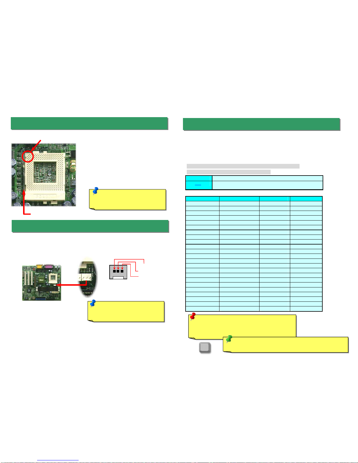
Setting CPU Core Voltage
This motherboard supports CPU VID function. The CPU core voltage will be automatically
detected and the range is from 1.3V to 3.5V.. It is not necessary to set CPU Core Voltage
Setting CPU Frequency
This motherboard is CPU jumper-less design, you can set CPU frequency through the
BIOS setup, no jumpers or switches are needed.
BIOS Setup > Frequency / Voltage Control > CPU Speed Setup
Core Frequency = CPU FSB Clock * CPU Ratio
CPU Ratio 2x, 2.5x, 3x, 3.5x, 4x, 4.5x, 5x, 5.5x, 6x, 6.5x, 7x, 7.5x, and 8x
CPU FSB 66.8, 68.5, 75, 83.3, 100, 103, 112, 117, 124, 129, 133.3, 138, 143, 148,
150MHz.
CPU CPU Core Frequency FSB Clock Ratio
Celeron 300A 300MHz 66MHz 4.5x
Celeron 366 366MHz 66MHz 5.5x
Celeron 400 400MHz 66MHz 6x
Celeron 433 433MHz 66MHz 6.5
Celeron 466 466MHz 66MHz 7x
Celeron 500 500MHz 66MHz 7.5x
Celeron 533 533MHz 66MHz 8x
Celeron 566 566MHz 66MHz 8.5x
Celeron 600 600MHz 66MHz 9x
Pentium III 600E 600MHz 100MHz 6x
Pentium III 650E 650MHz 100MHz 6.5x
Pentium III 700E 700MHz 100MHz 7x
Pentium III 750E 750MHz 100MHz 7.5
Pentium III 800E 800MHz 100MHz 8x
Pentium III 850E 850MHz 100MHz 8.5x
Pentium III 533EB 533MHz 133MHz 4x
Pentium III 600EB 600MHz 133MHz 4.5x
Pentium III 667EB 667MHz 133MHz 5x
Pentium III 733EB 733MHz 133MHz 5.5
Pentium III 800EB 800MHz 133MHz 6x
Pentium III 866EB 866MHz 133MHz 6.5
Pentium III 933EB 933MHz 133MHz 7x
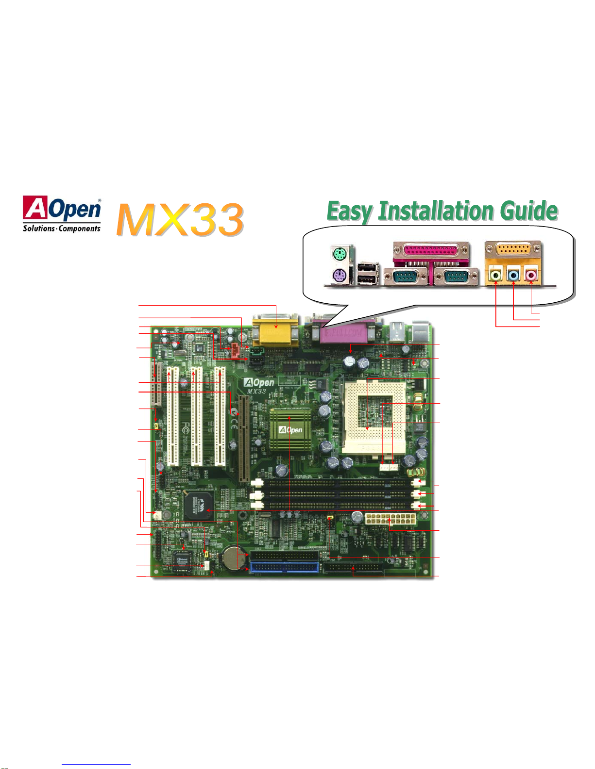
5. Setting CPU Voltage & Frequency
4. Installing CPU Fan
3. Installing CPU
1. Pull up the CPU socket level and up to
90-degree angle.
2. Locate Pin 1 in the socket and look for a
(golden) cut edge on the CPU upper interface.
Match Pin 1 and cut edge. Then insert the
CPU into the socket.
3. Press down the CPU socket level and finish
CPU installation.
Note: If you do not match the CP
U
socket Pin 1 and CPU cut edge well,
it ma
y
dama
g
e the CPU.
CPU socket level
CPU Pin 1 and cut edge
Plug in the fan cable to the 3-pin CPUFAN connector.
GND
+12V
SENSE
Note: Some CPU fans do not have
sense pin, so that cannot support fan
monitorin
g
.Warning: VIA Apollo Pro 133 chipset support
s
maximum 133MHz FSB and 66MHz AGP clock, highe
r
clock setting may cause serious system damage.
Home
Tip: If your system hangs or fails to boot because of overclocking,
simply use <Home> key to restore the default setting.

7. Install DIMM Modules
6. JP23 FSB/PCI Clock Ratio 8. Connecting IDE and Floppy Cable
9. Connecting Front Panel Cable
The JP23 is used to specify the relationship of PCI
and FSB clock. Generally speaking, if you are not
overclockers, we recommend set the jumper at the
default setting.
Auto
(
default
)
PCI=FSB/3
(
100~124MHz
)
PCI=FSB/2
(
133~150MHz
)
1
3
5
7
2
4
6
8
PCI=FSB/4
(
66~83MHz
)
1
3
5
7
2
4
6
8
1
3
5
7
2
4
6
8
1
3
5
7
2
4
6
8
DIMM1
DIMM2
DIMM3
Tip: The driving capability of ne
w
generation chipset is limited due to the
lack of a memory buffer (to improve
p
erformance). This makes DRAM chip
count an important factor to take into
consideration when you install DIMMs.
Unfortunately, there is no way that the
BIOS can identify the correct chip
count, you need to calculate the chip
count by yourself. The simple rule is:
By visual inspection, use onl
y
DIMMs which are less than 1
6
chi
p
s.
Pin 1
This motherboard has three 168-pin DIMM sockets that allow you to install PC100 o
r
PC133 memory up to 1.5GB. Only SDRAM is supported.
Pin 1
IDE1 (Primary)
Secondary
Slave (4th)
Primary
Master (1st)
Primary
Slave (2nd)
Secondary
Master (3rd)
Pin 1
FDD Connecto
r
ATA66 IDE
Connector
Connect 34-pin floppy cable and 40-pin ATA66 or ATA33 IDE cable to floppy connecto
r
FDC and IDE connector IDE1, IDE2. Pin1 of cable is normally marked with red color. Be
careful of the pin1 orientation. Wrong orientation may cause system damage.
A
ttach the power LED, keylock, speaker, and
reset switch connectors to the corresponding
pins. If you enable “Suspend Mode” item in
BIOS Setup, the ACPI & Power LED will keep
flashing while the system is in suspend mode.
Locate the power switch cable from your AT
X
housing. It is 2-pin female connector from the
housing front panel. Plug this connector to the
soft-power switch connector marked SPWR.
1
Speaker
IDE HDD
LED
Keylock
+
+
+
+
SPWR
+
+ ACPI &
Power LED
Reset
1
SPWR
GND
ACPI & PWR LED
GND
+5V
NC
NC
GND
RESET
GND
GND
KEYLOC
K
+5
V
IDE LED
IDE LED
+5
V
+5
V
GND
NC
SPEAKE
R

12. Connecting CD / Modem / Video_Audio_IN
13. Front Panel Audio (Optional)
10. Connect ATX Power Connector
The ATX power supply uses 20-pin connector shown below. Make sure you plug in
the right direction.
11. Connect IrDA Connector
The IrDA connector can be configured to support wireless infrared module, with this
module and application software such as Laplink or Windows 95 Direct Cable
Connection, the user can transfer files to or from laptops, notebooks, PDA devices and
printers. This connector supports HPSIR (115.2Kbps, 2 meters) and ASK-IR (56Kbps).
Install the infrared module onto the IrDA connector and enable the infrared function
from BIOS Setup, UART mode select, make sure to have the correct orientation when
you plug in the IrDA connector.
If the housing has been design with an audio port on the front panel, you’ll be able to
connect onboard audio to front panel through this connector.
GND
NC
Phone_R
Phone_L
NC
FP_Mic
1
2
3
4
5
6
Pin 1
1 +5V
2 NC
3 IRRX
4 GND
5 IRTX
6 NC
The CD-IN connector is used to connect CD Audio
cable from CDROM or DVD drive to onboard sound.
The Modem-CN connector is used to connect
Mono In/ Mic Out cable from internal modem card to
onboard sound circuit.
The Video_Audio_IN connector is used to connect
MPEG Audio cable from MPEG card to onboard
sound.
V
ideo_Audio_In
CD_In
Connector Pin1 Pin2 Pin3 Pin4
CD-IN Left GND GND Right
Modem-CN Mono In GND GND Mic Out
Video_Audio_IN Left GND GND Right
Modem_In Pin 1
Pin 1
PS-ON
+5V
+5V
-5V
COM
COMCOM
COM
-12V
+3.3V
+3.3V
+3.3V
COM
COM
5VSB
PW-OK
COM
+5V
+5V
+12V

A
fter you finish the setting of jumpers and connect correct cables. Powe
r
on and enter the BIOS Setup, press <Del> during POST (Power On Sel
f
Test). Choose "Load Setup Defaults" for recommended optimal
performance.
14. Power-on and Load BIOS Setup
15. AOpen Bonus Pack CD 17. BIOS Upgrade
A
Open Easy Flash is more user friendly than traditional flash method. The BIOS binary
file and flash routine are combined together and you simply run a single file to complete
the flash process.
1. Download new BIOS upgrade zipped file from AOpen's web site. For example,
MX33102.ZIP.
2. Run shareware PKUNZIP (http://www.pkware.com/) which supports
miscellaneous operation systems to extract the binary BIOS file and the flash
utility. Or Winzip (http://www.winzip.com/) in Windows environment.
3. Save the unzipped file into a bootable floppy disk.
For example, MX33102.BIN & MX33102.EXE
4. Reboot the system to DOS mode without loading any memory handler (such as
EMM386) or device driver. It needs around 520K free memory space.
5. Execute A:> MX33102 and the program will do the rest of it.
DO NOT turn off the power during FLASH PROCESS until you are asked to!!
6. Reboot system and press <Del> to enter BIOS Setup, Choose "Load Setup
Defaults", then “Save & Exit Setup” and finish the BIOS upgrade.
Warning: The upgrade of new BIOS will permanently replace your original BIO
S
content after flashing. The original BIOS setting and Win95/Win98 PnP information
will be refreshed and
y
ou
p
robabl
y
need to re
-
confi
g
ure
y
our s
y
stem.
16. Installing Onboard Sound Driver
You can use the autorun menu of Bonus CD disc. Choose the utility and driver and
select model name.
Del
Warning: Please avoid of using
"Load Turbo Defaults", unless you
are sure your system components
(CPU, DRAM, HDD, etc.) are good
enou
g
h for turbo settin
g
.
This motherboard comes with an AD 1885AC97 CODEC. You can find the audio
driver from the Bonus Pack CD disc autorun menu.

If you encounter any trouble to boot you system, follow the
procedures accordingly to resolve the problem.
Part Number and Serial Number
The Part Number and Serial number are printed on bar code label. You can find this
bar code label on the outside packing, on ISA/CPU slot or on component side of PCB.
For example:
Model name and BIOS version
MX33 R1.00 Aug. 04. 2000 AOpen Inc.
A
ward Plug and Play BIOS Extension v1.0A
Copyright © 1998, Award Software, Inc.
Model name and BIOS version can be found on upper left corner of first boot screen
(POST screen). For example:
P/N: 91.88110.201 is part number, S/N: 91949378KN73 is serial number.
MX33 is model name of motherboard, R1.00 is BIOS version.
Make sure if the jumper settings for CPU and DRAMs are correct.
Clear CMOS.
Install the VGA card. Then connect your monitor and keyboard.
The problem was probably caused
by power supply or motherboard
failure. Please contact your reselle
r
or local distributor for repairing.
Perhaps your VGA card or monito
r
is defective.
No
Yes
No
Yes
It is very possible that your keyboard
is defective.
During system rebooting, press Del to enter BIOS Setup. Choose
“Load Setup Default".
The problem should be caused by the
IDE cables or HDD itself.
Re-install Windows 95, Windows 98 or Windows NT.
Yes
Yes
Turn off the power and unplug the AC power cable, then remove all
of the addon cards and cables, including VGA, IDE, FDD, COM1,
COM2 and Printer.
Turn on the power, and check if
the power supply and CPU fan
work properly.
Start
Check if there is display.
Press Ctrl, and Alt key at the
same time, hold them and then
press Del to see if the
s
y
stem reboots.
Turn off the system and
re-connect the IDE cable.
Check if the system can
reboot successfully.
End
No
No
Part No. Serial No.

Dear Customer,
Thanks for choosing AOpen products. To provide the best and fastest service to
our customer is our first priority. However, we receive numerous emails and
p
hone-calls worldwide everyday, it is very hard for us to serve everyone on time.
We recommend you follow the procedures below and seek help before contact us.
With your help, we can then continue to provide the best quality service to more
customers.
Thanks very much for your understanding!
A
Open Technical Supporting Team
Online Manual: Please check the manual carefully and make sure the
jumper settings and installation procedure are correct.
http://www.aopen.com.tw/tech/download/manual/default.htm
1
1
Test Report: We recommend to choose board/card/device from the
compatibility test reports for assembling your PC.
http://www.aopen.com.tw/tech/report/default.htm
2
2
FAQ: The latest FAQ (Frequently Asked Questions) may contain a
solution to your problem.
http://www.aopen.com.tw/tech/faq/default.htm
5
5
Download Software: Check out this table to get the latest updated
BIOS/utility and drivers.
http://www.aopen.com.tw/tech/download/default.htm
3
3
News Group: Your problem probably had been answered by our support
engineer or professional users on the news group.
http://www.aopen.com.tw/tech/newsgrp/default.htm
4
4
Contact Distributors/Resellers: We sell our products through resellers
and integrators. They should know your system configuration very well and
should be able to solve your problem more efficiently than us. After all, their
attitude of service is an important reference for you if next time you want to
buy something else from them.
6
6
Contact Us : Please prepare detail system configuration and error
symptom before contacting us. The part number, serial number and BIOS
version are also very helpful.
7
7
Web : http://www.aopen.com
Email : Send us email by going through the contact form below.
English http://www.aopen.com.tw/tech/contact/techusa.htm
Japanese http://aojp.aopen.com.tw/tech/contact/techjp.htm
Chinese http://w3.aopen.com.tw/tech/contact/techtw.htm
German http://www.aopencom.de/tech/contact/techde.htm
Simplified Chinese http://www.aopen.com.cn/tech/contact/techcn.htm
TEL:
USA 510-489-8928
Netherlands +31 73-645-9516
China (86) 755-375-3013
Taiwan (886) 2-2696-1333
Germany +49 (0) 2102-157-700
Other manuals for MX33
1
Table of contents
Other AOpen Motherboard manuals

AOpen
AOpen AX4SP-G Datasheet

AOpen
AOpen AK79D-400 Max Setup guide

AOpen
AOpen i865PEa-7ILFR Datasheet

AOpen
AOpen AX37D Plus Datasheet

AOpen
AOpen AX63PRO User manual

AOpen
AOpen AX4PER Setup guide

AOpen
AOpen AK76D User manual

AOpen
AOpen MK79G-N User manual

AOpen
AOpen MX4SGI-4DN2 User manual

AOpen
AOpen AX4SG-U Datasheet
Popular Motherboard manuals by other brands

Analog Devices
Analog Devices Linear Technology DC2432B Demo Manual

Asus
Asus AAEON UP Xtreme Lite UPX-WHL02 user manual

Asus
Asus M2N32-SLI Deluxe Wireless Edition user manual

Intersil
Intersil ISL85003DEMO1Z user guide

mikroElektronika
mikroElektronika ETH WIZ click manual

Panasonic
Panasonic EVB-NN30312A user guide