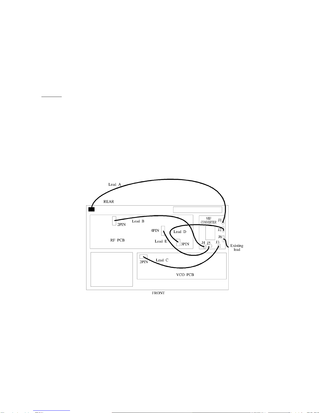
LEAD C
Connect lead “C” (short grey screened lead) between the vacant 2 pin connector of the
VCO PCB (see diagram) and J3 of the VHF converter.
LEAD E
Connect lead “E” (4 wire purple/white) between the vacant 4 pin connector of the RF PCB
(see diagram) and J5 of the VHF converter.
LEAD B
Connect lead “B” (Long grey screened lead with 2 pin connectors) between the vacant
2 pin connector of the RF PCB (see diagram) and J4 of the VHF converter.
LEAD A
Connect lead “A” (coaxial cable with one end un-terminated) using the miniature coaxial
connection to J1 of the VHF converter. Feed the un-terminated end through the rear left
hand corner of the chassis into the bottom cabinet.
Turn the set upside down and solder the coaxial cable to the currently unused VHF BNC
connector. The centre connector being soldered to the centre pin and the outer braid to
the earth of the BNC connector... there is no earth tag so solder to the BNC thread directly
(A VERY HOT SOLDERING IRON IS REQUIRED - BUT DON’T MELT THE COAX!).
Cable ties
Return the set to the right-way-up.
Cable tie together lead “A”, “B” & “D” just above the VHF converter toward the rear of the
cabinet. Keep lead “C” as far away from the other leads as possible running it high above
the PCBs.
Use a second cable tie about 10cm to the left, again strapping leads “A”, “B” & “D”
together.
The third cable tie is used to secure lead “C” high away from the input / output leads
leading to J4, J5 & J1.
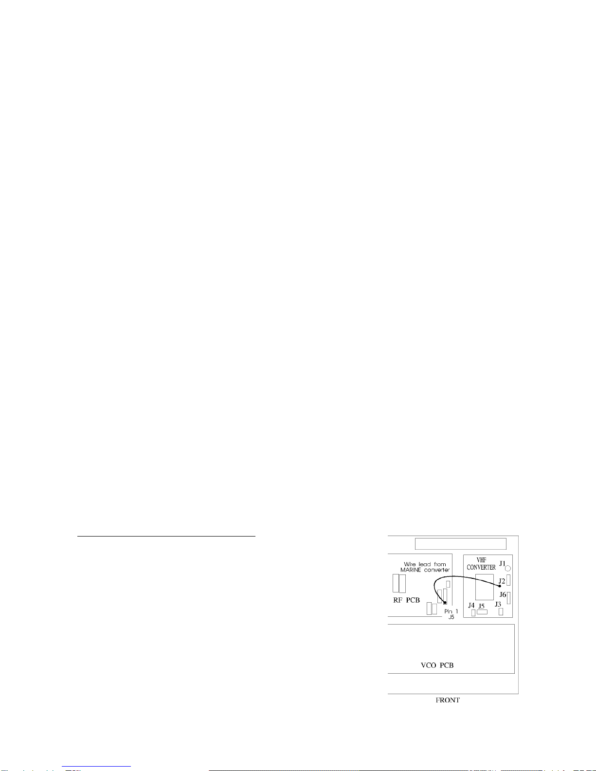
STEP 3A (MARINE converter only)
The MARINE converter requires an additional supply feed
which is taken from the RF PCB PIN 1 of J5 (refer to diagram
2). The MARINE converter has an additional flying lead
connected to the PCB.
For neatness carefully pull J5 of the RF PCB out of the socket
and remove the wire feeding PIN 1 (usually white), it is held
with a barb so lift the plastic retainer using a very small
screwdriver or pin. Neatly solder the flying lead from the
converter to the wire of Pin 1 and re-insert the connector into
the plug.
3/4