manuals.online logo
Brands
  1. Home
  2. •
  3. Brands
  4. •
  5. exaSound
  6. •
  7. Media Converter
  8. •
  9. exaSound e20 User manual

exaSound e20 User manual

e20 Digital to Analogue Converter
2 Channel PCM 32 bit / 384 kHz
DSD up to 256 Fs / 12.288 MHz
wner’s Manual (Windows)
PLEASE READ BEF RE PERATI N
REV. 1.0.3g – 03/2014
Page | 2
Table of Contents
Table of Contents .......................................................................................................... 2
Safety Information ....................................................................................................... 4
Explanation of Graphical Symbols ............................................................................................................ 4
Important Safety Instructions ................................................................................................................... 4
Precautions ............................................................................................................................................... 4
Welcome .......................................................................................................................... 7
Quick Start ...................................................................................................................... 8
Package Contents ...................................................................................................................................... 8
Proper Device Placement .......................................................................................................................... 8
Front Panel Controls ................................................................................................................................. 8
Rear Panel Connectors .............................................................................................................................. 9
Infrared Remote Control ........................................................................................................................... 9
Features ......................................................................................................................... 10
Windows ASI Driver Advantages ...................................................................................................... 10
Automatic Sampling Rate Switching ................................................................................................... 10
Automatic PCM / DSD Switching ......................................................................................................... 10
Bit-perfect operation independent from the Windows volume control and mixer ........................... 10
Asynchronous USB mode eliminates jitter caused by the PC or the USB interface ........................... 10
Connectin and Powerin the e20 DAC............................................................... 11
Connecting the Digital Inputs ................................................................................................................. 11
Connecting the Line utputs .................................................................................................................. 11
Direct Connection to Analogue Power Amplifier .................................................................................... 11
Analogue Interconnect Recommendations ............................................................................................ 12
Connecting the Power Adapter............................................................................................................... 12
Surge Protectors ..................................................................................................................................... 12
Isolating the Cable TV Ground ................................................................................................................ 12
Remote Control Setup ............................................................................................... 13
Windows Drivers Setup ............................................................................................ 14
Page | 3
PC System Requirements ........................................................................................................................ 14
Windows ASI Driver Installation ........................................................................................................... 14
Configuring Audio Player with ASI utput ........................................................................................... 16
Usin the e20 DAC ...................................................................................................... 17
Computer Playback Using the Asynchronous USB Input ........................................................................ 17
Volume Control ....................................................................................................................................... 18
Playing Music From SPDIF Sources ......................................................................................................... 19
Specifications ............................................................................................................... 20
Limited One Year Warranty .................................................................................... 23
Appendix A: J River Media Center Quick Start Guide ..................................... 25
Configure J River Media Center for Bit-perfect ASI Playback with the e20 DAC .................................. 30
Copyright © 2011-2014, exaSound Audio Design. All rights reserved.
Page | 4
Safety Information
Explanation of Graphical Symbols
The lightning flash with arrowhead symbol, within an equilateral triangle, is intended to
alert the user to the presence of uninsulated “dangerous voltage” within the product’s
enclosure that may be of sufficient magnitude to constitute a risk of electric shock to
persons.
The exclamation point within an equilateral triangle is intended to alert the user to the
presence of important operating and maintenance (servicing) instructions in the literature
accompanying the Device.
Important Safety Instructions
1. Read these instructions.
2. Keep these instructions.
3. Heed all warnings.
4. Follow all instructions.
5. Do not use this apparatus near water.
6. Clean only with dry cloth.
7. Do not block any ventilation openings. Install in accordance with the manufacturer’s instructions.
8. Do not install near any heat sources such as radiators, heat registers, stoves, or other apparatus
(including amplifiers) that produce heat.
9. Do not defeat the safety purpose of the polarized or grounding-type plug. A polarized plug has two
blades with one wider than the other. A grounding type plug has two blades and a third grounding
prong. The wide blade or the third prong is provided for your safety. If the provided plug does not fit
into your outlet, consult an electrician for replacement of the obsolete outlet.
10. Protect the power cord from being walked on or pinched, particularly at plug, receptacle, and the
point where it exits from the apparatus.
11. nly use attachments/accessories specified by the manufacturer.
12. Refer all servicing to qualified service personnel. Servicing is required when the device has been
damaged in any way, such as power-supply cord or plug is damaged, liquid has been spilled or
objects have fallen into the device, the device has been exposed to rain or moisture, does not
operate normally, or has been dropped.
Precautions
• Before connecting the AC power adapter cord to the device, make sure the voltage designation of
the power adapter corresponds to the local electrical supply. If you are unsure of your power
supply, contact your local power company. The acceptable power input range is AC ~ 100V-240V,
50/60Hz
• The device is still receiving power from the AC power source as long as it is connected to the wall
outlet, even if the device itself has been turned off.
Page | 5
• Unplug the power adapter if you are not going to use the device for an extended period of time.
Hold the power adapter when unplugging. Do not pull on the cord.
• The power adapter is used as the mechanism for cutting off power, therefore make sure it is easy to
unplug.
• To ensure proper ventilation around this product, do not place this product on a sofa, bed or rug.
• High temperature will lead to abnormal operation of this device. Do not expose this device or
batteries to direct sunlight or near heating objects.
• When moving the device from a cold location to a warm one, or vice versa, moisture may condense
on components inside the device. Should this occur, the device may not operate properly. In such a
case please turn the device off for 1-2 hours to facilitate moisture evaporation.
WARNING:
T REDUCE THE RISK F FIRE R ELECTRIC SH CK, D N T EXP SE THIS DEVICE T RAIN R M ISTURE.
DANGER US HIGH V LTAGES MAY BE PRESENT INSIDE THE ENCL SURE. D N T PEN THE CABINET. REFER
SERVICING T QUALIFIED PERS NNEL NLY. THE DEVICE SHALL N T BE EXP SED T DRIPPING R
SPLASHING AND THAT N BJECTS FILLED WITH LIQUIDS, SUCH AS VASES SHALL BE PLACED N THE
APPARATUS.
WARNING:
CHANGES R M DIFICATI NS N T AUTH RIZED BY THE MANUFACTURER CAN INVALIDATE THE
C MPLIANCE T REGULATI NS AND CAUSE THE UNIT T BE N M RE SUITABLE T USE. THE
MANUFACTURER REFUSES EVERY RESP NSIBILITY REGARDING DAMAGES T PE PLE R THINGS DUE T THE
USE F A UNIT WHICH HAS BEEN SUBJECT T UNAUTH RIZED M DIFICATI NS R T MISUSE R T
MALFUNCTI N F A UNIT WHICH HAS BEEN SUBJECT T UNAUTH RIZED M DIFICATI NS.
FCC
Statement
This equipment has been tested and found to comply with the limits for a Class B digital device,
pursuant to Part 15 of the FCC Rules. These limits are designed to provide reasonable protection
against harmful interference in a residential installation. This equipment generates, uses, and can
radiate radio frequency energy and, if not installed and used in accordance with the instructions,
may cause harmful interference to radio communications. However, there is no guarantee that
interference will not occur in a particular installation. If this equipment does cause harmful
interference to radio or television reception, which can be determined by turning the equipment
off and on, the user is encouraged to try to correct the interference by one or more of the
following measures:
• Reorient or relocate the receiving antenna.
• Increase the separation between the equipment and receiver.
• Consult the dealer or an experienced radio/TV technician for help.
Any unauthorized changes or modifications to this equipment would void the user’s authority to
operate this device. This device complies with Part 15 of the FCC Rules. peration is subject to the
following two conditions: (1) This device may not cause harmful interference, and (2) this device
must accept any interference received, including interference that may cause undesired operation.
This unit is compliant with the following CE regulations when an USB cable less than 3m is used:
CEI EN 55022:2009 Class B (Radiated Emissions), CEI EN 55024:1999, CEI EN 55024:A2/2003, CEI EN
55024:IS1/2008 (Radio Frequency Electromagnetic Fields, 50Hz Magnetic Field Immunity Test and
Electrostatic Discharges – ESD).
Page | 6
This product, when no longer usable, when disposed off can’t be treated as generic garbage, but
must be disposed of at a collection point for recycling of electrical and electronic equipment, in
compliance with the WEEE regulation (Waste of Electrical and Electronic Equipment).
By making sure that this unit is correctly recycled, you will help preventing potential damages to
environment and human health, which could be caused by the incorrect treatment of this product
as generic garbage. Materials recycling helps conserve natural resources.
We use our best efforts to ensure that information in this document is complete, accurate and
current, but otherwise we make no representation concerning the same. We reserve the right to
change or modify the information any time, without prior advice. It’s up to the customer to ensure
that the manual being consulted is the latest version.
Trade
marks
 Direct Stream Digital (DSD) is a trademark of Sony Corporation.
 Designed for Windows Media, Microsoft, HDCD, and the HDCD logo are trademarks or
registered trademarks of Microsoft Corporation in the United States and/or other countries.
 Apple, Mac and S X are trademarks of Apple, Inc.
 All other trademarks are the properties of their respective owners.
Page | 7
Welcome
Thank you for purchasing the exaSound e20 DAC!
The e20 Mk II is the first high-end DAC capable of achieving DSD playback at sampling rate of 11.2896
MHz. e20 Mk III introduces another first - DSD 256 Fs at 12.2888 MHz.
In addition to offering the highest digital audio resolution, the e20 DAC has jitter, distortion and noise
levels that are vanishingly low, creating an astonishingly clean and analog-like sound.
We hope that the e20 DAC will help you to enjoy world-class music experience for years to come. Please
take a few minutes to read right through this manual. Investing a little time now is the best way to
ensure that you make the most of your investment.
Your satisfaction is our highest priority.
Happy listening,
exaSound Audio Design
www.exaSound.com
CustomerService@exaSound.com
Page | 8
Quick Start
Packa e Contents
The following items should be in the box:
• e20 DAC
• Power supply
• Mini A-B USB cable
• IR Remote Control
Proper Device Placement
Place the device on a stable solid base, far from heat sources. Do not expose the device to direct
sunlight. Allow at least 2.5 cm (1'') around the device for ventilation. Do not place the device on fabrics,
inside enclosed space, or in contact with curtains. Do not place the device on top of power amplifiers or
any other equipment that emits heat. Do not expose the unit to smoke, humidity, moisture and water.
Keep the length of analogue interconnects and speaker cables short for optimal sonic performance.
Remember that cables act as filters. Shorter cables have less impact on sonic performance. The shorter
the cables, the more transparent they become.
Front Panel Controls
Headphones accepts a standard 1/4-inch stereo single-ended phone plug. Use a suitable
adapter for headphones equipped with a different plug.
Volume
Up
Setup
Volume
Down
Input
Select
Power Button
Headphones
Display
IR
Remote
Sensor
Page | 9
Rear Panel Connectors
SPDIF IN1
-
Coaxial SP
DIF Input
SPDIF IN2 - ptical T SLINK SPDIF Input
DC 12V / 0.8A - Power Adapter Connector
USB - Mini USB connector
RCA
Line Outputs
Left / Right
Analogue utputs
XLR Line Outputs Balanced
Left / Right Analogue utputs
Infrared Remote Control
Your unit is pre-programmed to work with the supplied remote control.
The e20 DAC can be re-programmed to work with most infrared remote controls using Sony and NEC IR
protocols, for example the Sony RM-EZ4 Universal Remote, or the Apple Remote Control.
See the Remote Control Setup section for instructions on how to change button assignments and how
to pair a different remote control with your e20 DAC.
XLR Line
Outputs
Optical
SPDIF I 2
Coaxial
SPDIF I 1
Power Adapter
Connector
USB
I
Volume
Up
Previous Input
Volume
Down
ext Input
Mute
Power
Volume
Up
Volume
Down
Mute
Power
ext Input
Previous Input
RCA Line
Outputs
XLR Line
Outputs
Page | 10
Features
The e20 DAC is based on the ES9018 Sabre
32
reference DAC chip. It delivers 32-bit precision capable of
resolving the smallest signal details. The chip features patented 32-bit Hyperstream™ architecture and
Time Domain Jitter Eliminator. ES9018 delivers the industry’s highest performance levels that will
satisfy the most demanding audio enthusiasts.
Windows ASIO Driver Advantages
Using ASI brings unique advantages that are hard to achieve and reliably verify with other Windows
driver technologies.
Automati Sampling Rate Swit hing
PCM data is always streamed without re-sampling. Native Windows 7 drivers often require manual
sampling rate selection and may apply implicit re-sampling when the source rate differs from the rate
set in the Windows Control Panel.
Automati PCM / DSD Swit hing
Audio data is always streamed in its native format. e20 switches automatically between PCM and DSD
modes. DSD streams are processed in their native format without conversion to PCM.
Bit-perfe t operation independent from the Windows volume ontrol and mixer
The Windows volume control and mixer are optimized to provide wide compatibility and easiness of
use. These features come at the expense of sound quality. The resulting output is not bit-perfect or bit-
transparent. Third party proprietary Windows drivers are hard to be verified as bit-perfect because
factors beyond the control of the user can change the Windows sound processing chain.
ur proprietary ASI implementation is completely independent from the Windows sound system and
always operates in Exclusive Mode. nly one player can take control of the ASI driver. When playback
starts the player sets the driver sampling rate to be the same as the native rate of the current media file.
The sound data stream is delivered to the e20 FIF memory buffer without any processing or
manipulation.
Asyn hronous USB mode eliminates jitter aused by the PC or the USB interfa e
Asynchronous USB is a two-way communication method between a computer and an external USB
device. In this method, the USB device is running as a master, and the computer is acting as a slave that
delivers data only when requested by the master.
In the case of the e20 DAC, sound data is requested by the FPGA core and stored in the device FIF
memory buffer. The FPGA core makes sure that the buffer never gets empty during playback. Data from
the buffer is streamed to the DAC chip. The precision of the timing of the output stream is determined
only by the DAC oscillators and it is not degraded in any way by the PC clocks or by delays caused by the
USB interface.
Page | 11
Connectin and Powerin the e20 DAC
Before connecting, turn off the power to all the components in your system.
Connectin the Di ital Inputs
All digital inputs are galvanically isolated to eliminate ground loop noise. The e20 DAC accepts three
digital inputs
• USB - This is the recommended and most capable input. It supports 2 channels PCM up to 32 bit
resolution at standard sampling frequencies from 44.1 kHz to 384 kHz, and DSD from 2.8224
MHz to 12.288 MHz (e20 MK III).
Connect the e20 DAC to your computer using the supplied Mini A-B USB cable. Most standard
Mini A-B USB cables with length up to 6 ft (2m) can be used.
• SPDIF IN1 - SPDIF Input, 75-ohm RCA. Supports 2 channels PCM up to 24 bit resolution at
standard sampling frequencies from 44.1 kHz to 192 kHz.
• SPDIF IN2 - SPDIF Input, T SLINK, ptical. Supports 2 channels PCM up to 24 bit resolution at
standard sampling frequencies from 44.1 kHz to 96 kHz.
Connectin the Line Outputs
The e20 DAC offers two types of analogue line outputs - unbalanced (RCA) and balanced (XLR).
• Make sure that your analogue power amplifier is turned off.
• RCA Line Outputs Left / Right - Connect the Left and Right RCA line outputs of the e20 DAC to
the amplifier line inputs.
or
• XLR Line Outputs Left / Right - Connect the Left and Right XLR line outputs of the e20 DAC to
the amplifier line inputs.
Direct Connection to Analo ue Power Amplifier
If your music sources are digital, you don't need a preamplifier. The built-in volume control allows
analogue power amplifiers to be connected directly to the e20 DAC. Amplification always brings some
level of noise and distortion. Eliminating unnecessary amplification helps to achieve higher level of
transparency.
Avoid connecting the
e20
DAC to receivers and any other sound processing equipment
that performs analogue to digital (ADC) conversion. Digitizing the analogue output signals
back to the digital domain for processing will undo the benefits that e20 brings to you.
Remember that your sound system is as good as the weakest link in the sound processing
chain.
Page | 12
Analo ue Interconnect Recommendations
ver-engineered interconnects made from exotic materials are unnecessary. When selecting cables, the
following characteristics are important:
• Reliable electrical contact
• Low resistance
• Robust mechanical design
Remember that cables act as filters. The shorter the cable, the more transparent your system will be.
Connectin the Power Adapter
To minimize ground noise and hum, it is recommended to connect the power cords of all components to
a single point - usually a single surge protector with multiple outlets. Connecting all components to a
single point, as close as it is practically possible minimizes the differences in ground potentials between
the components.
Using an Upgraded Power Supply
The e20 DAC comes with a 12V/1200mA power adapter. This power adapter has been
tested to comply with the DAC’s power supply and quality requirements and allows for
very high performance. A better unit may allow you to squeeze the last bit of performance
from the e20 DAC. Please be advised that using a different power supply than the one
included in the package may void the warranty.
If you decide to use another power supply, the specifications marked on the back of the
e20 DAC must be observed.
Sur e Protectors
We strongly recommend the use of surge protectors for all of your audio and video components.
Isolatin the Cable TV Ground
If you have a cable TV connected to your audio system, ensure that the TV cable ground is galvanically
isolated from the audio system ground. The TV cable ground, usually connected to the earth outside
your home, can have a significantly different potential than the audio ground. This condition can cause
audible hum. If you suspect this is the case, use a cable TV ground isolator just before the cable set-top
box or at the RF TV input.
When turning on and off your music system, the power amplifier should be the last
component to be turned on and the first component to be turned off. This prevents power
on/off transients from being transmitted to the loudspeakers.
Page | 13
Remote Control Setup
The e20 DAC is pre-programmed to work with the supplied remote control. If you like, you can
reprogram the e20 DAC to work with a different IR remote control. The exaSound e20 DAC can be
trained to recognise commands from most infrared remote controls using Sony and NEC IR protocols.
Use the following procedure to change remote control button assignments or to pair the e20 DAC with a
different remote control:
1.
Power on the
e20
DAC. Make sure that the unit is not in
playback mode.
2. Press the Setup button.
3.
Press the
Volume Up
button to conf
i
rm the remote control
programming mode, or press the Volume Down button to
cancel the operation.
4.
Point the remote control to the
e20
DAC display.
P
ress and hold
down the remote control buttons for about one second during
each step below to assign functions to them.
5. Press the remote control button for increasing the volume.
6.
Press the remote control button
for
decreasing
the volume
.
7.
Press the remote control button
for
selecting the next
input
.
8.
Press the remote control button
for
previous input
.
9.
Press the remote control button
for turning the unit on and off
.
10.
Press the remote control button
for
mute
.
11.
Wait until the remote control configuration is saved. Your
e20
DAC is now paired for use with the new IR remote control.
Page | 14
Windows Drivers Setup
PC System Requirements
• perating systems:
o Windows 8 x86 or Windows 8 x64
o Windows 7, 32 or 64 bit
o Windows XP / 32 bit with the latest service packs installed
• USB 2.0 / USB 3.0 interface
• 2 GB of RAM
• 10 GB disk space, mainly for music files
Windows ASIO Driver Installation
The first step required in the Windows setup process is to install the exaSound ASI driver:
1. Don’t connect the e20 DAC to the PC until the driver is installed. Don’t worry if you’ve connected the
device already. Just disconnect it.
2. Download the latest driver.
You should have received an email from us with username and password. Please login to our
support website at http://support.exasound.com/Downloads.aspx and download the latest version
of the exaSound G3 Windows ASI Driver. Don't use setup packages downloaded from other
websites.
3. Unzip the installation package and double-click on Install.exe to start the installation. Follow the
instructions. In most cases you just need to accept the defaults on the following screens.
Page | 15
4. Connect the e20 DAC. You should see a pop-up message on the computer screen indicating that e20
DAC is successfully installed. Note that this message has a different appearance on Windows XP and
Windows 7. Windows 8 may not display the message at all.
5. Upon completion of the Windows ASI driver installation you will see the exaSound e20 Dashboard
Icon in the System Tray area next to the clock.
Page | 16
6. If you don't see it, right-click on the clock and select Customize Notification Icons from the menu.
7. Scroll down to the exaSound e20 Dashboard icon and from the dropdown select Show icon and
notifications. Click OK.
8. You should be able to see the exaSound e20 Dashboard icons at all times. The Icon changes to
indicate playback, and displays an exclamation mark when the USB cable is disconnected:
exaSound Dashboard
Stop
Icon
Play
Icon
USB
Cable Disconnected
Icon
9. Close all programs and reboot Windows. Some ASI players may not recognise the driver if you omit
this step. If you don't restart Windows you may get an error message: "Hardware not present".
Confi urin Audio Player with ASIO Output
You can use most ASI -enabled software to stream PCM audio to the e20 DAC. In our experience J River
Media Center and Foobar2000 provided the best performance and sound quality.
Appendix A provides for step by step instructions for installing and configuring J River Media Center for
ASI playback with the e20 DAC.
Foobar 2000 configuration instructions are available on the exaSound website.
Page | 17
Usin the e20 DAC
Computer Playback Usin the Asynchronous USB Input
Before turning your amplifiers ON, always he k the e20 DAC front panel to make sure
that the volume level is below -25dB.
• The e20 DAC can be controlled from the front panel buttons, using an IR remote control or from
the computer screen.
• Make sure that all cables are connected. Turn on the unit using the Power button on the front
panel of the remote control. The front panel display will light up. After powering on the USB
Input is selected by default.
• Click on the exaSound e20 Dashboard Icon in the System Tray area next to the clock.
• You will see the exaSound e20 Dashboard window.
Channel View Minimised View
• During playback the current sampling rate is displayed under the master volume slider.
• You can customize the channel labels: Select a label with the mouse and edit the channel title.
Press Enter to save or Cancel to undo the change.
• Use the arrow button between the right channel and the master volume to toggle between
Channel View and Minimised View.
• Use the X button in the top right corner to minimize the exaSound e20 Dashboard window.
Page | 18
Volume Control
The e20 DAC volume is controlled by the ES9018 DAC chip. It is completely independent from the
Windows software volume control and it preserves the maximum possible signal to noise ratio.
The volume level changes in steps of 0.5 dB. At first power on, the volume level is set to -40dB. When
the dashboard is closed it remembers the volume level settings.
Use the sliders on the exaSound e20 Dashboard window to control the volume for individual channels,
and the master volume. The sliders can be controlled in several ways:
• By left-clicking and dragging a slider
• By positioning the mouse cursor over a channel and turning the mouse wheel. When the mouse
cursor is rested over the channel area the background color changes to indicate that the channel
is active
• By selecting a channel with the mouse and using the Up and Down arrow keys on the keyboard
The master volume can also be controlled from the device front panel or using a remote control. When
the master volume level is changed, the value displayed on the exaSound e20 Dashboard and on the
device front panel display are synchronised.
Volume levels for individual channels can be controlled only from the exaSound e20 Dashboard.
The sound can be muted by clicking the Mute button under the master volume slider or by using the
remote control. Pressing or clicking Mute again restores the previous volume level. Pressing Volume Up
or Volume Down will cancel the mute state.
Make sure that your player application is configured to use the e20 DAC in ASI mode (See Appendix A
for step by step instructions for J River Media Center). Start playback. You will see the level indicators
moving and the current sampling rate displayed on the exaSound Dashboard. The e20 DAC front panel
display will indicate the stream format (PCM or DSD), the sampling rate and the master volume level.
Note: level indicators are inactive in DSD mode.
Page | 19
Playin Music From SPDIF Sources
The e20 DAC makes it possible to enjoy greatly improved level of sonic clarity and fidelity from SPDIF
sources. The sonic improvement is the result of the outstanding jitter cancelling capability, superb signal
to noise ratio, and low distortion levels of the e20 DAC.
You can connect up to two SPDIF devices, such as disk players and wireless music servers.
To use SPDIF sour es:
1.
Select SPDIF input by pressing the
Input
button on the device front
panel or by using the Previous Input / Next Input buttons on the
remote control.
2.
The
e20
front panel
display will flash a
Changing Input
message.
3.
The
e20
front panel will display information about the input in use,
the current sampling rate, and the master volume level.
Page | 20
Specifications
D/A Co
nvert
er IC:
ESS Technology ES
9018S
Sabre
32
Reference DAC
PCM Sampling Rates -
Asynchronous USB ASI
44.1kHz, 48 kHz, 88.2 kHz, 96 kHz, 176.4 kHz, 192 kHz,
352.8 kHz, 384 kHz
DSD Sampling Rates -
Asynchronous USB ASI
e20 e20 Mk II e20 Mk III
DSD 64 Fs:
2.8224 MHz
DSD 128 Fs:
5.6448 MHz,
DSD 64 Fs:
2.8224 MHz
DSD 128 Fs:
5.6448 MHz
DSD 256 Fs:
11.2896 MHz
DSD 64 Fs:
2.8224 MHz
3.072 MHz
DSD 128 Fs:
5.6448 MHz
6.144 MHz
DSD 256 Fs:
11.2896 MHz
12.288 MHz
Sampling Rates
-
SPDIF Coaxial IN 1
PCM
44.1kHz, 48 kHz, 88.2 kHz
, 96 kHz, 176.4 kHz,
192 kHz
Sampling Rates
-
SDIF ptical
IN
2
PCM
44.1kHz, 48 kHz, 88.2 kHz,
96 kHz
To
tal Harmonic Distortion + Noise
0.0002%
@ 1KHz, 0dBFS
Intermodulation Distortion
-
142 dB /
0.0000079
% @ 19KHz + 20KHz 0 dBFS
2nd order IMD
Signal
-
to
-
Noise Ratio
128 dB,
A
-
weighted, 2
Vrms
DAC Master Clock Jitter
0.13
psec rms
Frequency Response
0 Hz
-
20 KHz (
-
0.15dB)
Phase
Non
-
inverting
Channel Separation
130 dB @ 1KHz
Digital Inputs
USB 2.0, SPDIF Coaxial, SP
DIF T SLINK (optical)

Other exaSound Media Converter manuals

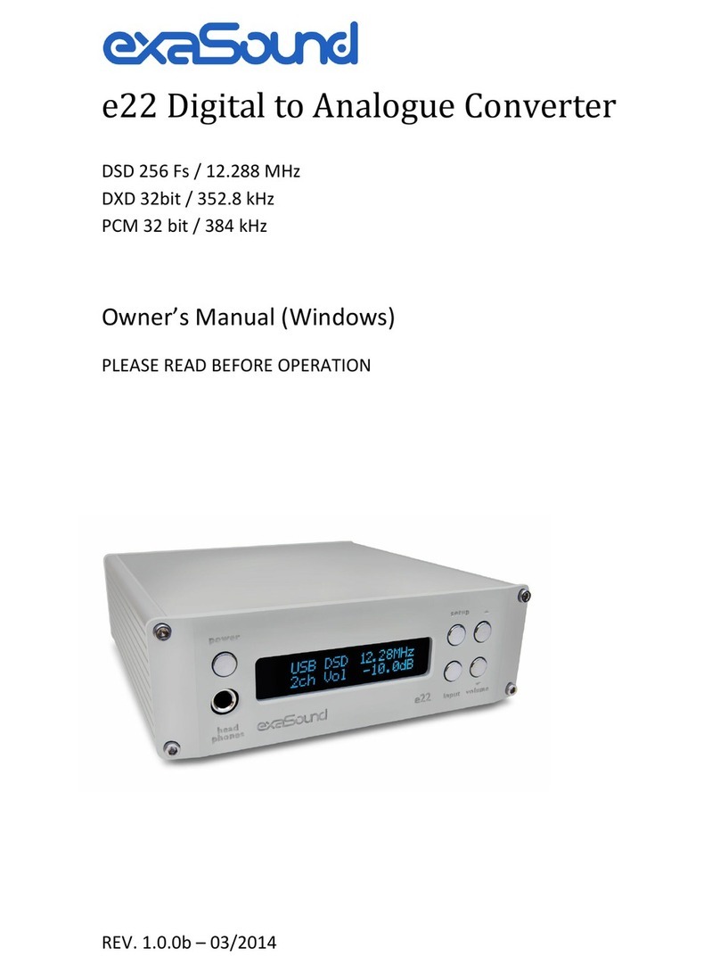
exaSound e68 User manual

exaSound

exaSound e68 User manual

exaSound e62 User manual

exaSound

exaSound e62 User manual

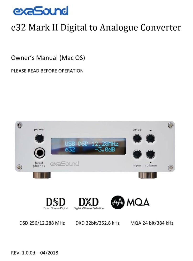
exaSound e32 Mark II User manual

exaSound

exaSound e32 Mark II User manual

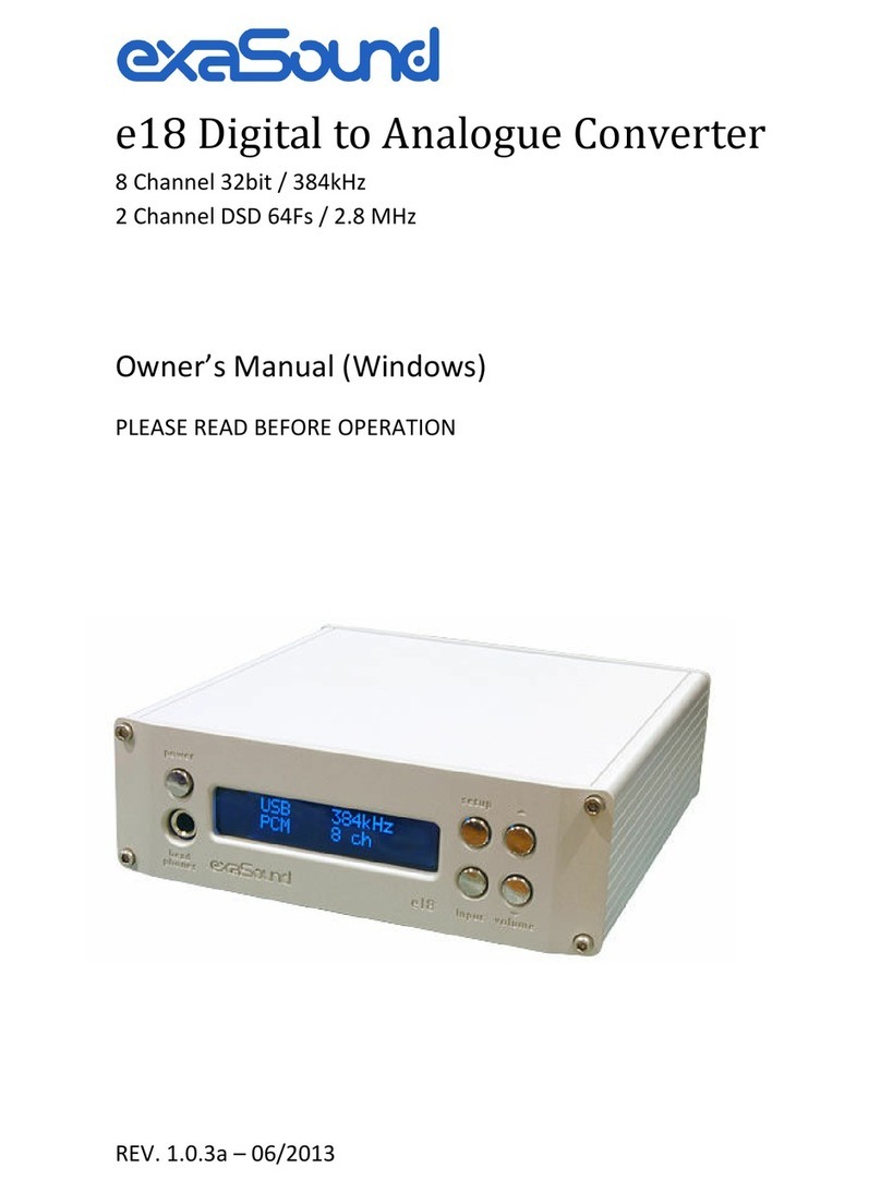
exaSound e18 User manual

exaSound

exaSound e18 User manual

exaSound e22 Mark II User manual

exaSound

exaSound e22 Mark II User manual

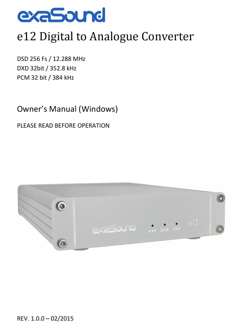
exaSound e12 DAC User manual

exaSound

exaSound e12 DAC User manual

exaSound e22 Mark II User manual

exaSound

exaSound e22 Mark II User manual

exaSound e12 DAC User manual

exaSound

exaSound e12 DAC User manual

exaSound e28 User manual

exaSound

exaSound e28 User manual

Popular Media Converter manuals by other brands

VigilLink VL-SP18-1 user manual

VigilLink

VigilLink VL-SP18-1 user manual

LevelOne VDS-0202 BNC user manual

LevelOne

LevelOne VDS-0202 BNC user manual

MuxLab Prodigital DisplayPort 1.2A Quick installation guide

MuxLab

MuxLab Prodigital DisplayPort 1.2A Quick installation guide

Siemens 7XV5662-0AC01 manual

Siemens

Siemens 7XV5662-0AC01 manual

CYP CSLUX-300 Operation manual

CYP

CYP CSLUX-300 Operation manual

Cross Technologies 3117-3338 720 Series instruction manual

Cross Technologies

Cross Technologies 3117-3338 720 Series instruction manual

Omnitron Systems Technology Fiber-to-Fiber Converter 1000FF user manual

Omnitron Systems Technology

Omnitron Systems Technology Fiber-to-Fiber Converter 1000FF user manual

ELECTROCOMPANIET ECD 2 owner's manual

ELECTROCOMPANIET

ELECTROCOMPANIET ECD 2 owner's manual

RSF Elektronik MSA 871 Mounting instructions

RSF Elektronik

RSF Elektronik MSA 871 Mounting instructions

Cerwin-Vega IOEM44 quick start guide

Cerwin-Vega

Cerwin-Vega IOEM44 quick start guide

CYP DCT-25 Operation manual

CYP

CYP DCT-25 Operation manual

Omron E6B2-C datasheet

Omron

Omron E6B2-C datasheet

I-Taki HIT-HD1080-2-4KW user manual

I-Taki

I-Taki HIT-HD1080-2-4KW user manual

LevelOne FVM-1101 user manual

LevelOne

LevelOne FVM-1101 user manual

Huahuan Electronics H0FL-EthMux.SA1601 user manual

Huahuan Electronics

Huahuan Electronics H0FL-EthMux.SA1601 user manual

OT Systems FT210AB Series Installation and operation manual

OT Systems

OT Systems FT210AB Series Installation and operation manual

moon 100 D owner's manual

moon

moon 100 D owner's manual

Extron electronics RGB to DVI Scaler RGB-DVI 300 user guide

Extron electronics

Extron electronics RGB to DVI Scaler RGB-DVI 300 user guide

manuals.online logo
manuals.online logoBrands
  • About & Mission
  • Contact us
  • Privacy Policy
  • Terms and Conditions

Copyright 2025 Manuals.Online. All Rights Reserved.