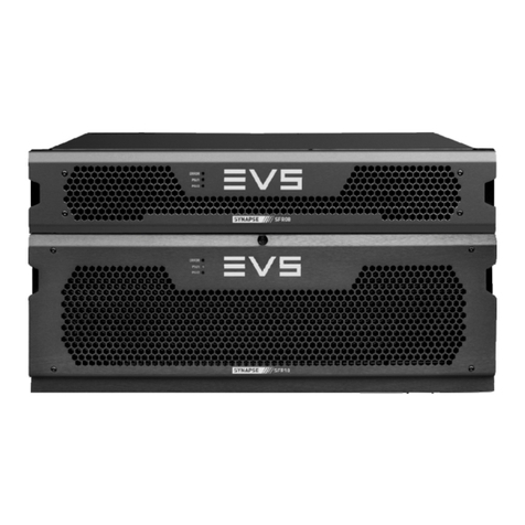
EVS GXG400 Instruction sheet

INSTALLATION &
CONFIGURATION
MANUAL
GXG400 – GXG410
3GB/S, HD AND SD UP/DOWN/CROSS
CONVERTER AND SYNCHRONIZER
WITH OPTIONAL AUDIO SHUFFLER

INSTALLATION AND CONFIGURATION MANUAL
GXG400
–
GXG410
Copyright
EVS Broadcast Equipment S.A. – Copyright © 2001 – 2021. All rights reserved.
Disclaimer
The information in this manual is furnished for informational use only and subject to change
without notice. While every effort has been made to ensure that the information contained in
this user manual is accurate, up-to-date and reliable, EVS Broadcast Equipment cannot be held
responsible for inaccuracies or errors that may appear in this publication.
Improvement Requests
Your comments will help us improve the quality of the user documentation. Do not hesitate to
send improvement requests, or report any error or inaccuracy on this user manual by e-mail to
Regional Contacts
The address and phone number of the EVS headquarters are usually mentioned in the Help >
About menu in the user interface.
You will find the full list of addresses and phone numbers of local offices either at the end of this
user manual (for manuals on hardware products) or on the EVS website on the following page:
http://www.evs.com/contacts.
User Manuals on EVS Website
The latest version of Media Infrastructure manuals are available at: https://mi-sftp.evs.com/
The user manuals for other EVS products can be found at the EVS download center, on the
following webpage: https://www.evs.com/en/download-area.

EVS Broadcast E
q
ui
p
ment SA
1
WARNING: TO REDUCE THE RISK OF FIRE OR
ELECTRICAL SHOCK, DO NOT EXPOSE THIS
APPLIANCE TO RAIN OR MOISTURE
●ALWAYS disconnect your entire system from the AC mains before cleaning any component. The product
frame (SFR18 or SFR04) must be terminated with three-conductor AC mains power cord that includes an
earth ground connection. To prevent shock hazard, all three connections must always be used.
●NEVER use flammable or combustible chemicals for cleaning components.
●NEVER operate this product if any cover is removed.
●NEVER wet the inside of this product with any liquid.
●NEVER pour or spill liquids directly onto this unit.
●NEVER block airflow through ventilation slots.
●NEVER bypass any fuse.
●NEVER replace any fuse with a value or type other than those specified.
●NEVER attempt to repair this product. If a problem occurs, contact your local EVS distributor.
●NEVER expose this product to extremely high or low temperatures.
●NEVER operate this product in an explosive atmosphere.
Warranty: EVS warrants their products according to the warranty policy as described in the general terms.
That means that EVS Broadcast Equipment SA can only warrant the products as long as the serial numbers
are not removed.
Copyright © 2001 – 2021 EVS Broadcast Equipment SA
Date created: 24-02-2015
Date last revised: 07-09-2015
EVS, the EVS logo and Synapse are trademarks of EVS Broadcast Equipment SA
This product complies with the requirements of the product family standards for audio, video, audio-visual
entertainment lighting control apparatus for professional use as mentioned below.
EN60950
EN55103-1: 1996
EN55103-2: 1996
Safety
Emission
Immunity
EVS Broadcast Equipment
GXG400 – GXG410
Tested To Comply
With FCC Standards
FOR HOME OR OFFICE USE
This device complies with part 15 of the FCC Rules
Operation is subject to the following two conditions:
(1) This device may cause harmful interference, and
(2) This device must accept any interference received, including
interference that may cause undesired operation.

INSTALLATION AND CONFIGURATION MANUAL
GXG400
–
GXG410
2
Index
Index 2
Introduction to Synapse 6
An Introduction to Synapse 6
Local Control Panel 6
Remote Control Capabilities 6
Unpacking and Placement 7
Unpacking 7
Placing the card 7
A Quick Start 8
When powering-up 8
Changing settings and parameters 8
Front Panel Control 8
Example of changing parameters using front panel control 9
EVS Cortex Software 10
Menu Structure Example 10
The GX400/GXG410 Card 11
Introduction 11
Features 11
Conversion capabilities 12
Applications 12
Block schematic 13
Important notice about closed captions 13
Settings Menu 14
Introduction 14
HDMI1-Format ~ HDMI2-Format 14
HDMI1-DVI-Mode ~ HDMI2-DVI-Mode 14
HDMI1-GrpA-Sel ~ HDMI2-GrpA-Sel 14
HDMI1-GrpB-Sel ~ HDMI2-GrpB-Sel 14
HDMI1-Mute-All ~ HDMI2-Mute-All 14
CVBS1-In-Format ~ CVBS4-In-Format 15
CVBS1-Input-Hue ~CVBS4-Input-Hue 15
IO-Ctrl 15
IO_Prst_Act 15
IO_Prst_Edit 15
PrstEditView 15
#Inp_SelA 15
#Out-FrmtA 16
#Output_Map_A 16
#4K_Map_A 16
#Out-Mode 16
#F-delayA 16
#V-delayA 17
#H-delayA 17
#Freeze_A 17
#HD_SD_LPF_A ~ #K4_down_LPF_A 17
#VANC_TransA 19
#VANC_Trans_Ln0A ~ #VANC_Trans_Ln5A 19
Pos-Prst_Act 19
Pos-Prst_edit 19
#H-Pos-A 19
#V-Pos-A 19
Lock-Mode 19
Delay-Status 19
Dolby-E-ModeA 19
PatternSpeed 20
WST-InsertA 20
S2031-OP47-DecA 20
S2031-OP47-EncA 20
S2031-EmbA 20
S2031-WST-DefA 20

EVS Broadcast E
q
ui
p
ment SA
3
OP47-SDP-Emb_A 20
SD_AR-Det 20
NoWSS/VI_prstA 21
Input_Loss_A 21
Up_CtrlA 21
Up_Prst_actA 21
UP_Prst_editA 21
#Up_ArcA 22
#Up_H-scaleA 22
#Up_V-scaleA 22
#Up_H-EnhA 22
#Up_V-EnhA 22
#Up_ColorConvA 22
Dn_CtrlA 23
Dn_Prst_actA 23
Dn_Prst_editA 23
#Dn_ArcA 23
#Dn_H-scaleA 24
#Dn_V-scaleA 24
#Dn_H-EnhA 24
#Dn_V-EnhA 24
# Dn_ColorConvA 24
Cr_CtrlA 24
Cr_Prst_actA 24
Cr_Prst_editA 25
#Cr_ArcA 25
#Cr_H-scaleA 25
#Cr_V-scaleA 25
#Cr_H-EnhA 26
#Cr_V-EnhA 26
Tr_CtrlA 26
Tr_Prst_ActA 26
Tr_Prst_EditA 26
#Tr_ArcA 26
#Tr_H-scaleA 26
#Tr_V-scaleA 27
#Tr_H-EnhA 27
#Tr_V-EnhA 27
Timecode_insA 27
VITC_Ln_InA 27
VITC_Ln_CtrlA 27
VITC_Ln_625A 27
VITC_Ln_525A 27
VITC_Ln_DupA 27
ATC_Dem_SelA 27
ATC_Emb_SelA 28
Ins_CtrlA 28
Ins_Prst_ActA 28
Ins_Prst_EditA 28
#VI-InsertA 28
#VI-DataA 28
#WSS-InsertA 28
#WSS-StndA 28
#WSS-ExtndA 28
#VI-DataA 29
#S2016-InsertA 29
#S2016-LineA 29
#S2016-DataA 29
#CC_Ena_A 29
GainA 29
R-GainA 29
G-GainA 29
B-GainA 29
BlackA 29
R-BlackA 29
G-BlackA 30
B-BlackA 30
Note 30
Y_Gain 30
C_Gain 30
Audio_CtrlA 30
Audio_Prst_ActA 30

INSTALLATION AND CONFIGURATION MANUAL
GXG400
–
GXG410
4
Audio_Prst_EditA 30
#Silence-TimeA 30
#Silence-LevelA 30
#Emb1_GrpSel 31
#Emb1_Ch01/04 31
#Emb1_Ch13/16 31
#Emb1_Gain01 ~ #Emb1_Gain16 32
#Emb1_Delay01 ~ #Emb1_Delay16 32
#Emb1_Phase01/16 32
Audio-PhaseA 32
IP_Conf0 33
mIP0 33
mNM0 33
mGW0 33
NetwPrefix0 33
Status Menu 34
Introduction 34
SFP1-Vendor 34
SFP1-Type 34
SFP1-Temp-Stat 34
SFP1-Volt-Stat 34
Port1/2-Enabled 34
Port1/2-Power 34
Port1/2-Power-Stat 34
Port1/2-Bias 34
Port1/2-Bias-Stat 34
Port1/2-Wavelength 35
SFP2-Vendor 35
SFP2-Type 35
SFP2-Temp-Stat 35
SFP2-Volt-Stat 35
Port3/4-Enabled 35
Port3/4-Power 35
Port3/4-Power-Stat 35
Port3/4-Bias 35
Port3/4-Bias-Stat 35
Port3/4-Wavelength 35
HDMI1-Vid-Std ~ HDMI2-Vid-Std 36
HDMI1-GrpInUse ~ HDMI2-GrpInUse 36
HDMI1-EDH-Stat ~ HDMI2-EDH-Stat 36
sInp1 ~ sInp2 36
sInpA 36
sInpA_VI 37
sInpA_WSS-Stnd 37
sInpA_WSS-Extd 38
sInpA_S2016 38
sInpA_CRC_EDH 38
sInpA_Map 38
sInpA_VITC 38
sInpA_ATC 39
S2031-WST-DetA 39
S2031-OverflowA 39
S2031-WST-LineA 39
WST-DetA 39
OP47-Det-A 39
CC_Det_A 39
IODelayA 39
FunctionA 40
Ref-Format 40
GPI 40
GPIA 40
GPIB 40
GPIC 40
SDIADemFrmt01/02 ~ SDIADemFrmt15/16 40
EmbStat_A 41
AddOnFrmtInA1/2 ~ AddOnFrmtInD3/D4 41
AddOnFrmtIn01/02 ~ AddOnFrmtIn31/32 41
SOF-E_A1/2A ~ SOF-E_D3/4A 41
FPGA_Core_Temp 41

EVS Broadcast E
q
ui
p
ment SA
5
IP_Addr0 41
MAC0 42
IP0 42
NM0 42
GW0 42
Events Menu 43
Introduction 43
What is the Goal of an event? 43
Events 43
Announcements 43
Input_A 43
Input_B 43
Ref-Status 43
Active_Out_A 43
What information is available in an event? 43
The Message String 44
The Tag 44
Defining Tags 44
The Priority 44
The Address 44
LED Indication 45
Error LED 45
Input_x LED 45
ANC Data LED 45
Reference LED 45
Data Error LED 45
Connection LED 45
Block Schematic 46
Connector Panels 47
Appendix 1 48
GPI Interface 48
Appendix 2 49
Reprogramming GXGxxx modules 49
Before you start 49
Functionality explanation 49
Choosing .spf files 49
Requirements 49
Using Cortex help files 49
Precautions 50
Backup your settings 50
At your own risk 50
Setting up card 51
Testing 53
GNU Public License version 2 54

INSTALLATION AND CONFIGURATION MANUAL
GXG400
–
GXG410
6
1 Introduction to Synapse
An Introduction
to Synapse
Synapse is a modular system designed for the broadcast industry. High
density, intuitive operation and high quality processing are key features
of this system. Synapse offers a full range of converters and processing
modules. Please visit the EVS Broadcast Equipment SA Website at
http://www.evs.com to obtain the latest information on our new
products and updates.
Local Control
Panel
The local control panel gives access to all adjustable parameters and
provides status information for any of the cards in the Synapse frame,
including the Synapse rack controller. The local control panel is also
used to back-up and restore card settings. Please refer to the rack
controller manuals for a detailed description of the local control panel,
the way to set-up remote control over IP and for frame related settings
and status information.
Remote Control
Capabilities
The remote control options are explained in the rack controller (RRC,
RRS, ERC or ERS) manual. The method of connecting to a computer
using Ethernet is also described in these manuals.
! CHECK-OUT: “EVS CORTEX” SOFTWARE WILL
INCREASE SYSTEM FLEXIBILITY OF ONE OR MORE
SYNAPSE FRAMES
Although not required to use Cortex with a Synapse frame, you are
strongly advised to use a remote personal computer or laptop PC with
EVS Cortex installed, as this increases the ease of use and
understandin
g
of the modules.

EVS Broadcast E
q
ui
p
ment SA
7
2 Unpacking and Placement
Unpacking The EVS Synapse card must be unpacked in an anti-static environment.
Care must be taken NOT to touch components on the card – always
handle the card carefully by the edges. The card must be stored and
shipped in anti-static packaging. Ensuring that these precautions are
followed will prevent premature failure from components mounted on
the board.
Placing the card The Synapse card can be placed vertically in an SFR18 frame or
horizontally in an SFR04, SFR08 and SFR Mobile frame. Locate the
two guide slots to be used, slide in the mounted circuit board, and push
it firmly to locate the connectors.
Correct insertion of card is essential as a card that is not located
properl
y
ma
y
show valid indicators, but does not function correctl
y
.
Note On power up all LED’s will light for a few seconds,
this is the time it takes to initialise the card

INSTALLATION AND CONFIGURATION MANUAL
GXG400
–
GXG410
8
3 A Quick Start
When powering-
up
On powering up the Synapse frame, the card set will use basic data and
default initialisation settings. All LED’s will light during this process.
After initialisation, several LED’s will remain lit – the exact number
and configuration is dependent upon the number of inputs connected
and the status of the inputs.
Changing
settings and
parameters
The front panel controls or the Synapse Cortex can be used to change
settings. An overview of the settings can be found in chapter 5, 6 and 7
of this manual.
Front Panel
Control
Front Panel Display and Cursor
Settings are displayed and changed as follows;
Use the cursor ‘arrows’ on the front panel to select the menu and
parameter to be displayed and/or changed.
Press ►To
g
o forward throu
g
h the menu structure.
Press ◄To
g
o back throu
g
h the menu structure.
Press ▲To move up within a menu or increase the value of
a parameter.
Press ▼To move down through a menu or decrease the
value of a parameter.
Note Whilst editing a setting, pressing ►twice will reset
the value to its default
[No Alarms]

EVS Broadcast E
q
ui
p
ment SA
9
Example of
changing
parameters
using front
panel control
With the display as shown below
Pressing the ►selects the SFS10 in frame slot 01.
The display changes to indicate that the SFS10 has been selected. In this
example the Settings menu item is indicated.
Pressing the ►selects the menu item shown, in this example
Settings.
(Pressing ▲or ▼will change to a different menu eg Status,
Events).
The display changes to indicate that the SFS10 Settings menu item
SDI-Format has been selected and shows that it current setting is
Auto.
Pressing the ►selects the settings item shown, in this example SDI-
Format.
(Pressing ▲or ▼will change to a different setting, eg Mode, H-
Delay).
The display changes to indicate that the SFS10 Edit Setting menu
item SDI-Format has been selected.
To edit the setting of the menu item press ▲or ▼.
All menu items can be monitored and/or changed in this way. Changing
a settin
g
has an immediate effect.
RRC18 [Select Card]
>S01=SFS10
SFS10 [Select Menu]
>Settings
SFS10 [Settings]
>SDI-Format=Auto
SFS10 Edit Setting]
SDI-Format>Auto

INSTALLATION AND CONFIGURATION MANUAL
GXG400
–
GXG410
10
EVS Cortex
Software
Synapse Cortex can be used to change the settings of Synapse modules
from a PC, either locally or remotely. The software enables
communication based on TCP/IP between the Setup PC and Synapse
frames/modules.
Each Synapse frame is addressed through its rack controller’s unique IP
address, giving access to each module, its menus and adjustment items.
EVS Cortex has access to data contained within the Synapse module
and displays it on a GUI. The software has an intuitive structure
following that of the module that it is controlling.
For operation of EVS Cortex, please refer to the Cortex help files.
Menu Structure
Example
Slot Module Item Paramete
r
Settin
g
▲
▲
S02 Identit
y
▲▲
S01 SFS10
►Set-
tings
►
Standard_dig ►Auto
▼▼▼▼
S00 RRC18 Status Mode 625
▼▼▼
Events Ref-Input 525
▼
H-Delay
▼
▼
Note Further information about Front Panel Control and
Synapse Cortex can be obtained from the RRC, RRS,
ERC and ERS operational manuals and the Cortex
help files

EVS Broadcast E
q
ui
p
ment SA
11
4 The GX400/GXG410 Card
Introduction The GXG400/410 is a high end up/down/cross converter. Based on
EVS's Motion Optimized Quality De-interlacer (MOQD), and
extensively computer optimized scaling and filter algorithms the new
400 series of up/down/cross converters ensure the absolute best quality
video conversion from any standard to any standard within the same
framerate. The card allows you to simulcast any output standard in any
format from any source standard.
The embedded audio is carried over to the SD, HD or 3Gb/s domain.
The appropriate aspect ratio can be applied by control of VI, WSS and
GPI inputs by use of 16 presets per output that can store the aspect
ratio conversions.
Beside a high quality up/down/cross converter, these cards also have
very powerful audio shufflers and proc-amps (410 only). Any of the 64
audio source channels (16 from SDI 1, and 32 from the quad speed
audio bus) can be routed to any of the 48 output channels (16 to SDI
output 1 and 32 to the quad speed audio bus)
Features
Industry highest quality de-interlacing algorithm using EVS's
MOQD
3Gb/s signals level A and level B compatible
Compatible with the following formats
1080p/59.94
1080p/50
1080i/59.94
1080i/50
1080p/29.97
1080p
/
25
720p/59.94
720p/50
SD525
SD625
Regardless of the conversion, every conversion will have a constant
latency.
Multiple external Inputs and Outputs
4 SDI inputs and outputs
Up to 4 optional extra inputs/outputs by use of 2 SFP cages
(fiber or coaxial, CVBS and HDMI)
10Gb/s Ethernet connection for future use of Ethernet based
video like AVB
7 configurable GPI I/O contacts
Ethernet for control
LTC and Metadata input
Frame synchronizer with auto-phaser and control in Frames, Lines
and pixels with respect to reference.
All ARC modes contain Anamorphic, Center Cut, V-Zoom, LBox-
16:9, LBox-14:9, PBox-4:3, PBox-14:9 and Variable H and V (50-
200%)

INSTALLATION AND CONFIGURATION MANUAL
GXG400
–
GXG410
12
16 free individual programmable preset banks with settings for:
Down conversion, Up conversion and Cross conversion
Transparent pass through (with ARC function)
Simultaneous VI, WSS and AFD (S2016) insertion
Embedder shuffling, gain and phase (in GXG410 only)
audio delay setting (in GXG410 only)
ARC triggers by VI, WSS, WSS-ext and S2016 (AFD)
Transparent for 16 channels of embedded audio per video channel
Embedded domain 64x64 routing to and from the individual
in/outputs and Quad Speed Audio Bus (410 only)
Video proc-amp (Y and C control)
Color corrector (RGB and total gain, RGB and total black)
Medium latency conversion process (2 frames)
Quad Speed Embedding and de-embedding through synapse bus
Locks to Tri-level, Bi-level or SDI input 1 or 2
Full control and status monitoring through the front panel of the
SFR04/SFR08/SFR18 frame and the Ethernet port (ACP)
Conversion
capabilities
Output
CONVERSION
2160p59.94
2160p50
1080p59.94
1080p50
1080p29.97
1080p25
1080i59.94
1080i50
720p59.94
720p50
720p29.97
720p25
480i59.94(52
5)
576i50(625)
SDII Input
2160p59.94 x x x x*x*x*
2160p50 x x x x*x*x*
HDMI Input
1080p59.94 x x x x x x x
1080p50 x x x x x x x
1080p29.97 x x x x x x x
1080p25 x x x x x x x
1080i59.94 x x x x x x x
1080i50 x x x x x x x
720p59.94 x x x x x x x
720p50 x x x x x x x
720p29.97 x x x x x x x
720p25 x x x x x x x
480i59.94(525) x x x x x x x
576i50(625) x x x x x x x
CVBS
480i59.94(NTSC) x x x x x x x
576i50(PAL) x x x x x x x
Applications High End Truck frame synchronizer and anything to anything
converter
High End Infrastructure up/down/cross conversion
High End transmission up/cross conversion

EVS Broadcast E
q
ui
p
ment SA
13
Block schematic
INT ER NAL SYN APS E BU S
GXG400 – GXG410
[QUAD SPEED AUIO BUS]
RACK
CONTROLLER
REFERENCE
INPUTS
12
µP [L INUX]
CHANNEL A
MOQ D
UP/DOWN/CRO SS
- ARC - BYPASS -
PLL
WSS-V I-S201 6
DETECTION
EQ
EQ
3Gb/s. HD, SD OUT 2
3Gb/s, HD, SD OUT 4
DUAL CHANNEL SFP
4X10
16 CH (TOP LEFT)
DE-EMBE DDING
EMBE D
16 CH
WSS-VI-S2016
VANC FORMAT
INSERT
16 CHANNEL
GAIN, DELA Y PHASE
(GXG410 ONLY)
QUAD SPEED
MULTIPLEXING
AUDI O BUS
32CH
OUT
32CH
IN
TO ADD -ON
FROM A DD-ON
FRAME SYNC,
2s 3Gb/s
OFFSE T DELAY,
C OL O R CO RR .
LEFT
TOP
SCALER
TDM
MUX
TDM
DE-MUX
DUAL CHANNEL SFP
VANC DECODING
AUDIO ROUTING: PRESET BASED
48X48 A UD IO MUX (GXG410 ONLY)
SFP+
EQ
EQ
OPTIONAL
DUAL 10G-
ETHERNET
FOR F UTURE
USE
S2022/AVB
RIGHT
TOP
SCALER
LEFT
BOTTOM
SCALER
RIGHT
BOTTOM
SCALER
10X4
384 0 X 216 0
TO
192 0 X 108 0
4 QUA DRANT
SCALER
SFP+
Important
notice about
closed captions
Historically, closed captions were transmitted in NTSC line 21 according to EIA-
CEA-608-B (bit rate 960b/s). This allowed two caption data bytes per field to be
transmitted. With the introduction of HD and 3Gb/s the new EIA-708-B Closed
Caption standard was created, which sends closed caption data in DTVCC packets.
This allows sending more data per field (bit rate 9600b/s) for extended language,
color support, PMT and EIT and timecode data.
Besides the new DTVCC packets, the EIA-708-B caption stream may also include
EIA-CEA-608-B data bytes which are stored as NTSC compatibility bytes for
compatibility with old decoders.
EIA-CEA-608-B Transparency
This card is fully transparent to EIA-CEA-608-B caption streams.
EIA-CEA-608-B to EIA-708-B Translation
For EIA-CEA-608-B to EIA-708-B translation, the EIA-CEA-608-B bytes will be
mapped on-one-on to the NTSC compatibility bytes. Furthermore, the EIA-CEA-608-
B bytes will be remapped to DTVCC packets.
EIA-708-B to EIA-CEA-608-B Translations
There are EIA-708-B DTVCC captions which are not translatable to EIA-CEA-608-
B. Therefore the NTSC compatibility bytes will be used for EIA-708-B to EIA-CEA-
608-B translation. So the DTVCC packets from the input will be ignored.
EIA-708-B Transparency
This card is not fully transparent to EIA-708-B caption streams. The NTSC
compatibility bytes are transparent, but the DTVCC packets are regenerated from the
NTSC compatibility bytes. So the DTVCC packets from the input will be ignored.
Note for EIA-708-B DTVCC output caption data:
Only supports EIA-CEA-608-B translation of the primary language (CC1). So CC2
to CC4, T1 to T4 and XDS translations are not supported.

INSTALLATION AND CONFIGURATION MANUAL
GXG400
–
GXG410
14
5 Settings Menu
Introduction The settings menu displays the current state of each GXG4x0 setting
and allows you to change or adjust it. Settings can be changed using
the front panel of the Synapse frame (SFR18, SFR08 or SFR04) or
with Cortex. Also the SCP08 control can be used. Please refer to
chapter 3 for information on the Synapse front panel control and
Cortex.
Note: All items preceded with a #-si
g
n are part of the presets.
HDMI
HDMI1-Format ~
HDMI2-Format Here you select the output format of the corresponding HDMI output
module. Possible modes are
■RGB444 (default)
■YCrCb422
■YCrCb444
HDMI1-DVI-Mode
~ HDMI2-DVI-
Mode
With these settings you set the corresponding HDMI output to either
DVI-Mode or HDMI-Mode. Default is DVI-Mode.
HDMI1-GrpA-Sel ~
HDMI2-GrpA-Sel The HDMI outputs can contain 2 groups of audio. Here you select
which input group should be in group A of the corresponding HDMI
output. Can be
g
roup 1, 2 3 or 4. Default is Group 1.
HDMI1-GrpB-Sel ~
HDMI2-GrpB-Sel The HDMI outputs can contain 2 groups of audio. Here you select
which input group should be in group B of the corresponding HDMI
output. Can be group 1, 2 3 or 4. Default is Group 2.
HDMI1-Mute-All ~
HDMI2-Mute-All Here you can mute all audio on the corresponding HDMI output. Off
means no audio mute. On means all audio is muted. Default is off.

EVS Broadcast E
q
ui
p
ment SA
15
CVBS
CVBS1-In-Format
~ CVBS4-In-
Format
With these settings you select the analog input format of the
corresponding CVBS input. Possible formats are:
■PAL-BGHID (default)
■PAL-N
■NTSC-M
■PAL-M
■NTSC-4.43
■NTSC-J
■PAL-60
CVBS1-Input-Hue
~CVBS4-Input-Hue Sets the Hue of the CVBS SFP input module. Can be set between -90
and 90. Default is 0.
IO-Ctrl This function isn’t currently not accessible but will be enabled in a
software release in the future.
IO_Prst_Act With this item you can manually change the currently active IO
settings. Can be any preset between 1 and 8. By default it is set to 1.
All menu settings that are preceded with a ‘#‘-prefix under the
‘SYSTEM SETTINGS’ header are part of the preset.
IO_Prst_Edit Here you can select which of the 8 selectable IO settings presets you
want to edit. Changing this will not change the active preset, unless the
currently active preset is the same you are going to edit. All menu
settings that are preceded with a ‘#‘-prefix under the ‘SYSTEM
SETTINGS’ header are part of the preset.
PrstEditView With this setting set to Follow Active, the edit preset settings (like
for instance UP_Prst_editA and UP_Prst_editB) will follow
the active preset when the active preset is changed. This to avoid
confusion when changing the active. Set to Independent the edit
preset will not automatically follow active preset changes. By default
set to Follow Active.
#Inp_SelA With this item you can select which input you want to use for Channel
A. It is possible to select physical inputs; SDI-1, SDI-2, SDI-3,
SDI-4, SFP1-1, SFP1-1, SFP1-2, SFP2-1, SFP2-2,
SFP-4K or SDI-4K.You can also choose a Zoneplate or
Colorbar as input. The default for this setting is SDI-1.

INSTALLATION AND CONFIGURATION MANUAL
GXG400
–
GXG410
16
#Out-FrmtA With Out-Frmt you can set what the output should be of channel A
as well as channel B. Possible settings are:
2160p50, 2160p60
1080i60 (default), 1080i50
1080p50, 1080p60
1080p30, 1080p25
720p60, 720p50
720p30, 720p25
SD525, SD625
#Output_Map_A This sets the output mapping of channel A. Level-A and Level-B
are the possible settings. Level-A is default.
#4K_Map_A This sets the 4K mapping. Currently the options are 4Ch-
4Quadrants or 4Ch-SI. More options will be added in future
releases.
#Out-Mode Sets the output mode. Currently fixed to A Only. More options will
b
e added in future releases.
#F-delayA F-Delay sets the amount of delayed Frames. The available range is
from 0 to 50 frames (dependant on the I/O). Default is 0F. The preset
master for this is Out-Frmt, hence the ‘#’-prefix.
Input format Output format Maximum F-dela
y
i50/i60 i50/i60 25f
r
i50/i60 p50/p60 50f
r
i50/i60 p25/p30 25f
r
p25/p30 p50/p60 50f
r
p25/p30 p25/p30 50f
r
p25/p30 i50/i60 50f
r
p50/p60 p50/p60 50f
r
p50/p60 p25/p30 25f
r
p50/p60 i50/i60 25f
r

EVS Broadcast E
q
ui
p
ment SA
17
#V-delayA V-Delay setting allows adjustment of the vertical phase of the output
signal with respect to the selected reference input.
The V-Delay setting gives a delay in addition to the reference timing.
For example: if the V-Delay is set to 10 TV HD lines, the output
signal will be delayed by reference timing + 10 TV HD lines. The
signal is delayed (advanced) with respect to the phase of the reference
signal. The available range is from 0 to a maximum of 1124 lines
(dependant on I/O format). The default setting is 0ln. The preset
master for this is Out-Frmt, hence the ‘#’-prefix.
#H-delayA The H-Delay setting allows adjustment of the Horizontal phase of the
output signal with respect to the selected reference input.
The H-Delay setting gives a delay in addition to the reference timing.
For example: if the H-Delay is set to 10 pixels, the output signal will be
delayed by reference timing + 10 pixels. The signal is delayed
(advanced) with respect to the phase of the reference signal. The
available range is from 0 to a maximum of 5124 pixels (dependant on
I/O format). The default setting is 0px. The preset master for this is
Out-Frmt, hence the ‘#’-prefix.
#Freeze_A Freeze enables the capture of one Video Frame. The settings of
Freeze are On or Off. The default setting is Off.
#HD_SD_LPF_A ~
#K4_down_LPF_A
Here you can set the horizontal and vertical video low-pass filter for
channel A. There is a separate lowpass filter settings for 4K
downconvert mode (#K4_down_LPF_A). These are the possible
settings:
■Off: the normal broadband filters will be used when the card is
converting. A 64 taps brick wall type horizontal filter:

INSTALLATION AND CONFIGURATION MANUAL
GXG400
–
GXG410
18
■H_only: a less steep filter with no aliasing Y and soft for C for
less ringing effects:
■V_only: vertical filters will be active which “soften” the image
and prevents “ring”-effects in down converted content.
■H_And_V: same horizontal filter as described under H_Only will
be active, together with the vertical filters described under
V_only.
■H2_Only: less steep filter with aliasing and soft for C for less
ringing, more sharpness but with aliasing:
■H2_And_V: same horizontal filter as described under H2_Only
will be active, together with the vertical filters described under
V_only.
Note: When the card is in transparent mode, the filters will be
entirel
y
b
y
passed.
This manual suits for next models
1
Table of contents
Other EVS Media Converter manuals