AOVX VX350 User manual

www.aovx.com
1
AOVX VX350 Quick Start
V1.1
Trailer Tracker

www.aovx.com
2
Contents
Contents......................................................................................................... 2
1 Introduction............................................................................................... 3
1.1 Device overview............................................................................... 3
1.2 Wiring sequence.............................................................................. 4
2 Set up your device....................................................................................5
2.1 How to insert SIM card and power supply...................................5
2.2 How to connect to computer.........................................................6
2.3 How to install USB driver................................................................ 6
2.4 Local configuration.......................................................................... 7
3 LED light indications................................................................................ 9
Safety Information.................................................................................... 10
History
Revision
Date
Author
Description
V1.0
2022/03/28
YUKI
Initial
V1.1
2022/04/01
YUKI
Upgrade information of
USB cable and config
tool

www.aovx.com
3
1 Introduction
1.1 Device overview
NOTE: Please use the USB cable provided by AOVX.
Figure_1 Overview of VX350

www.aovx.com
4
1.2 Wiring sequence
Table 1 VM350/VL350
NO
COLOR
SIGNAL
1
Red
VCC
2
Black
GND
3
Orange
ACC
4
Yellow
Relay
5
Brown
DI1/AI1
6
White
DO1
7
Green
VOUT(5V)
8
Blue
Solar+
9
Grey
Solar-
Figure_2 9 wires connector

www.aovx.com
5
2 Set up your device
2.1 How to insert SIM card and
power supply
1 Unscrew the screws and remove the cover; unscrew the PCB board.
2 Find the SIM card slot in the back of the PCB. Then insert the Nano
SIM card;
3 Connect the device to the trailer according to the wiring sequence.
If it is tested in the laboratory or office, ACC shall be powered, such as
it can connect circuit ACC and VCC before connecting to DC power
supply.
NOTE: Please note that device will automatically enter sleep
after one minute if ACC is not powered .
Figure_4 Insert SIM card and connect battery
Figure_3 Remove the cover

www.aovx.com
6
2.2 How to connect to computer
1 Make sure the device is powered on and check the LED lights are in
normal state.See LED indicators.
2 Find CONFIG USB port, then connect the device to computer via USB
data to serial port cable.
2.3 How to install USB driver
1 Please download the USB-to-Serial cable driver here.
2 Install the driver according to the prompt on the screen.
3 After installation,go to Device Manager and check for the “Prolific
USB-to-Serial Com Port” device and the COM port number assigned
by Windows.
4 You are now ready to use the device on your computer.
Figure_5 Connect device via cable
Figure_6 Check COM port
VX350
COM1

www.aovx.com
7
2.4 Local configuration
All devices will have default factory settings. These settings should be
changed according to the user's needs.If you need to change the
parameters, please configure them through the latest configuration
tool.
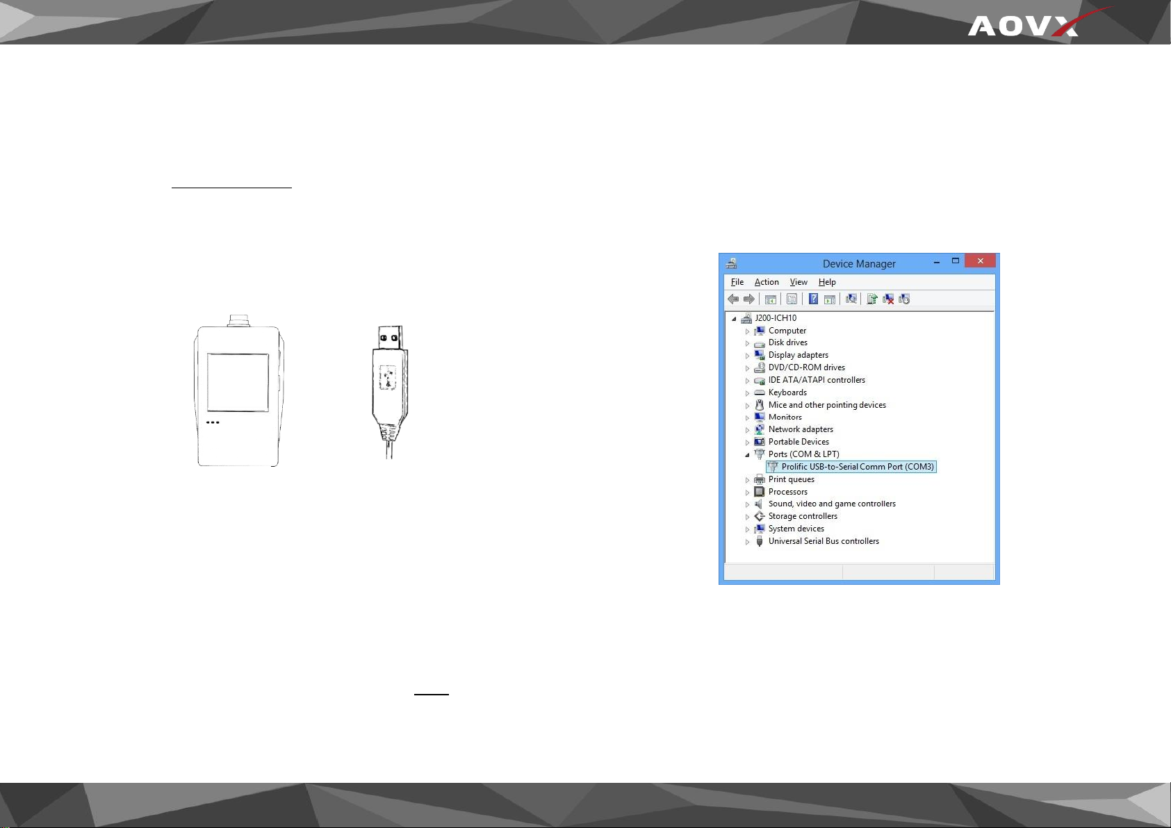
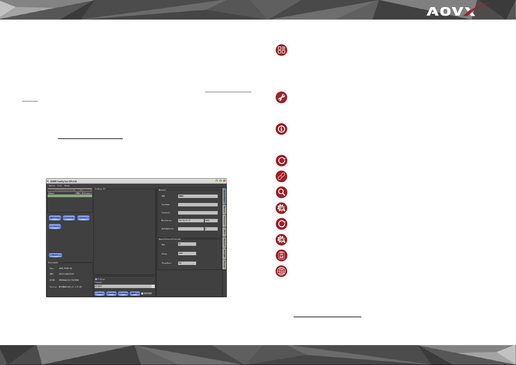
1 Configuration process begins by connected device to computer via
cable.
Open the configuration tool;Select the corresponding COM port;
DeviceInfo is in the lower left corner of the tool, it shows the Type,
IMEI,ICCID and Version of the device.Main buttons offer following
functionality:
①Option- Language- Languages supported by the tool.
-View- Check device log or tool log.
-Property- Settings of the tool.
②Tool- Protocol Analyze- Analyze JT/T808 protocol.
-Download- Loads upgrade package from file..
③About- Version-The version of the tool.
-Help- If you need more information contact us here..
④Refresh-Refresh the COM port and device information.
⑤Connect- Connect the COM port.
⑥Query- Query the device information.
⑦Set- Save configuration to device.
⑧Reset- Restart the device.
⑨Quick start- Configure Network and Report interval.
⑩Device config-configure the device information
⑪Network config-configure band and LTE FDD.
2 Make sure you click set after every configuration.Most important
configurator section is Quick Start – where all your server and network
can be configured.More details about V series configuration can be
found in VX350 User Manual.
Figure_7 Config tool window

www.aovx.com
8
2.5 SMS configuration
Quickly set up your device by sending SMS commands to it:
Table 2 SMS commands
commands
description
IP=<index>,<ip>,<port>
configure IP
APN=<apn>,<name>,<password>
configure APN
TIMEZONE=<zone>
configure timezone
GPIOMODE=<channel>,<mode>
configure GPIO MODE
GPIOVALUE=<channel>,<value>
configure GPIO VALUE
More details about SMS commands can be found in AOVX AT
commands.
Default configuration settings
Report Interval
Run mode:Report every 25 seconds in run mode by default.
Sleep mode:Report every 1800 seconds in sleep mode by
default.
Sleepheart:Report every 180 seconds by default.
Device configuration
Overspeed:Report when the speed over120km/h is overspeed
by default.
Turn angle:Report when turn angle over 25° by default.
Shake level:Report when shake level over 25 by default.
Shake time:It’s in run mode when shake time over 15s by
default.(only for 24V vehicles)
Noshake time:It’s in sleep state when noshake time over 30s by
default.(only for 24V vehicles)
Crash level:Report when crash level over 460 by default.
Timezone:UTC+8 by default.
GNSS Galaxy: GPS+BD by default.

www.aovx.com
9
3 LED light indications
The three indicators are always on under the normal working state of
the device, and all three indicators are off under the sleep state.
System LED indication
Table 3 System LED
COLOR
STATE
MEANING
Red
On
Main power supply or internal
battery power supply
Off
No power or in sleep mode
Network LED indication
Table 4 Network LED
COLOR
STATE
MEANING
Green
On
Linking server succeeded
Off
No power or in sleep mode
Flash
Searching for network or
linking servers
GNSS LED indication
Table 5 GNSS LED
COLOR
STATE
MEANING
Blue
On
GPS positioning succeeded
Off
No power or in sleep mode
Flash
Searching GPS

www.aovx.com
10
Safety Information
This message contains information on how to operate VX350 safely. By
following these requirements and recommendations, you will avoid
dangerous situations. You must read these instructions carefully and
follow them strictly before operating the device!
The allowed voltage range is 9-40V DC.
To avoid mechanical damage, it is advised to transport the device in
an impact-proof package. Before usage, the device should be placed
so that its LED indicators are visible. They show the status of device
operation.
Before installing and unmounting the device from vehicle, ignition
MUST be OFF.
Do not disassemble the device. If the device is damaged,
the power supply cables are not isolated or the isolation
is damaged, DO NOT touch the device before unplugging
the power supply.
All wireless data transferring devices produce interference
that may affect other devices which are placed nearby.
Please consult representatives of your vehicle model
regarding VX350 location on your vehicle. In case you are
not sure about proper connection, please consult
qualified personnel.
The programming must be performed using a PC with
autonomic power supply.
Installation and/or handling during a lightning storm is
prohibited.
The device is susceptible to water and humidity.
AOVX is not responsible for any harm caused by wrong
cables used for connection between PC and VX350
WARNING! Do not use VX350 device if it distracts driver
or causes inconvenience due to VX350 placement. Device
must not interfere with driver.
Battery should not be disposed of with general household
waste. Bring damaged or worn-out batteries to your local
recycling center or dispose them to battery recycle bin
found in stores.
Table of contents
Other AOVX GPS manuals