5. PLACEMENT AND INSTALLATION
5.1 You should site detectors in places with the following conditions:
-minimal vibrations of constructions;
-minimal illumination intensity;
-maximum distance from sources of electrical-magnetic interferences (electric wiring etc.),
infra-red radiation (heat devices);
-elimination of water ingress on the case and penetration out of the base;
-absence of gas, steam, aerosol emission that can cause corrosion.
5.2 Detectors are connected to alarm loop with the help of bases. Bases should be secured
onto the detectors’ site of mounting using two Ø6x25 mm expansion bolts and two Ø3x30 mm
screws. The center-to-center distance between fixing holes of the base is 70±0,2 mm. The view
of the base is shown in Figure 1.
5.3 It is possible to connect to one screw joint of the base up to two 0,2-0,5 mm2 wires.
5.4 The wiring diagram for detectors to control panels is shown in Figure 2.
6. PREPARATION FOR OPERATING AND
SEQUENCE OF OPERATIONS
6.1 Open the package after receiving the detectors, check contents.
ATTENTION! If detectors were in below 0 oC temperature conditions before opening
the package, allow them to acclimatize inside the structure for at least 4 hours.
6.2 Test of detectors for proper operating.
6.2.1 Connect the detector to a 12±1,2 V DC source and ≥50 mA load current. “Plus”
connect to the contact “2”, “minus” – to the contact “3”. Connect a measuring instrument in
resistance measurement mode to contacts “1” and “4”.
6.2.2 Switch on the mains electricity supply and in not less than 10 s introduce a tester
into the test hole on the detector’s cover (a plastic or metal pin Ø1-1,2 mm, 4-5 mm long) and
at the same time switch the stopwatch on.
6.2.3. When the LED is on or relay contacts switch, stop the stopwatch and determine
the response time that should be ≤10s.
6.3 The reset to standby mode is made by turning off the mains electricity supply for at
least 3 s.
7. MAINTENANCE
7.1 Vacuum at least every six months to keep the device working efficiently by firstly
turning off the mains electricity supply and vacuuming through the vents during one minute
using a soft brush attachment or using another compressor of 0,5-3 kg/cm2.
7.2 Then test detectors for proper operating. If the detector is detached from the base
then the test should be made according to p.6.2.
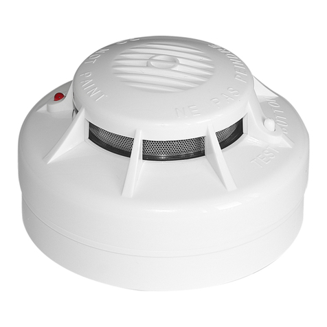
7.3 The test can be made by inserting a tester-pin into the hole on the detector’s cover.
The red LED will be lit when the detector operates properly, and the control panel will issue the
alarm signal.
8. GUARANTEE
1 The detector is warranted by the manufacturer for 18 months upon the date of the
detector’s commissioning but not more than for 30 months from the date of approval by the
manufacturer’s quality control department.
8.2 The manufacturer shall repair or replace detectors within the guarantee term
provided that the rules of installation, timely maintenance, transportation and storage of
detectors have been kept.
8.3 In the case faults according to a reclamation have been removed the guarantee term
is prolonged for the while detectors were not in use because of faults.


