APB-DynaSonics SPECTRA-C User manual

SPECTRA-C / SPECTRA-T
OWNERS MANUAL
APB-DynaSonics, Inc.
20 West End Road
Totowa, New Jersey, 07512, U.S.A.
Tel: 973-785-1101
Fax: 973-785-1105

APB DynaSonics
2 © 2006 APB DynaSonics – All Rights Reserved

3
APB DynaSonics
PS450 Power Supply Inform tion
nd Gener l S fety Instructions
THE SYMBOLS BELOW APPEAR IN THE TEXT THAT FOLLOWS AND HAVE THE FOLLOWING
MEANINGS:
TO AVOID ELECTRIC SHOCK FOLLOW THE INSTR CTION NEXT TO THIS SYMBOL.
TO AVOID AN NSAFE CONDITION FOLLOW THE INSTR CTION NEXT TO THIS SYMBOL
POWER ON-OFF SWITCH
AC INLET CONNECTOR
POWER GOOD INDICATOR
REAR VIEW OF SPECTRA CONSOLE
LOCATION A
LOCATION B
POWER ON-OFF SWITCH
AC INLET CONNECTOR
POWER GOOD INDICATOR
REAR VIEW OF SPECTRA CONSOLE

APB DynaSonics
4 © 2006 APB DynaSonics – All Rights Reserved
IMPORTANT SAFETY INSTR CTIONS
1) Read These Instructions
2) Keep These Instructions
3) Heed All Warnings
4) Follow All Instructions
5) Do Not Use this Apparatus near water
6) WARNING: To reduce the risk of fire or electric shock do not expose this apparatus to rain
or moisture. Do not expose the apparatus to dripping or splashing. Do not place objects
containing liquids, such as vases, on the apparatus.
7) For safety the AC supply must include third wire protective ground connection.
8) Do not block any ventilation openings at the front and rear. Install in accordance with the
manufacturer’s instructions.
9) Do not install near any heat sources such as radiators, heat registers, stoves or other
apparatus (including amplifiers) that produce heat.
10) Do not defeat the safety purpose of the polarized or grounding-type plug. A polarized
plug has two blades with one wider than the other. a grounding type plug has two
blades and a third grounding prong. The wide blade or the third prong are provided for
your safety. If the provided plug does not fit your outlet consult an electrician for
replacement of the obsolete outlet.
11) Protect the power cord from being walked on or pinched particularly at plugs
convenience receptacles and the point where they exit the apparatus.
12) Unplug this apparatus during lightning storms or when unused for long periods of time.
13) Refer all servicing to qualified service personnel. Servicing is required when the
apparatus has been damaged in any way, such as power supply cord or plug is damaged,
liquid has been spilled or objects have fallen into the apparatus, the apparatus has been
exposed to rain or moisture, does not operate normally or has been dropped.

5
INSTALLATION: This power supply is for installation in APB DynaSonics sound mixing consoles and is intended for this
purpose only. Complete consoles are shipped with powers supply(s) installed.
When adding a second power supply to an existing console or replacing an existing power supply follow these
instructions.
1. Switch off AC power. Remove the AC power cord(s). Release the four screws holding the blanking cover plate,
or the existing power supply unit. Remove the cover plate or existing power supply unit. See the diagram for
fastener locations.
2. Insert the additional/replacement power supply unit into the opening and push it firmly to seat the
connections. Replace the four fasteners.
3. Use the power cord supplied to connect a source of AC power between 100V and 240V 50/60Hz.
4. The maximum power requirement for the largest console is approximately 500VA.
5. It is a safety requirement that the AC supply connection includes third wire protective ground connection.
6. Safe operation of the system requires flow of cooling air from the surroundings. Air intake is at the lower
front of the console. Air exhaust is at the upper rear of the console. These openings must not be covered while
the system is on. Air movement is provided by low noise internal fans.
OPERATION
1. Turn on each power supply using the rocker switch on the PS panel.
Normal operation is signaled by illumination of the four green DC voltage indicators at the top rail of the console and by
the illumination of the adjacent blue “PSU GOOD” indicator(s) and also the green “PSU GOOD” indicator on each PS unit
panel(s). The PSU Good condition is reached approx 4 seconds after initial turn-on. This delay gives the Console’s internal
circuits time to stabilize and the PSU Good signal is then used to un-mute the main outputs of the Console.
NOTE: PS450 units will only operate when electrically connected to the console circuits. When removed from the console
chassis and when power is switched on, sensing circuits in the PS unit command a shut-down of the system. In this
condition the PS GOOD indicator on the PS panel will not illuminate and there will be no DC outputs. If this occurs switch
off, replace the unit in the console and wait 30 seconds before switching on.
Normal operation of the PS 450 units requires unrestricted air flow through the unit for cooling purposes. Fans
operate at all times and circulate air within the console chassis. Ambient air reaches the PS via openings at the
front of the console. Ensure that the openings for air intake and exhaust are not obstructed.
AC POWER ON OFF

APB DynaSonics
6 © 2006 APB DynaSonics – All Rights Reserved
OPERATION WITH DUAL POWER SUPPLIES
Single PS450 power units are conservatively rated to operate the 56 channel SPECTRA console continuously. For the
assurance of fully redundant automatic back-up operation the console chassis accepts a second PS450 unit. When a
second PS is present and powered then both power supplies operate and the load is shared. Two independently
protected sources of AC power are recommended for maximum protection against loss of power.
1. Connect each power supply unit to AC power using the cable included.
2. The power supplies must both be switched on using the panel rocker switch on both units.
3. Normal operation is accompanied by the green illumination of the indicators on both units. In addition two blue PS
status indicators are located within view on the console light-bar.
4. If for any reason a supply goes into shut-down then console operation continues using the other unit, the
changeover is automatic and seamless. This event would be signaled by loss of a blue PSU status indicator.
REPLACEMENT OF POWER SUPPLY UNITS
1. Disconnect the AC power cord.
2. Remove four screws that secure the PS unit in the console chassis marked in the diagram with the arrows:
Pull on the power supply handle and the complete unit will slide out of the console chassis.
3. Slide the replacement unit into the console. Replace the four fixing screws.
4. Reconnect the AC power cord.
5. Switch on the power supply using the rocker switch on the panel.
6. Normal operation is signaled by green illumination of the power supply panel indicator(s) and illumination of blue
“PSU GOOD” indicators on the upper console control surface.
7. Note that the power supply units will not operate outside of the console. Automatic circuits prevent operation if the
unit is switched on while out of the console.
SERVICING
CAUTION RISK OF ELECTRIC SHOCK. DO NOT OPEN THE POWER SUPPLY.
There are no user serviceable parts inside the PS unit enclosure. Units contain hazardous AC and DC voltages.
Return defective units to APB-DynaSonics or authorized agent for servicing.
The unit will not operate outside a console. Automatic circuits prevent operation when disconnected from the
console. If this occurs switch off, replace the unit in the console and wait 30 seconds before switching on.

7
APB DYNASONICS POWER SUPPLY PS450
SPECIFICATIONS
High efficiency switch-mode power supply
Steel enclosure with ventilation by internal fans
PS units plug into the APB SPECTRA sound console chassis.
IEC 60320 C13 AC inlet connection
Universal AC input voltage and frequency 100-240V 50/60Hz
Power Factor corrected AC input
Multiple regulated DC outputs: +/- 18V DC @ 10A audio system
+15V DC @ 4.5A fans, lights, control system
+48V DC @ 0.5A input phantom power
Multiple protection systems:
AC input primary fuse, PCB mounted wire ended 20x5mm T8A
AC input in-rush limiting by relay and thermistor
AC input overvoltage MOV clamp
AC input dual series RFI chokes
DC output short circuit protection
DC output overvoltage protection
Automatic safety interlock prevents operation outside the console
Automatic shut-down in the event of elevated & unsafe internal temperature
APPROVALS: USA Recognized power supply with ETL marking and listing
USA and Canada UL60065 7th Edition Electrical Safety
Europe EN60065 7th Edition Electrical Safety
Europe EN55103-1 Emissions (Pending)
PRINCIPAL OF OPERATION
Power is drawn from the AC line and rectified. A switching device maintains the voltage on the internal
DC reservoir capacitor within a controlled range. The main transformer operates at approximately
100kHz and steps down the pr i m a r y p o w e r f r o m a b o u t 4 0 0 V D C t o t h e l o w v o l t a g e s r e q u i r e d f o r t h e f o u r
regulated outputs. The high frequency low voltage AC is rectified to generate the DC output voltages
required. The +/-18V DC s u p p l i e s f o r t h e a u d i o s y s t e m a r e c o u p l e d s o t h a t t he voltage of the negative
supply is a precise mirror of the positive voltage. The 48V DC supply is further processed using a three-
terminal regulator to improve noise and regulation qualities. All DC outputs are short-circuit protected,
the +/-18V supplies are controlled as a pair.
APB DYNASONICS INC 20 WEST END ROAD TOTOWA NJ 07512 USA
Tel: 973.785.1101 Fax: 973.785.1105
www.apb-dynasonics.com
March 2006

APB DynaSonics
8 © 2006 APB DynaSonics – All Rights Reserved
YOUR SPECTRA-C / SPECTRA-T SERIES CONSOLE
Congratulations on your purchase of one of the finest live performance professional audio consoles
manufactured in the United States.
Please take a moment to review this manual. It will insure a better understanding of the operation of this
console and may open up new possibilities into how you use this product.
In addition to the hard copy of this manual, it will appear within our web site www.apb-dynasonics.com with
the latest updates as well as new supplemental information. We suggest that you occasionally check our
web site for additional information about your console as well as for new product releases and news from
APB-DynaSonics.
Should you have any questions or comments about this APB-DynaSonics product, please do not hesitate to
contact us at:
Tel: 973-785-1101
Fax: 973-785-1105
e-mail: [email protected]
M nu l Scope
This manual is not intended to teach you how to mix or how to set up a complete sound system. Should you
be looking for such information, May we suggest that you do a Google Search for “Pro Audio Books” on the
internet, or attend one of the many fine Recording Schools that may be available to you. Many of these
schools offer courses in Live Performance associated subjects as well as basic mixing techniques.
One of the BEST (and our favorite) sources of teaching the technical aspect of system design and operation is
through the Syn-Aud-Con organization:
Synergetic Audio Concepts, Inc.,
8780 Rufing Road
Greenville, IN, 47124 – USA
800-796-2831
Fax : 812-923-3610
For calls outside of the US: 812.923.0174
Email: [email protected]
www.synaudcon.com

9
TABLE OF CONTENTS
INPUTS .................................................................................................................................................... 10
MONO INPUT.......................................................................................................................................10
EQUALIZATION SECTION MONO INPUT (SPECTRA-C)......................................................................11
MONO INPUT EQUALIZATION AND INSERT SECTION (SPECTRA-T) ..................................................12
MONO INPUT - AUXILIARY SEND SECTION .......................................................................................13
MONO INPUT BUS ASSIGNMENT AND PAN ......................................................................................14
MONO INPUT - MUTE, VCA, SOLO AND LEVEL CONTROL .................................................................15
MONO INPUT MODULE REAR PANEL CONNECTORS .......................................................................16
STEREO LINE INPUT SECTION.............................................................................................................17
STEREO LINE INPUT CHANNELS - SPLIT TRACK CONTROL...............................................................18
STEREO LINE INPUT CHANNELS - STEREO EQUALIZATION SECTION ..............................................18
STEREO LINE INPUT CHANNELS - AUX SEND SECTION ....................................................................19
STEREO LINE INPUT CHANNELS - BUS ASSIGNMENT AND BALANCE .............................................20
STEREO LINE INPUT CHANNELS - MUTE, VCA, SOLO AND LEVEL CONTROL....................................21
STEREO LINE INPUT CHANNELS REAR PANEL CONNECTORS..........................................................22
MASTER SECTION.................................................................................................................................. 23
VCA CONTROL SECTION (X8)..............................................................................................................23
AUX MASTER OUTPUT CONTROL (X10).............................................................................................24
AUXILIARY OUTPUT REAR PANEL CONNECTORS .............................................................................25
MATRIX OUTPUT SECTION (X4)..........................................................................................................26
MATRIX OUTPUT REAR PANEL CONNECTORS ..................................................................................27
MASTER OUTPUT SECTION.................................................................................................................28
MASTER OUTPUT REAR PANEL CONNECTORS .................................................................................29
MONO ALTERNATE OUTPUTS (X2).....................................................................................................30
STEREO (RECORD) ALTERNATE OUTPUT ...........................................................................................30
MONITOR / HEADPHONE CONTROL..................................................................................................31
TALKBACK SYSTEM .............................................................................................................................33
SYSTEM METERING .............................................................................................................................34
CONSOLE DIMENSIONS & WEIGHTS.................................................................................................. 35
TECHNICAL SPECIFICATIONS.............................................................................................................. 36

APB DynaSonics
10 © 2006 APB DynaSonics – All Rights Reserved
INPUTS
The following pages describe the input controls and connections of the Spectra-C and Spectra-T consoles.
When a section specifically applies to the C or T versions of the console it is indicated as such in the Heading.
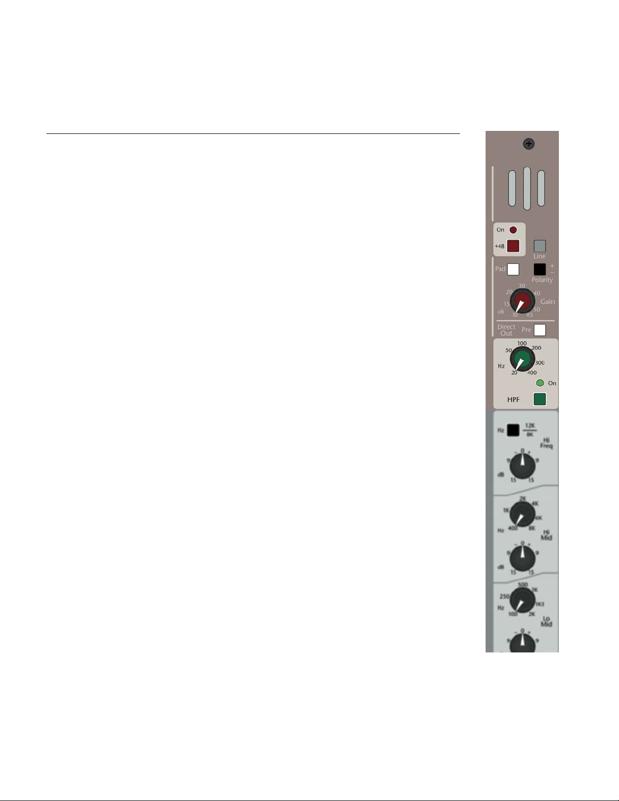
MONO INPUT
Line Switch
Selects between the channel XLR connector (Up) or the TRS Line Jack (Down). On the rear panel, the TRS
jack’s normal contacts are fed from the XLR jack; this allows a line-level signal on an XLR plug to be patched
into the channel without the use of adaptors. If a plug is inserted in both the XLR and 1/4” connector, this
switch selects between the XLR signal and the TRS signal.
+48-Volt Ph ntom Power Switch With LED
When depressed, provides +48-Volt phantom power to the XLR connector. Phantom power is required for
operation of many condenser microphones. See your microphone instructions to see if phantom power is
required or is to be defeated (some –though few- microphones require phantom power NOT be activated or
they may be damaged). A Red LED illuminates when this switch is activated.
P d Switch
When depressed, inserts a 26dB pad into the XLR-input signal path prior to the microphone pre-amplifier to
prevent overload of excessively high input signal levels. Use this pad switch when you find that you are
operating the gain control in the lower third of the control range and still showing excessive signal levels
(yellow and red indications) on the channel meters.
Pol rity Reverse Switch
When depressed, reverses the electrical input polarity of any microphone or line level input signal. Use of
this control may alter the sound quality of an input relative to other channels when multiple microphones
are picking up the same sound. In the past, many consoles labeled this function as “Phase” or used the
symbol “Ø.”
Input G in Control
This control adjusts the amount of gain at the input stage and should be adjusted for the best signal
performance within the console. The goal is to achieve the best signal-to-noise while amplifying input
signals to workable levels, neither too high nor low. The channel’s six-segment meter is used for
visualization of proper (pre-fader) channel levels, while soloing the channel will give more detailed level
information. Proper level is achieved when there is continuous full green illuminated when input sources are
at their highest levels with rare flashes of the yellow and red LED’s.
Direct Output Pre Switch
This switch selects the signal source for the Direct Output from a post-fader to a pre-fader signal source. The
pre-fader source is determined by internal jumpers including: (factory default in bold)
1) Mic Pre Out
2) Insert Send (Post HPF)
3) Pre-Fader (After Insert and EQ)
High-P ss Filter On Switch With LED
When depressed, activates a variable frequency high pass filter (reducing levels of all frequencies below the
set frequency). When this switch is activated, an associated green LED will illuminate.
High-P ss Filter Control
Adjust the high-pass filter corner frequency between 20Hz and 400Hz at a roll off rate of 12dB per octave.
This control is used to remove unwanted signal content below the set frequency such as stage rumble. The
result is usually improved signal quality of the associated input signal while decreasing the low frequency
amplification demand of the audio systems amplifier and speaker combination. This type of filter is also
called a Low-Cut filter.

11
EQUALIZATION SECTION MONO INPUT (SPECTRA-C)
Hi Freq 12kHz/8kHz Selection Switch
This switch selects the corner frequency of the shelving high frequency control. The 8 kHz position will have
a more dramatic effect on high frequency signals than the subtle effect of the 12 kHz frequency position.
Correct frequency selection should be performed by listening for the desired effect on the input signal. If in
doubt, we suggest the use of the 12 kHz position.
Hi Frequency Level Control
Adjust the high frequency cut/boost between +/-15dB. The center “0” position of this control has a detent
to indicate that it is having no effect of the associated channel signal. Boost or cut of the high frequency
level control is usually used for minor tonal adjustments.
Hi-Mid V ri ble Freq Select Control
This control adjusts the center frequency of the hi-mid frequency band EQ between 400Hz and 8kHz at a
bandwidth of approximately one octave.
Hi-Mid Freq Level Control
Adjust the high-mid band cut/boost between +/-15dB. The center “0” position of this control has a detent to
indicate it is having no effect of this frequency band. The high-mid frequency controls are used for minor
tonal adjustment or repair of a specific band of frequencies.
Lo-Mid Freq Control
This control adjusts the center frequency of the low-mid frequency band between 100Hz and 2 kHz at a
bandwidth of approximately one octave.
Lo-Mid Freq Level Control
Adjust the low-mid frequency cut/boost between +/-15dB. The center “0” position of this control has a
detent to indicate it is having no effect of this frequency band. The low-mid frequency controls are used for
minor tonal adjustment or repair of a specific band of frequencies.
Lo Freq Level Control
Adjust the low frequency cut/boost between +/-15dB. The center “0” position of this control has a detent to
indicate that it is having no effect of the associated channel signal. Boost or cut of the low frequency level
control is usually used for minor tonal adjustments.
Lo Freq 120Hz/60Hz Selection Switch
This switch selects the corner frequency of the shelving low frequency control. The 120Hz position will have
a more dramatic effect on low frequency signals than the effect of the 60 Hz frequency position. Correct
frequency selection should be performed by listening for the desired effect on the input signal. If in doubt,
we suggest the use of the 120 Hz position for boost and 60Hz position for cut.
EQ On Switch With LED
This switch places the EQ circuitry into the console signal path. EQ activation is displayed by the illumination
of a blue LED next to the EQ on switch. When not in use, it is suggested that the EQ switch be kept in the OFF
position for the best phase shift performance.

APB DynaSonics
12 © 2006 APB DynaSonics – All Rights Reserved
MONO INPUT EQUALIZATION nd INSERT SECTION (SPECTRA-T)
Insert On Switch With LED
When depressed, this switch places the rear panel TRS insert connector in line with the signal path. The insert
point is after the high pass filter but before the channel EQ and is independent of the EQ-ON switch. Post
high-pass filter signal is always present on this connector’s output. By routing the signal through this
connector, the insert may be used for applications such as having an effect in the signal path that can be
switched in/out.
NOTE: Spectra-C includes the same channel insert connector but it is always On.
V ri ble Hi Freq Select Control
This control adjusts the corner/center frequency of the high frequency band EQ between 800Hz and 16 kHz.
Hi Freq Shelving / Bell Switch
This switch allows selection between a normal shelving response of the high frequency control (tonal
adjustments) and bell shaped curve. When in bell mode, the bandwidth of the band is 2/3 octave for Boost
and 1/4 octave for Cut. This “asymmetrical” setting makes this EQ band highly effective in fixing tonal
problems. When in the shelving position, the boost and cut control will have a more dramatic effect on signals
that in the bell position.
Hi Freq Level Control
Adjust the high frequency cut/boost between +/-15dB. The center “0” position of this control has a detent to
indicate that it is having no effect of the associated channel signal.
V ri ble Hi-Mid Freq Select Control
This control adjusts the center frequency of the hi-mid frequency band EQ between 400Hz and 8 kHz.
Hi-Mid Freq Level Control
Adjust the high-mid frequency cut/boost between +/-15dB. The center “0” position of this control has a detent
to indicate it is having no effect of this frequency band.
Hi-Mid B ndwidth Switch (Norm l-N rrow)
This switch changes the Hi-Mid frequency bandwidth between 1 Octave (Up-normal) and 1/3 Octave (Down-
Narrow) bandwidth. The inclusion of this bandwidth switch enables this frequency band to be used as a tool
in correcting input-specific audio problems in addition to its use as a tonal control.
V ri ble Lo-Mid Freq Select Control
This control adjusts the center frequency of the low-mid frequency band between 100Hz and 2 kHz.
Lo-Mid Freq Level Control
Adjust the low-mid frequency cut/boost between +/-15dB. The center “0” position of this control has a detent
to indicate it is having no effect of this frequency band.
Lo-Mid B ndwidth Switch (Norm l-N rrow)
This switch selects the Low-Mid frequency bandwidth between 1 Octave (Up-normal) and 1/3 Octave (Down-
narrow) bandwidth. The inclusion of this bandwidth switch enables this frequency band to be used as a tool in
correcting input specific audio problems in addition to its use as a tonal control.
V ri ble Lo Freq Select Control
This frequency control adjusts the corner frequency of the low frequency band EQ between 20Hz and 400Hz.
Lo Freq Shelving / Bell Switch
This switch allows selection between a normal shelving response of the lo frequency control (tonal
adjustments) and bell shaped curve. When in bell mode, the bandwidth of the band is 2/3 octave for Boost
and 1/4 octave for Cut. This “asymmetrical” setting makes this EQ band highly effective in fixing tonal
problems. When in the shelving position, the boost and cut control will have a more dramatic effect on signals
that in the bell position.
Low Freq Level Control
Adjust the low frequency cut/boost between +/-15dB. The center “0” position of this control has a detent to
indicate that it is having no effect of the associated channel signal.
EQ On Switch With LED
This switch inserts the EQ into the signal path, which is indicated by the illumination of an LED next to the
switch. When not in use, keep the EQ off for the best phase shift performance.

13
MONO INPUT - AUXILIARY SEND SECTION
Aux 1-4 & 5-10 Pre-Source Switches
These switches select the “Pre” signal source for Aux 1-4 and Aux 5-10 between Pre-fader and Pre-EQ. These
switches are relevant only when the associated (4) Aux Pre-Source (Pre-Src) switches are depressed. The
default Pre-EQ source is internally set to Post-insert. A qualified technician can change this to a Pre-insert or
Pre-high-pass filter setting.
Aux 1-4 Post-F der/Pre-Source
This switch selects the signal source for Auxes 1-4 between Post-fader and Pre-Source (as just determined
above).
Aux Level Controls 1-4
Controls the mix level of the channel into Aux buses 1-4.
Aux 5-6 Post-F der/Pre-Src
This switch selects the signal source for Aux 5-6 between Post-fader and Pre-Source.
Aux 5-6 Stereo Switch
Reconfigures the individual Aux 5 and 6 controls from two level controls to a pan control (5) and a level
control (6). This enables a stereo mix to be generated from within the Aux send section for use with stereo
headphones, effects, or a discrete stereo mix for recording or broadcast use.
Aux 5 Level Control
When in normal mono mode, controls the signal level feeding Aux mix bus 5. When the Aux 5-6 stereo
switch is depressed, this control is now reconfigured into a pan control, which adjusts the balance of signal
being fed to mix buses 5-6.
Aux 6 Level Control
When in normal mono mode, controls the signal level feeding Aux mix bus 6. When the Aux 5-6 stereo
switch is engaged, this control becomes the Aux 5-6 signal level and is fed to the pan control.
Aux 7-8 Post-F der/Pre-Src
This switch selects the signal source for Aux 7-8 between Post-fader and Pre-Source.
Aux 7-8 Stereo Switch
Reconfigures the individual Aux 7 and 8 controls from two level controls to a pan control (7) and a level
control (8). This enables a stereo mix to be generated from within the Aux send section for use with stereo
headphones, effects, or a discrete stereo mix for recording or broadcast use.
Aux 7 Level Control
When in normal mono mode, controls the signal level feeding Aux mix bus 7. When the Aux 7-8 stereo
switch is depressed, this control is now reconfigured into a pan control, which adjusts the balance of signal
being fed to mix buses 7-8.
Aux 8 Level Control
When in normal mono mode, controls the signal level feeding Aux mix bus 8. When the Aux 7-8 stereo
switch is engaged, this control becomes the Aux 7-8 signal level and is fed to the pan control.
Aux 9-10 Post-F der/Pre-Src
This switch determines the signal source for Aux 9-10 between Post-fader and Pre-Source.
Aux 9-10 Stereo Switch
Reconfigures the individual Aux 9 and 10 controls from two level controls to a pan control (9) and a level
control (10). This enables a stereo mix to be generated from within the Aux send section for use with stereo
headphones, effects, or a discrete stereo mix for recording or broadcast use.
Aux 9 Level Control
When in normal mono mode, controls the signal level feeding Aux mix bus 9. When the Aux 9-10 stereo
switch is depressed, this control changes to a pan control adjusting the signal being fed to mix buses 9-10.
Aux 10 Level Control
When in normal mono mode, controls the signal level feeding Aux mix bus 10. When the Aux 9-10 stereo
switch is engaged, this control becomes the Aux 9-10 signal level and is fed to the pan control.
Discrete Sub Woofer Feed
Using Aux Sends
Any Aux bus may be used as a
mixed feed to a subwoofer system
since any of the Aux sends can be
assigned from the master section
to any of the primary outputs
including MONO, the suggested
output for subwoofers. The Left-
Right, Center, and Mono outputs
are controlled from a single VCA
fader maintaining balance
between all outputs.

APB DynaSonics
14 © 2006 APB DynaSonics – All Rights Reserved
MONO INPUT BUS ASSIGNMENT AND PAN
L-R Assignment Switch
Assigns the post-fader channel signal to the Left-Right mix bus through the Left-Right Pan Control. In Stereo
or Dual Mono sound systems, this is the most likely used primary output assignment on the console (In
Stereo operation, signal is panned through the pan pot system to generate a panoramic image – In Dual
Mono operation, an identical signal (pan control positioned to center to send an equal and identical signal
to the left and right mix bus system) is fed providing system redundancy. In systems that include a center
(vocal) cluster, the left and right channels are usually used for stereophonic music reproduction. The
Left/Right outputs are also used for music reproduction when Center and Mono mix buses are used for A-B
vocal mixing. In theatrical applications where identical speakers covering identical physical areas are used
for “A” vocal mix and “B” vocal mix, eliminating any electrical comb filter effect between the two mics.
Center Assignment Switch
Assigns the post-fader channel signal to the Center mix bus. In mono sound systems, this bus can be used as
the primary output (leaving the L-R output available for stereo recording). It is usually used in LCR
installations to feed a discrete signal to the center speaker cluster (when not using the LCR assignment
system). It may also find use as a general purpose post fader output for use as an additional aux or matrix
send or as mix A of an A-B vocal mix.
Mono Assignment Switch
Assigns the post fader input signal to the Mono mix bus. It is used as a general purpose post fader output for
an additional primary console output. It may also be used as mix B of an A-B vocal mix.
LCR Assignment Switch
This switch overrides the Left-Right and Center assignment switches, meaning that the individual L-R and
Center switch positions are no longer active. Instead, the post fader signal is fed directly to the pan control
that is now re-configured to send signal to the Left-Center-Right mix buses in the desired pan location.
P n Control (L-R or LCR)
In normal operation, this control takes the post fader signal from the L-R assignment switch and controls the
proportion of signal feeding between the left and right mix buses. When at the center position, both left
and right signals become equal. The Pan control never has an affect on the feed to the Mono bus, and only
affects the feed to the Center bus when in LCR mode.
When in LCR mode, this control is reconfigured to feed and balance the Left - Center - Right mix buses. As an
example of operation, when this control is set fully counter-clockwise, signal is sent to the left mix bus with
no signal being sent to the center or right mix buses. As the control is turned clockwise, signal starts to
decrease to the left mix bus but begins to increase in the center. No signal is yet being fed to the right mix
bus. When the LCR pan control is positioned to center, no signal is fed to the left or right mix buses, but the
full signal is now fed to the center mix bus. As the knob continues to be turned clockwise, the level begins
to decrease to the center bus and increases to the right mix bus. When the control is turned fully clockwise,
all signal is fed to the right mix bus while no signal is fed to the left or center mix bus. The taper of this
control is tailored to industry standards.
Discrete Sub Woofer Feed
Using Mono Assignment Bus
T
he MONO bus may be used as a
fixed level discrete feed to a sub-
woofer system. The Left-Right,
Center, and Mono outputs are
controlled from a single VCA
master fader maintaining balance
between all outputs including the
MONO sub output when master
si
g
nal levels are chan
g
ed.

15
MONO INPUT - MUTE, VCA, SOLO nd LEVEL CONTROL
Loc l Mute Switch - Intern lly Illumin ted
Activation of this switch will mute the primary outputs as well as all pre and post fader auxiliary sends of the
channel. When depressed, it will illuminate RED, indicating the status of this local mute only; another LED
located beneath this switch indicates the status of any remote activated mutes. Activation of either mute
system will not affect the channel's metering or the Solo-PFL signals, these are both located Pre-Fader/Pre-
Mute. However, the channel's Solo-AFL signal is Post-Fader/Post-Mute (and Post-Assign), so if a channel is
muted (or not assigned), no Solo-AFL will be available.
Remote Mute Activ ted Led
This LED will illuminate red when a mute command is received from any of the possible 12 remote mutes (8
VCA mutes + 4 Mute Groups).
Scene Mute Preset Switches A Thru D
When any of these switches are selected, it will cause the input channel to mute (and Remote Mute LED to
illuminate) when the associated Mute Group switch within the master section is activated. Activation of a
scene mute affects the channel the same way as a Local Mute.
VCA St tus Indic tor (CV= Control Volt ge)
The VCA status LED will illuminate in varying levels of green in proportion to voltage being applied to the
VCA element. This voltage is controlled by the channel fader as well as any of the 8 VCA master faders that
may be assigned to the channel. This LED will turn red if the voltage being applied approaches the
maximum allowable. The CV circuitry will then limit the voltage being applied to the VCA to prevent the
channel fader gain from exceeding the 20dB design limit.
VCA Assignment Switches 1 Through 8
When any of these switches are depressed, it allows the associated master VCA level to have parallel control
of the channel VCA element. Any combination of switches may be chosen, all of which will sum together to
create the final voltage being applied to the VCA element. Maximum voltage being applied to the VCA
element is limited and indicated by the VCA status (CV) LED turning red (see above). These switches also act
as presets for 8 additional scene mutes, but limited to the same assignment groups as the VCA. When any of
the associated VCA mute switches within the master section are activated, the channel will be muted in the
same manner as from the Mute Group section of the console.
Ch nnel Level Meters
6-segment LED meter indicates pre-fader channel level. The top segment peak indicator will illuminate red if
any of the multiple sample points in the signal chain approach 3dB of clipping. A yellow LED illuminates in
the caution zone at +8 reference level. Four green LED segments indicated signal levels of 0, -6, -12, and
Signal Present. The signal present LED first illuminates at approximately -30 and increases in brightness with
level until it is at full intensity. Best operation is achieved when the bottom 3 green LEDs are illuminated with
average input signals with occasional short yellow/red bursts of the +8 and peak LEDs.
100mm VCA Ch nnel F der
This fader adjusts the voltage being applied to the channel’s VCA control electronics. This voltage is mixed
with any of the assigned VCA group voltages to create the final control voltage (CV) for the channel’s VCA
element (as described above). This VCA element controls the Post fader signal level within the channel.
Solo Switch - Intern lly Illumin ted
This switch will illuminate yellow when activated. It will route channel signal to the Master section for display
on the Master solo meters and into the monitor/headphone systems. A switch within the Master section
determines if the signal is sampled pre-fader (PFL) or post fader/post pan pot (AFL). When in pre-fader
mode, it will route the pre-fader mono signal to the Master section. In AFL (post–fader) mode, the channel
post fader/post left-center-right signal is fed to the Master section. The Master section also includes a SOLO
CLEAR switch, which will cancel any Solo switches selected as well as an INPUT PRIORITY switch which will
allow an input channel Solo to temporary cancel an output solo.

APB DynaSonics
16 © 2006 APB DynaSonics – All Rights Reserved
MONO INPUT MODULE REAR PANEL CONNECTORS
1/4” TRS Direct Output Connector
The connector provides a 100 Ω, impedance balanced line level output of the input channel signal. The
front panel Direct Output switch selects the signal between a Post-fader source and a Pre-fader source. The
default signal for the Pre-fader position is AFTER the (1) microphone pre-amplifier but before all other
processing. Additional sources for this output include (2) post high pass filter/insert point, and (3) post EQ.
This utility output can be used to feed a multi-track recording device, effect device, or to feed another
mixing or processing device including distributed monitor mixing systems.
Any changes to the pre fader direct output source options should be made by a qualified technician.
1/4” TRS Insert Connector
This connector allows external processing or effects electronics to be inserted into the channel signal path
after the variable high pass filter. Examples of external devices includes additional equalization, notch filters,
compressors, limiters, vocal doublers, reverb devices, etc. The insert sent has an output impedance of 100
ohms unbalanced and the insert return has an input impedance of 10k ohms unbalanced.
Spectra-T includes an INSERT ON switch with LED to activate the return on this connector (the Insert send
signal is always active) in the Spectra-T mono channels signal path. The insert connector is always active on
Spectra-C consoles. NOTE: The user should ensure that any device inserted into the channel is capable of
maintaining the signal integrity of the console. The device must be able to accept a +22dBu signal without
clipping, and have an output impedance of 100 Ωor less and be capable of driving +22dBu into a 2k Ωload.
1/4” TRS Line Input Connector
This connector accepts line input signals and has an input impedance of >10k ohms. When the front panel
source switch is selected to line input, signal is first sourced from this connector. If nothing is plugged into
this connector, the XLR input is normalled through this connector as a line input signal. The line input may
be balanced or unbalanced signal.
XLR Input Connector
This connector accepts microphone or line input signals, as determined by the front panel input source
switch and if the 1/4” TRS line input connector is occupied. When the front panel input source switch is in
the microphone position, this XLR connector will be used as a microphone input and will have an input
impedance of >3K Ω. When the input selector source switch is in the LINE input position and nothing is
plugged into the 1/4” line input connector, this XLR connector is used as a balanced line input with an input
impedance of >10k Ω. If a connector is plugged into the 1/4” line input connector, the XLR connector will
always be configured as a microphone input connector with an input impedance of >3 kΩ. This is a locking
connector. To remove an XLR cable, depress the Tab on the console connector before attempting to remove
the cable plug from the console connector.

17
STEREO LINE INPUT SECTION
TRS/RCA Line Input Switch
Selects the stereo input source between the rear-panel 1⁄4” TRS jacks ( 20k Ωbalanced @ +4dBu) and the
RCA connectors (10kΩunbalanced @ -10dBV).
Left Input Pol rity Reverse Switch
This switch reverses the electrical input polarity of the left input signal. Use of this switch may alter the
sound quality of an input signal relative to other channels.
Left Input G in Control
This control is used to adjust the input gain of the left line input for optimum electrical performance without
producing audible noise (hiss) at high gain settings. The channel LED meters and the solo meters are used in
assisting in setting the control for correct gain. Separate left and right input gain controls are provided to
allow for better signal optimization when operated in split track mode.
Right Input Pol rity Reverse Switch
This switch reverses the electrical input polarity of the right input signal. Use of this switch may alter the
sound quality of an input signal relative to other channels.
Right Input G in Control
This control is used to adjust the input gain of the right line input signal for optimum electrical performance
without producing audible noise (hiss) at high gain settings. The channel LED meters and the solo meters
are used in assisting in setting the control for correct gain levels. Separate left and right input gain controls
are provided to allow for better signal optimization when operated in split track mode.

APB DynaSonics
18 © 2006 APB DynaSonics – All Rights Reserved
STEREO LINE INPUT CHANNEL - SPLIT TRACK CONTROL
Split Tr ck Mode On Switch With LED
This switch converts the channel from conventional Stereo input operation to a dual mono “Split Track”
channel. This function is most useful when dealing with the Voices-Left/Music-Right sources commonly used
in House of Worship performances. The two Split-Track controls allow the operator to independently control
the blend of the L&R channel signals feeding both the Auxes and the Main buses.
Aux Send Split Tr ck Control
When the “Split Track” mode switch is pressed, the Aux Send split track control will be active. When this
control is set fully counter-clockwise, the pre-fader source for the auxiliary sends is the left line input-only.
When this control is set fully clockwise, the pre-fader source for the auxiliary sends is the right line input-
only. When set to its center position, there is an equal amount of left and right input signal being sent in
summed-mono to the auxiliary send controls. From the center position, turning the control clockwise will
increase the amount of right input while decreasing the left input signal being sent to the auxiliary controls.
Turning the control counter-clockwise will increase the amount of left input while decreasing the right input
signal being sent to the auxiliary controls.
Ch n Send Split Tr ck Control
When the “Split Track” mode switch is pressed, the Chan split track control will be active; this effectively
turns the stereo signal within the module into a mono signal. The Blend control allows the operator to adjust
the mixture of the L&R signals making up that mono mix. When this control is set fully counter-clockwise,
the pre-fader source for the mix assignment is the left line input. When this control is set fully clockwise, the
pre-fader source for the mix assignment is the right line input. When set to its center position, there is an
equal amount of left and right input signal being sent in summed-mono to the mix assignment controls.
From the center position, turning the control clockwise will increase the amount of right input while
decreasing the left input signal being sent to the mix controls. Turning the control counter-clockwise will
increase the amount of left input while decreasing the right input signal being sent to the mix controls.
LINE INPUT CHANNEL - STEREO EQUALIZATION SECTION
Left-Right High P ss Filter Switch
The switch (at the top of the section, above the split track control) activates an 80Hz @-18dB per octave high
pass filter on both the left and right input signal paths of the stereo input channel.
Left-Right High Frequency Level Control
Adjusts the high frequency shelving cut/boost between +/-15dB. The center “0” position of this control has
a detent to indicate that it is having no effect. Boost or cut of the high frequency level control is usually used
for minor tonal adjustments. Use of this EQ control will affect both the left and right signal paths.
Left-Right High-Mid Frequency Level Control
Adjusts the high-mid frequency bell-shaped cut/boost between +/-15dB. The center “0” position of this
control has a detent to indicate it is having no effect. Use of this EQ control will affect both the left and right
signal paths.
Left-Right Low-Mid Frequency Level Control
Adjusts the high-mid frequency bell-shaped cut/boost between +/-15dB. The center “0” position of this
control has a detent to indicate it is having no effect. Use of this EQ control will affect both the left and right
signal paths.
Left-Right Low Frequency Level Control
Adjusts the low frequency shelving cut/boost between +/-15dB at the corner frequency selected. The center
“0” position of this control has a detent to indicate that it is having no effect. Use of this EQ control will affect
both the left and right signal path.
Low Frequency 120Hz/60Hz Selection Switch
This switch selects the corner frequency of the shelving low frequency control. The 120Hz position will have
a more dramatic effect on low frequency signals than the 60 Hz position. Correct frequency selection should
be performed by listening for the desired effect on the input signal.
EQ On Switch With LED
This switch inserts the Left and Right EQ circuitry into the signal path. Stereo EQ activation is displayed by
the illumination of an LED next to the EQ ON switch. When not in use, it is suggested that the EQ switch be
kept in the OFF position for best phase shift performance.

19
STEREO LINE INPUT CHANNELS - AUX SEND SECTION
Ch nnel Pre-F der/Pre-EQ Switch (Pre-Source Select)
This switch selects the Pre signal source for Aux 1-10 between Pre-Fader or Pre-EQ. This switch is relevant
only when an associated (4) Aux Pre-Source switch is selected.
Aux Level Control 1-4
Controls the mix level of the input channel into Aux mix buses 1-4. These Aux feeds are always a summed-
mono blend of th L & R channel signals. Source for this signal is determined by the Aux 1-4 Post-Fader/Pre-
Source switch.
Aux 1-4 Pre/Post F der Switch
This switch selects the signal source for Aux 1-4 between Post-fader or Pre-Source
Aux 5 Level Control
The Aux 5 level control adjusts the amount of the Left channel signal feeding Aux mix bus 5. When the Aux
5-6 L+R switch is selected, this aux signal becomes a mono blend of the left and right channel signals.
Aux 6 Level Control
The Aux 6 level control adjusts the amount of the Right channel signal feeding Aux mix bus 6. When the Aux
5-6 L+R switch is selected, this aux signal becomes a mono blend of the left and right channel signals.
Aux 5-6 L+R Switch
This switch reconfigures the feed to the auxiliary controls between the Aux 5-Left / Aux 6-Right stereo
signals into a mono blend of the left and right signals to both controls.
Aux 5-6 Post –F der/Pre-Source Switch
This switch determines the signal source for Aux 5-6 between Post fader and the earlier defined Pre-Source.
Aux 7-8 nd Aux 9-10 Controls
The controls for Aux p irs 7-8 nd 9-10 oper te in the s me m nner s the controls of Aux 5-6.

APB DynaSonics
20 © 2006 APB DynaSonics – All Rights Reserved
STEREO LINE INPUT CHANNELS - BUS ASSIGNMENT AND BALANCE
B l nce (P n) Control (To Left-Right)
In both stereo and split-track mono operation, this control feeds the post fader signal to the L-R assignment
switch (dual-mono or stereo) and controls the proportion of signal feeding the left and right mix buses.
When at the center position, both left and right output signals are equal. When the SUM switch is depressed,
this control acts then as a PAN control positioning the now summed mono signal within the stereo pan
image.
Sum Mono Switch (Du l Mono Effects Return Mode)
Depressing this switch sums the Left and Right signal into mono for special applications. With the use of this
switch, the channel may be used as a dual-mono Effects Return channel. This is possible because of the
separate input gain controls and polarity reverse switches on the inputs, allowing the adjustment of the gain
or balance between two independent line inputs (effect devices).
Mono Assignment Switch
Assigns the mono (L&R equally mixed) post fader input signal to the Mono mix bus. It is used as a general
purpose post fader output for use as an additional primary console output, Aux or matrix send including use
for surround or sub-woofer mixes.
L-R Assignment Switch
When in normal Stereo mode, assigns the post fader stereo signal to the Left-Right mix buses through the
Balance Control. When in Split Track mode, this switch feeds the output of the split track mix control to the
balance control.
Center Assignment Switch
Assigns the mono (L&R equally mixed) post fader input signal to the CENTER (additional mono) mix bus.
When this channel is being used for music playback, the usual assignment locations will be the Left-Right
mix buses with assignment to the Center channel not usually used. Assignment to the Center (Mono) mix
bus is provided for situations where the center bus is being used to feed a discrete mix to another location
or it is being used for the primary output of the console to drive a Mono sound system.
NOTE:
If the Split Track button is depressed, the L&R channel signals have already been combined/mixed by the use
of the Blend control. So, for all switches involving the L&R channel signals (L-R, Mono, Center, SUM), this fact
should be taken into account. If the Blend control is set for full Left or full Right, the L&R combination that
these switches call for will be modified by that earlier Blend setting. If no L or no R is present because of a
full-Blend, then that missing L or R signal will NOT be combined by these later assignment switches.
Discrete Sub Woofer Feed From The Mono Assignment Bus
The MONO bus may be used as a fixed level discrete feed to a sub-woofer system. The Left-Right,
Center, and Mono main outputs are controlled from a single VCA master fader maintaining balance
between all outputs including the MONO sub output when master signal levels are changed.
This manual suits for next models
1
Table of contents
Other APB-DynaSonics Recording Equipment manuals