OPERATION / MAINTENANCE MANUAL
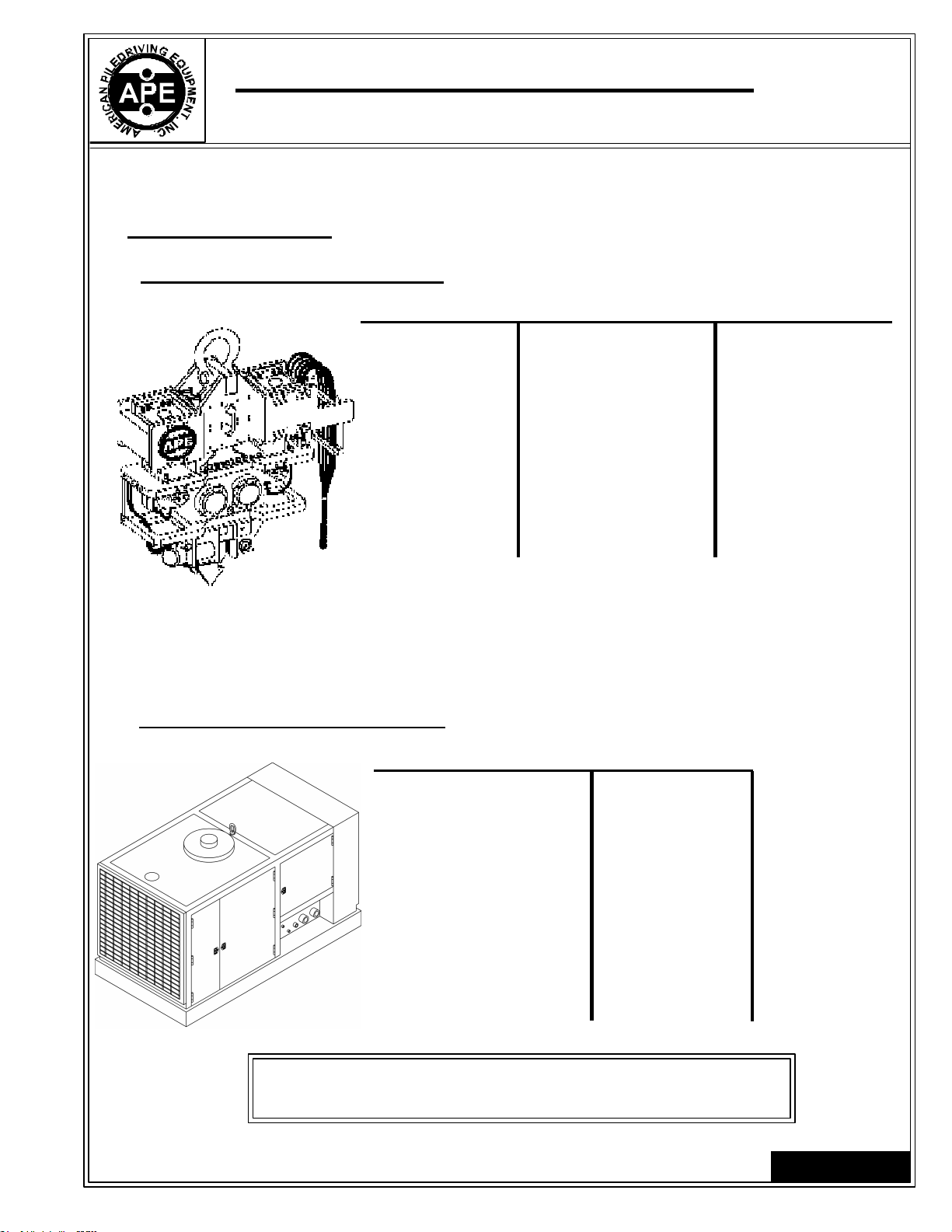
MODEL 150/150T VIBRATORY DRIVER WITH MODEL 350 POWER UNIT
7032 SOUTH 196th - KENT, WA. 98032 - (253) 872-0141 / FAX (253) 872-8710
Table of Contents
Revision Record ............................................................................................ i
Preface .......................................................................................................... ii
Table of Contents .......................................................................................... iii
Safety Precautions ........................................................................................ v
Warranty........................................................................................................ vii
I. GENERAL INFORMATION ........................................................................................ 1-1
I-1. Machine Features ....................................................................................... 1-1
I-2. Machine Specifications ............................................................................... 1-2
A. Model 150/150T Vibro ...................................................................... 1-2
B. Model 350 Power Unit ..................................................................... 1-2
I-3. General Description of 150/150T Vibro .......................................................... 1-3
A. Suppressor Housing ......................................................................... 1-4
B. Vibrator Gearbox ............................................................................. 1-5
C. Clamp Attachment ........................................................................... 1-6
D. Optional Attachments ...................................................................... 1-7
I-4. General Description of Model 350 Power Unit ................................................ 1-8
II. MAJOR COMPONENT DEFINITION.......................................................................... 2-1
II-1. Vibro Identification ..................................................................................... 2-1
II-2. Hose Identification ..................................................................................... 2-4
II-3. 150 Sheet Clamp Identification ........................................................................ 2-5
II-4. Model 350 Power Unit Skid Identification ...................................................... 2-7
II-5. Quick Disconnect Couplings ........................................................................ 2-8
II-6. 100 Caisson Clamp Identification ................................................................. 2-9
II-8. Tool Set Identification ..................................................................................... 2-11
II-9. Control Panel Identification ........................................................................... 2-12
II-10.Control Panel Schematic ........................................................................... 2-13
II-11.Pendant ................................................................................................... 2-14
III. LOADING AND UNLOADING .................................................................................. 3-1
III-1. Model 150/150T Vibratory Driver ................................................................. 3-1
III-2. Model 350 Power Unit ............................................................................... 3-1
III-3. What to do if damaged during shipment ...................................................... 3-1
IV. PREPARATION AND OPERATION .......................................................................... 4-1
IV-1. Rigging of Vibratory Driver ......................................................................... 4-1
IV-2. Installing the Clamp Attachment ................................................................ 4-1
IV-3. Plumbing the Vibro Hoses to the Power Unit ............................................... 4-2
IV-4. Filling Vibrator Pressure Hose ................................................................... 4-3
IV-5. Bleeding Clamp Attachment Hydraulic Hoses ............................................. 4-3
IV-6. Precautions and Rules for Operation .......................................................... 4-4
IV-7. Relief Valve Settings Prior to Operation - Model 350..................................... 4-5
IV-8. Shut-down Procedures .............................................................................. 4-7
IV-9. Operation of the Control Pendant ............................................................... 4-8
IV-10.Normal Steps to Operate Vibrator ............................................................. 4-8
V. MAINTENANCE....................................................................................................... 5-1
V-1. Daily Maintenance Required Prior to Operation ............................................ 5-1
V-2. Checklist After Power Unit Engine Has Started ............................................ 5-1
V-3. Maintenance and Adjustments: ...... (75 Hours) ............................................... 5-2
V-4. Maintenance and Adjustments: ...... (Eccentric Bearings)........................... 5-2
V-5. Maintenance and Adjustments in Severe Conditions ..................................... 5-2
V-6. Lubrication ............................................................................................... 5-2
A. Vibratory Gearbox ............................................................................ 5-2
B. Clamp Attachment ........................................................................... 5-2
Page iii
II-7. Caisson Clamp Cylinder Asm Identification ................................................... 2-10
Copyright © 1994 American Piledriving Equipment, Inc. All Rights Reserved