EK80
EK80U Rev A 5
BEFORE YOU GET STARTED
• All Apex Microtechnology amplifiers should be handled using proper ESD precautions.
• Always use the heat sink included in this kit.
• Always use adequate power supply bypassing.
• Do not change the connections while the circuit is powered.
• Initially set all power supplies to the minimum operations levels allowed in the device data sheet.
• Check for oscillations.
• Please refer to Application Note, AN01 for general operating conditions.
ASSEMBLY INSTRUCTIONS
During the assembly, please refer to the circuit schematics, assembly drawings, and the data sheet of the
part being used on the evaluation kit.
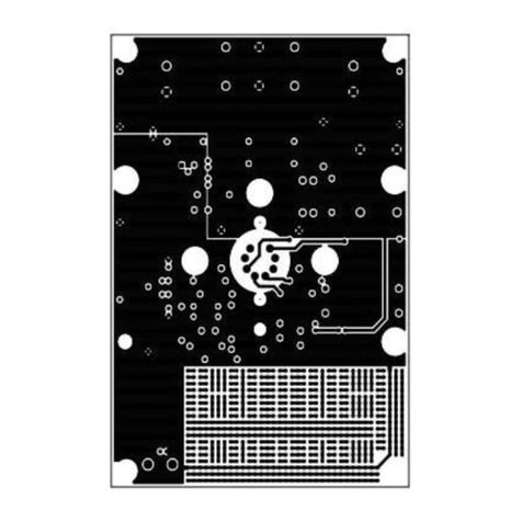
1. Note that each side of the circuit board is identified as either the TOP SIDE or the BOTTOM SIDE. The
component side has the designators printed on that side. Unless otherwise specified, install components
on the TOP SIDE. The majority of components are installed on the TOP SIDE.
2. A pin receptacle is supplied with this evaluation kit. Break it into strips 20 and 22 pins long. Two strip seg-
ments can be installed end on end if necessary. Insert the carrier strip through the BOTTOM SIDE and sol-
der the cage jacks on the TOP SIDE. Once the cage jacks are soldered, remove the carrier strip, leaving
only cage jacks soldered on the board.
3. Install SMT components first. C1-C8 are all surface mount X7R capacitors used for power supply bypass-
ing, particularly for higher frequencies.
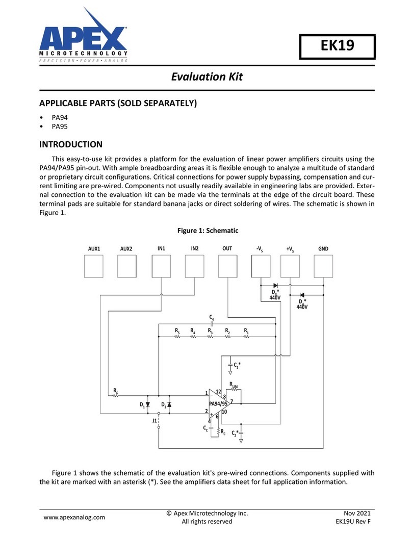
4. The next components to solder are all through hole diodes and resistors in the desired circuit configura-
tion, for the exception of the larger TO-220 package resistors, RISO1 and RISO2.
5. After the smaller through hole circuit components have been installed, this is a good opportunity to
install the test points, TP1-TP14.
6. The next components to solder on are the banana jack connectors, P1-P7.
7. Install the BNC connectors, P9 and P10.
8. Install the six-pin terminal block connector P8.
9. Install the large electrolytic capacitors, C9 and C10. Be sure to verify the proper polarity when installing.
10. Using the provided hardware, attach HS2 and HS3 to RISO1 and RISO2. These assemblies will be installed
next on to the board by soldering the resistor leads. Ensure that the resistor leads do not short against
the heatsinks. Adding thermal grease between the resistors if available can improve the power dissipa-
tion of these components.
11. Install the standoffs on the corners of the PCB. The screws go in through the TOP SIDE and should allow
the EK to hold the heatsink above the workstation surface.
12. On the BOTTOM SIDE, install the 4 grommets which will support the heatsink on the PCB.
13. Install a CD64 onto HS1 using the provided hardware. Adding thermal grease between the resistors if
available can improve the power dissipation of these components.
14. Plug in the CD64 and heatsink assembly into the BOTTOM SIDE of the PCB. Be sure to check the orienta-
tion of the part while installing since the part has asymmetrical pins. Use the provided hardware to screw
in the heatsink into the grommets.
