API 600 User manual

292930
Miller Manufacturing, Glencoe, MN 55336 USA • www.miller-mfg.com
Read Instructions Thoroughly Before Use
PRECAUTIONS
• Use with grounded outlets only. Many older homes do not have
properly grounded outdoor electrical outlets. Check with an electrician
if you have any doubts concerning your electrical ground.
• When using an extension cord, only use one rated for “outdoor use”.
The cord must be rated as an“outdoor” cord by the manufacturer and
must be rated to carry more than 150 watts of power.
• Do not let the connection lay in the snow or water.
•
Always be sure the bath is placed safely away from possible snow drifts.
• Do not place bath directly on the ground.
• Never place the bath where puddling or pooling of water is likely
to occur.
• To clean the bath scrub out the dish without immersing lower section
in water. Never fully immerse bath in water.
• Rate of evaporation: this bath was designed to be attractive to the
birds both in shape, slope, texture and depth. Due to these features the
bath has a rather large surface area relative to the amount of water it
holds. This is typical of a well designed, functional bird bath. During the
dry winter months the above features, coupled with a 45 to 55 degree
water temperature, will naturally accelerate evaporation. Therefore, do
not be alarmed if you must add water on a daily basis.
GENERAL INFORMATION
The Heated Bird Bath does not heat the water all the time, as it contains
an automatic thermostat that cycles the water temperature between 40° F
and 50° F. This bird bath is designed to clamp to deck railings or pedestals
or it may also be placed on any flat surface. Once the mount is in place, you
can simply spin the bath on and off the mount for routine cleaning. You do
not have to reapply the mount every time you wish to clean your bird bath.
After the winter season, you can remove your mount from your pedestal or
deck railing and replace your Heated Bird Bath with your regular bird bath.
By doing this, you will extend the life of your Heated Bird Bath.
If your pedestal has a protrusion or“nub” on top: The bird bath will not
clamp to a pedestal which has a screw protruding from the top (unless the
screw is removable). If your pedestal has some other protrusion on top, try
connecting the bracket to the protrusion following the same directions
as listed under the section titled Bird Bath pedestal 7.25” or less (follow the
directions as if the protrusion is the diameter of your pedestal).
Mounting your Heated Bird Bath
First, decide on what surface you will be mounting the bath. Second,
measure the width of the surface – if a deck rail, or measure the diameter –
if the surface will be a pedestal or stand. Third, look under the appropriate
heading in this manual and follow the directions.
Your bracket is attached to the bottom of the bird bath. To remove, simply
spin the bracket counterclockwise. Also contained is a bag of loose parts.
You will note the bracket, found under the bath, is preassembled to fit a
pedestal 7.25”or less. However, if your pedestal falls within this range, you
must still adjust the bracket to fit your particular pedestal diameter.
If you are planning to use a mount under one of the other headings, you
will want to disassemble this mount and use the parts to construct your
chosen mount.
The manual starts off with drawings of all the parts included with the
bracket. For assembly you will need a small screwdriver and an adjustable
wrench.
292930
HEATED 20” BIRD BATH
150 Watts, 120 Volts
Item # 600
PARTS
A.
F.
K.
B.
G. L.
C.
H.
M.
D. I. N.
E. J.
Extending Arm (3) 3/8”(short)
Set Screw (3)
1
1
/
2
”(short)
Set Screw (3)
1.5”Elevator Bolt (1)
2”Elevator
Bolt (1)
5/8”Machine Screw (3)
Angle Bracket (1)
Washer (5)
Hex Regular Nut (3)
3”Carriage Bolt (2)
Shim (3)
1”Elevator Bolt (1)
Hex Nut 1cm (thin nut) (1)
Round
Disc (1)

292930
HEATED 20” BIRD BATH
Item # 600
Miller Manufacturing, Glencoe, MN 55336 USA • www.miller-mfg.com
Mounting to your pedestal
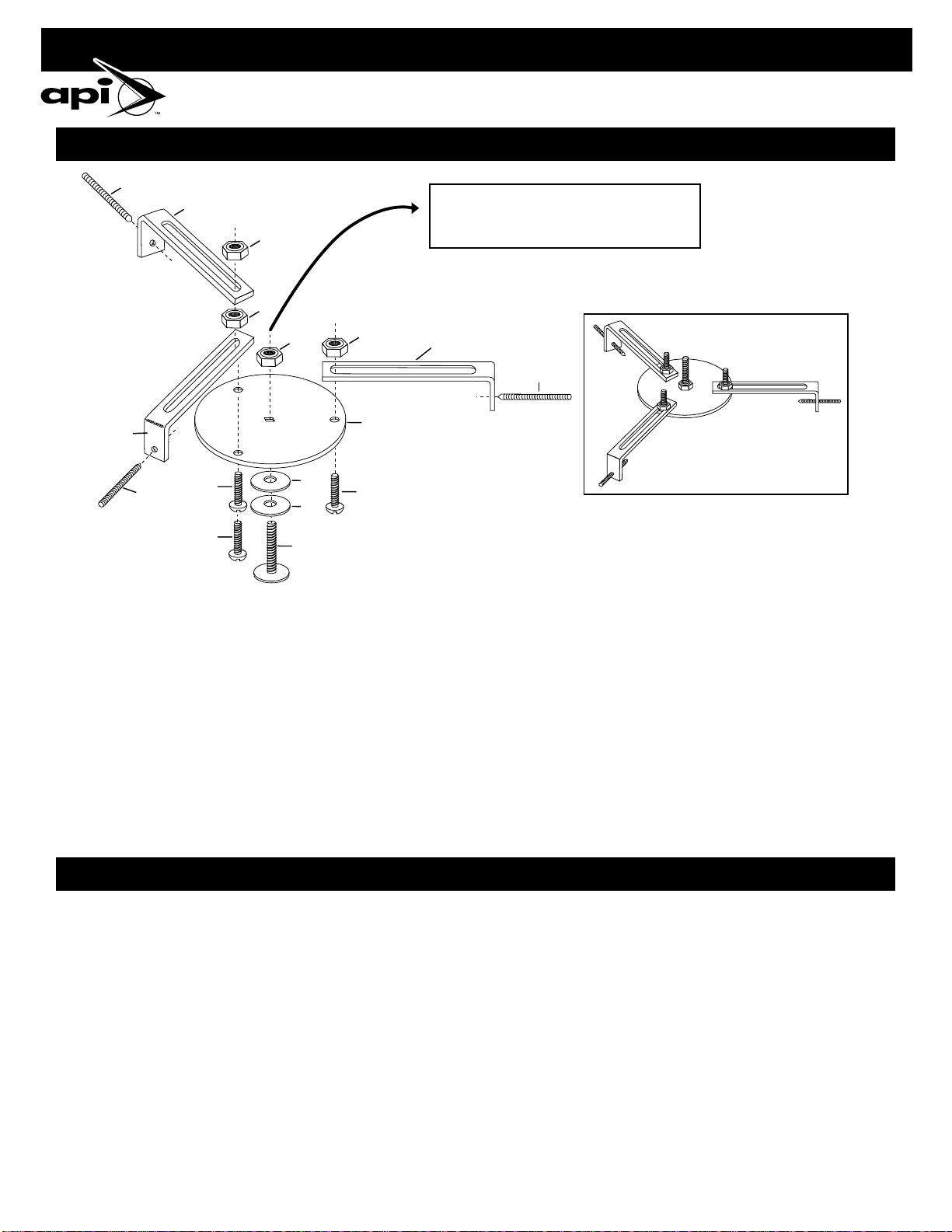
1. Assemble bracket following the exploded diagrams above.
2. Back the three set screws (part #F) out as far as possible.
3. Place the mount on the center of the pedestal and center the mount so
the center bolt (part #D) is directly in the center of the pedestal.
4. Loosen the center nut (Note: you do not have to take the mount off
your pedestal to loosen or tighten this nut (part #E), located on top of
the round disc, and open or close the arms so that the mount conforms
to the sides of your pedestal.)
5. Position the arms as tight as possible against the sides of your pedestal.
6. Make sure the center bolt is still positioned in the center of your
pedestal. (If the center bolt is misaligned with the center of your
pedestal – reposition the mount and repeat step #4 again).
7. Tighten the center nut. You must use a wrench and fasten this nut as
Mounting to a metal pole
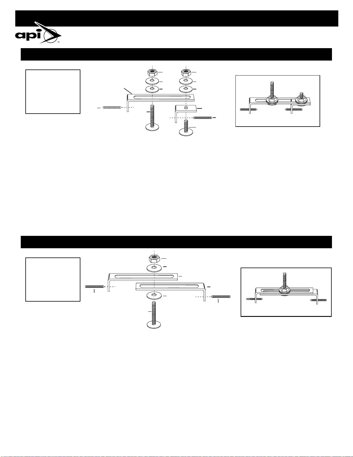
1. Follow the exploded diagram for a pedestal 7.25”or less.”Substitute
long set screws (part #G) for short set screws (part #F). Screw each long
set screw (part #G) into each arm (part #A) approximately 1.25”.
2. Do not attach shims (part #B).
3. Place the mount on the center of the pole and center the mount so the
center bolt (part #D) is directly in the center of the pole.
4. Each of the three arms (part #A) should be extended an equal distance
from side of the pole (i.e. the 1.25”distance allowed for each set screw).
If not, loosen the center nut (Note: you do not have to take the mount
off your pole to loosen or tighten this nut (part #E), and open or close
the arms so that the cone points of the long set screws (part #G) rest
against the sides of the pole.
tight as possible. (Note: you do not have to remove the mount from
your pedestal to loosen or tighten this nut).
8. Check to be sure the mount is aligned straight. If the mount is slightly
crooked, move the corresponding arm upward in order to compensate.
9. Use a screwdriver to tighten the three set screws (part #F). Do not over
tighten these screws because this will bend the arms of the mount.
Just tighten each one enough to dig slightly into the surface (if your
pedestal is plastic, the set screws will probably not dig into the surface
which will be sufficient).
10. Place the bath on the center screw and rotate the bath clockwise until tight.
11. If your bath sits crooked, you may remove the bath by rotating counter-
clockwise. Then loosen the proper set screw and adjust the mount by
moving the corresponding arm upward, re-tighten the set screw before
placing your bath back on the mount.
5. Tighten the center nut. You must use a wrench and fasten this nut as
tight as possible. (Note: you do not have to remove the mount from
your pedestal to loosen or tighten this nut).
6. Press on the top of your mount as you tighten the set screws (part #G).
Do not let the mount rise off the pole as you tighten the set screws. The
lowest arm (part #A) should always remain level and flush against
the top of the pole surface. Do not over-tighten the set screws!
7. Place the bath on the center screw and rotate the bath clockwise
until tight.
8. If your bath sits crooked, then you have probably over-tightened the
three set screws. Remove the bath, loosen the three set screws (part #G)
and repeat step 6.
MOUNTING TO A FEEDER POLE OR OTHER METAL POLE
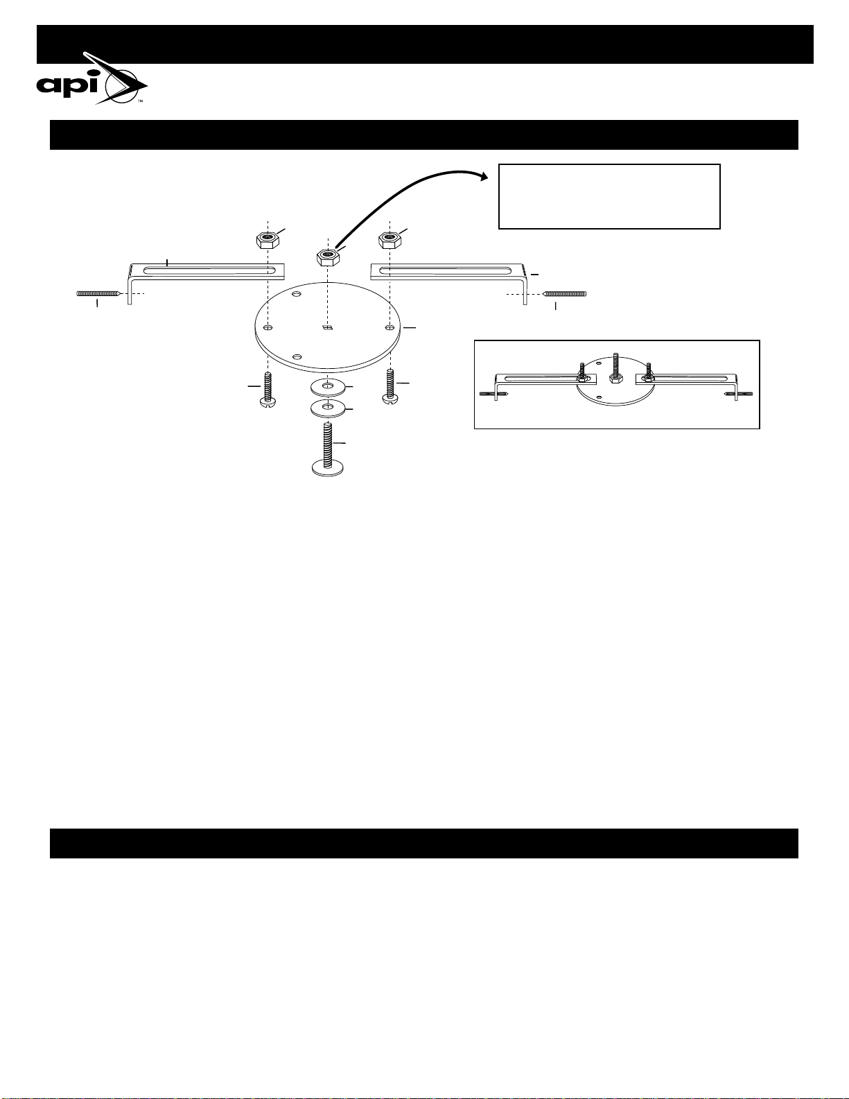
IF MOUNTING TO A PLASTIC PEDESTAL OR IF THE DIAMETER OF YOUR BIRD BATH IS 7.25” OR LESS
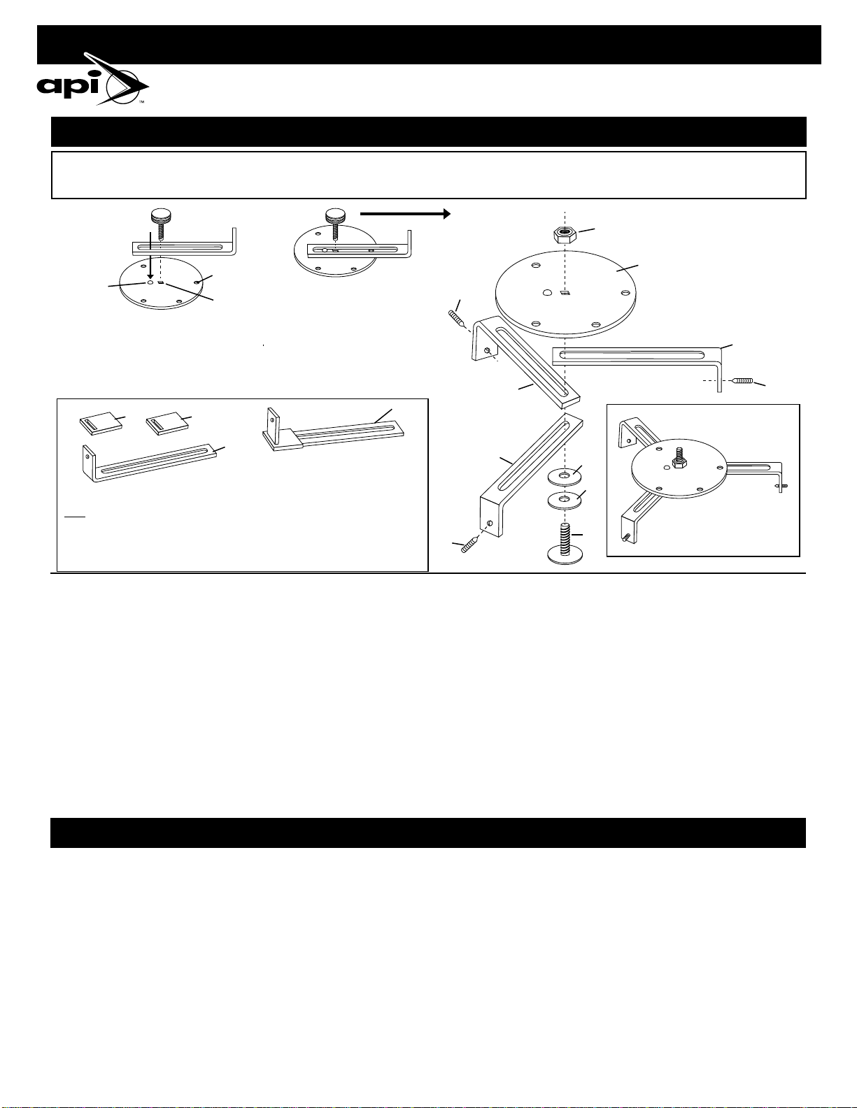
1. Place the first arm (part #A) so the dimple in the round disc (part #C) is inside the slot in
the arm (part #A). 2. The slot in the arm (part #A) should be in a straight line with the dimple,
the square hole and the round hole on the edge of the disc. 3. Make sure the dimple is at
the opposite end from the right angle bend in the arm (part #A). 4. Proceed with placing the
other two arms (part #A) in place followed by the washers (part #K) and elevator bolt (part #D)
as shown in the diagram labeled Assembly #2.
Attachment of Shims
Only if your bird bath pedestal is hollow or has a hole in the center, attach the three
shims (part #B) as shown. These enable the mount to rest level. Two shims should be
placed on the first arm (part #A) which rests against the round disc (part #C). One shim
should be placed on the middle or second arm which is “sandwiched” between the first
and third arm. No shims should be attached to the third arm.
The bracket has been preassembled in this position and is attached to the bottom of the bird bath. To remove, simply spin the bracket counterclockwise. You will still have to assemble
the shims – if necessary (see diagram on shim attachment). Loosen the nut (part #E) to allows adjustment of the arms (part #A) to the diameter of your pedestal. Then follow directions
#3 through #10 under “Mounting to your Pedestal”.
(Assemble 1)
Dimple
Round
Hole
Square
Hole
(Assemble 2)
(Exploded Diagram)
(Exploded Diagram)
(Exploded Diagram)
(Finished Diagram)
(Finished Diagram)
(Finished Diagram)
A
A
BB
E
F
F
F
C
D
K
K
A
A
A

292930
HEATED 20” BIRD BATH
Item # 600
Miller Manufacturing, Glencoe, MN 55336 USA • www.miller-mfg.com
Mounting to your pedestal
1. Assemble bracket following exploded diagram.
2. Screw the set screws (part #G) at least 1”into the mount.
3. Place the mount on the center of the pedestal and center the mount so
the center bolt (part #N) is directly in the center of the pedestal.
4. Loosen the three screws (part # I) holding the arms (part #A) in place.
Then open or close the arms so that the mount conforms to the sides
of your pedestal (i.e. so the points of the set screws (part #G) are against
the sides of your pedestal).
5. Make sure the center bolt (part #N) is still positioned in the center of
your pedestal. (If the center bolt is misaligned with the center of your
pedestal – reposition the mount and repeat step #3 again).
6. T
ighten the three arms as tight as possible. You must use a wrench and
screwdriver on the three screws (part #I) holding the arms in place.
Mounting to your pedestal
1. Assemble bracket following exploded diagram found in section for
bird bath pedestal between 7.25”and 8.25”except substitute small set
screws (part #F) in place of large set screws (part #G).
2. Back the three set screws (part #F) out of arms (part #A) as far as
possible.
3. Place the mount on the center of the pedestal and center the mount so
the center bolt (part #N) is directly in the center of the pedestal.
4. Loosen the three screws (part #I) holding the arms (part #A) in place.
Then open or close the arms so that the mount conforms to the sides of
your pedestal (i.e. so the arms are “hugging”the sides of your pedestal
and are as close as they can possibly go).
5. Make sure the center bolt (part #N) is still positioned in the center of
your pedestal. If the center bolt is misaligned with the center of your
pedestal – reposition the mount and repeat step #3 again.
7. Check to be sure the arms (part #A) are all at the same level.
8. Use a screwdriver to tighten the three set screws (part #G). Do not over
tighten these screws because this will bend the arms of the mount.
Just tighten each one enough to dig slightly into the surface (if your
pedestal is plastic, the set screws will probably not dig into the surface
but will bend the surface which will be sufficient).
9. Place the bath on the center screw and rotate the bath clockwise until
tight against the arms of the mount.
10. If your bath sits crooked, you may remove the bath by rotating
counterclockwise. Then loosen the proper set screw (part #G) and
adjust the mount by moving the corresponding arm upward. Re-
tighten the set screw before placing your bath back on the mount.
6.
Tighten the three arms as tight as possible. You must use a wrench and
screwdriver on the three screws (part #I) holding the arms in place.
7. Check to be sure the arms (part #A) are all at the same level.
8. Use a screwdriver to tighten the three set screws (part #F). Do not over
tighten these screws because this will bend the arms of the mount.
Just tighten each one enough to dig
slightly
into the surface (if your
pedestal is plastic, the set screws will probably not dig into the surface
but will bend the surface which will be sufficient).
9. Place the bath on the center screw and rotate the bath clockwise until
tight against the arms of the mount.
10. If your bath sits crooked, you may remove the bath by rotating
counterclockwise. Then loosen the proper set screw (part #F) and adjust
the mount by moving the corresponding arm upward. Re-tighten the
set screw before placing your bath back on the mount.
IF THE DIAMETER OF THE TOP OF YOUR BIRD BATH PEDESTAL IS BETWEEN 7.25” AND 8.25”
IF THE DIAMETER OF THE TOP OF YOUR BIRD BATH PEDESTAL IS BETWEEN 8.25” AND 12”
If this nut does not fit flush and tight with the round disc
(part #C), then you should add 2 washers between the
round disc and the nut.
(Exploded Diagram)
L
L
L
E
I
I
I
G
G
G
C
K
K
N
A
A
A
(Finished Diagram)

292930
HEATED 20” BIRD BATH
Item # 600
Miller Manufacturing, Glencoe, MN 55336 USA • www.miller-mfg.com
Mounting to wooden post
1. Assemble mount, with exception of part #J, and leave the center nut
(part #E) loose enough so that you can move the 3 arms (part #A) to fit
the post.
2. Place the mount on the center of the pedestal and center the mount so
the center bolt (part #D) is directly in the center of the pedestal.
3. Make sure the arm (part #A) with the short set screw (part #F) is flush
against the side of the post with the set screw (part #F) backed out as
far as possible. The other two arms (part #A) with the longer set screws
(part #G) should be pushed together as far as possible. There will be a
gap between these two arms and the side of the post.
1. Assemble mount to metal rail as shown in exploded diagram. Sandwich
rail between arms (part #A).
2. When attaching mount make sure the carriage bolts (part #M) are
“hugging”the sides of the metal rail. They must be as close against the
rail as possible.
3. Use a wrench to tighten the nuts on the carriage bolts (part #M). Do not
over-tighten because excessive tightening will cause the arms (part #A)
to bend. A slight bend is okay.
4. Make sure the center bolt is still positioned in the center of your
pedestal. If the center bolt is misaligned with the center of your
pedestal – reposition the mount and repeat step #3 again.
5. Using a wrench, tighten the center nut (part #E) as tight as possible.
6. Use a screwdriver to tighten the three set screws. While tightening
these make sure that the mount remains level. Do not over-tighten the
set screws because this will cause the mount to bend. Tighten the set
screws only enough to slightly dig into the wood.
7. After your mount is fastened tightly, add angle bracket (part #J) to the
end of the arm (part #A) containing the small set screw (part #F). Attach
part #J so there is not an air gap between the wooden post and part #J
(to eliminate an air gap you must back the small set screw out of part #J
to the end of the arm (part #A).
8. Tighten the set screw (part #F) in the angle bracket (part #J).
9. Place the bath on the center screw and rotate the bath clockwise until
tight against the round disc (part #C).
10. If your bath sits crooked, you may remove the bath by rotating
counterclockwise. Then loosen the proper set screw (part #F or part #G)
and adjust the mount by moving the corresponding arm upward. Re-
tighten the set screw before placing your bath back on the mount.
4. Do not be concerned if you can still “twist” the mount back and forth.
This“twisting”will be eliminated once the bath is“spun” onto the mount.
5. Set the bath onto the center screw (part #H) and “spin” the bath into
place. It should be spun until the bottom surface of the bath rests tight
against the surface of the railing and there is no wobble.
4” X 4” WOODEN POST OR “LOOKER” MFG. STAND
MOUNTING TO A METAL DECK RAILING
(Finished Diagram)
(Finished Diagram)
(Assembly of Part J)
(Exploded Diagram)
L
F
J
I
G
A
F
K
K
D
A
A
C
G
E
(Exploded Diagram)
(Finished Diagram)
M
M
L
L
A
K
K
HE
A

292930
HEATED 20” BIRD BATH
Item # 600
Miller Manufacturing, Glencoe, MN 55336 USA • www.miller-mfg.com
1. Assemble mount as shown but leave the nuts (part #L) loose enough to
allow adjustment of bracket.
2. Back out the long set screw (part #G) as far as possible out of the arm
(part #A) and out of the angle bracket (part #J).
3. Position bracket so the elevator bolt (part #H) is in the center of rail.
4. Open or close bracket by sliding angle bracket (part #J) along arm (part
#A) so that the arm (part #A) and angle bracket (part #J) are hugging
the sides of the railing.
a. If the bracket will not open large enough for the width of your railing
try the next size bracket configuration.
b.If the bracket will not close small enough for your rail, screw the set
screw (part #G) deeper into both the arm (part #A) and the angle
bracket (part #J). This will act as a spacer.
1. Assemble mount as shown but leave the nuts (part #L) loose enough to
allow adjustment of bracket.
2. Back out the long set screw (part #G) as far as possible out of both arms
(part #A).
3. Position bracket so the elevator bolt (part #H) is in the center of rail.
4. Open or close bracket by sliding angle bracket (part #A) towards each
other. Ideally so that both arms (part #A) are hugging the sides of the
railing.
a. If the bracket will not open large enough for the width of your railing
try the next size bracket configuration.
b.If the bracket will not close small enough for your rail, push the arms
together until they stop. Position the center elevator bolt (part #H) in
the center of your wooden rail. Then screw the set screws (part #G)
deeper into both the arms until the cone points on the set screws
(part #G) hit the wooden surface. This will act as a spacer.
5.
Make sure that the center bolt is in the center of the rail. Then tighten both
nuts (part #L). You must use a wrench to insure that both nuts are tight.
6. While applying pressure to the top of the mount (so the bottom surface
of the elevator bolt (part #H) is flush against the wooden surface) use a
screwdriver to tighten the two set screws (part #G). Do not over-tighten
because this will cause the mount to bend. As a rule, tighten the set
screw just past the point of the mount bending.
7. Do not be concerned if the mount assembly wobbles back and forth.
This wobble will correct itself once the bath is “spun”onto the mount
and tightened against the wooden surface.
8. Set the bath onto the center screw (part #H) and “spin” the bath into
place. It should be spun until the bottom surface of the bath rests tight
against the surface of the railing and there is no wobble.
5. Make sure that the center bolt (part #H) is in the center of the wooden
rail. Then tighten the center nut (part #L). You must use a wrench to
insure this nut is tight.
6. While applying pressure to the top of the mount (so the bottom surface
of the elevator bolt (part #H) is flush against the wooden surface) use
a screwdriver to tighten the two set screws (part #G). The set screws
should dig into the wood – but only slightly. Do not over-tighten
because this will cause the mount to bend. As a rule, tighten the set
screws just past the point of the mount bending.
7. Do not be concerned if the mount assembly wobbles back and forth.
This wobble will correct itself once the bath is “spun”onto the mount
and tightened against the wooden surface.
8. Set the bath onto the center screw (part #H) and “spin” the bath into
place. It should be spun until the bottom surface of the bath rests tight
against the surface of the railing and there is no wobble.
MOUNTING TO A METAL DECK RAILING
MOUNTING TO A WOODEN RAILING UP TO 3.5” WIDE
MOUNTING TO A WOODEN RAILING FROM 3.5” TO 8.75” WIDE
If this nut (part #L) does
not fit tight against the
washer (part #K), then
you will have to add ad-
ditional washers. Do this
until the nut fits tight.
If this nut (part #L) does
not fit tight against the
washer (part #K), then
you will have to add ad-
ditional washers. Do this
until the nut fits tight.
J
D
G
(Exploded Diagram)
L
K
H
A
G
K
L
K
K
(Finished Diagram)
(Finished Diagram)
(Exploded Diagram)
L
K
H
A
A
G
K
G

292930
HEATED 20” BIRD BATH
Item # 600
Miller Manufacturing, Glencoe, MN 55336 USA • www.miller-mfg.com
1. Assemble mount as shown but leave the nuts (part #I) loose enough to
allow adjustment of bracket.
2. Back out the long set screws (part #G) as far as possible out of both
arms (part #A).
3. Position bracket so the elevator bolt (part #N) is in the center of your
rail.
4. Open or close bracket by sliding both arms (part #A) towards each
other. Ideally so that both arms (part #A) are hugging the sides of the
railing.
a. If the bracket will not close small enough for your rail, push the arms
together until they stop. Position the center elevator bolt (part #N) in
the center of your wooden rail. Then screw the set screws (part #G)
deeper into both arms until the cone points on the set screws (part
#G) hit the wooden surface. This will act as a spacer.
b.If the bracket is still too large then try the next smaller configuration
for a wooden railing.
c. If the bracket is too small then try a permanent mount. See the
section titled “permanent mount”.
1. Take the elevator bolt (part #H) and insert this bolt through the center
square hole in the round disc (part #C). Fasten this elevator bolt
(part #H) with 3 washers (part #K) and 1 nut (part #L). Make sure the
washers are on the same side of the round disc (part #C) as the nut
(part #L). Use a wrench to tighten this assembly.
5. Make sure that the center bolt (part #N) is in the center of your wooden
rail. Then lift the mount off the surface and tighten the two screws (part
#I). You must use a wrench and screwdriver to tighten these properly.
6. While applying pressure to the top of the mount (so the bottom surface
of the elevator bolt (part #N) is flush against the wooden surface) use
a screwdriver to tighten the two set screws (part #G). The set screws
should dig into the wood – but only slightly. Do not over tighten
because this will cause the mount to bend. As a rule, tighten the set
screws just past the point of the mount bending.
7. Do not be concerned if the mount assembly wobbles back and forth.
This wobble will correct itself once the bath is “spun”onto the mount
and tightened against the bracket surface.
8. Set the bath onto the center screw (part #N) and “spin” the bath into
place. It should be spun until the bottom surface of the bath rests tight
against the surface of the mount and there is no wobble. If the mount
comes loose, tighten the set screws (part #G). Keep doing this until
the bath rests tight against the mount and the mount is fastened tight
against the wood surface.
2. You may fasten this assembly to any flat surface via any two of the holes
provided along the diameter of the round disc.
3. Set the bath onto the center screw (part #H) and “spin” the bath into
place. It should be spun until the bottom surface of the bath rests tight
against the mounting surface and there is no wobble.
MOUNTING TO A WOODEN RAILING 8.75” TO 12” WIDE
PERMANENT MOUNT
If this nut does not fit flush and tight with the
round disc (part #C), then you should add 2
washers between the round disc and the nut.
(Exploded Diagram)
(Finished Diagram)
A
A
K
K
N
I
C
G
G
L
L
L
I
Table of contents
Popular Bathtub manuals by other brands

Agua
Agua BRIZE-66 quick start guide

Kohler
Kohler K-1969 Homeowner's guide

DURAVIT
DURAVIT Blue Moon 710143 Mounting instruction

Kohler
Kohler Windward K-1115-LA Roughing-In Guide

American Standard
American Standard System I Operating and maintenance instruction manual

glass 1989
glass 1989 petra 180/75 manual